EP0364746A1 - Drehteller als Sitzfläche für Behinderte - Google Patents
Drehteller als Sitzfläche für Behinderte Download PDFInfo
- Publication number
- EP0364746A1 EP0364746A1 EP89117342A EP89117342A EP0364746A1 EP 0364746 A1 EP0364746 A1 EP 0364746A1 EP 89117342 A EP89117342 A EP 89117342A EP 89117342 A EP89117342 A EP 89117342A EP 0364746 A1 EP0364746 A1 EP 0364746A1
- Authority
- EP
- European Patent Office
- Prior art keywords
- cover plate
- retaining ring
- turntable according
- base plate
- plate
- Prior art date
- Legal status (The legal status is an assumption and is not a legal conclusion. Google has not performed a legal analysis and makes no representation as to the accuracy of the status listed.)
- Granted
Links
- 239000011324 bead Substances 0.000 claims description 6
- 230000002093 peripheral effect Effects 0.000 claims 2
- 230000000295 complement effect Effects 0.000 claims 1
- 125000006413 ring segment Chemical group 0.000 description 8
- 230000015572 biosynthetic process Effects 0.000 description 1
- 230000003670 easy-to-clean Effects 0.000 description 1
- 230000037431 insertion Effects 0.000 description 1
- 238000003780 insertion Methods 0.000 description 1
- 230000000284 resting effect Effects 0.000 description 1
Images

Classifications
-
- A—HUMAN NECESSITIES
- A61—MEDICAL OR VETERINARY SCIENCE; HYGIENE
- A61G—TRANSPORT, PERSONAL CONVEYANCES, OR ACCOMMODATION SPECIALLY ADAPTED FOR PATIENTS OR DISABLED PERSONS; OPERATING TABLES OR CHAIRS; CHAIRS FOR DENTISTRY; FUNERAL DEVICES
- A61G7/00—Beds specially adapted for nursing; Devices for lifting patients or disabled persons
- A61G7/10—Devices for lifting patients or disabled persons, e.g. special adaptations of hoists thereto
- A61G7/1073—Parts, details or accessories
- A61G7/1076—Means for rotating around a vertical axis
Definitions
- the invention relates to a turntable according to the features of the preamble of claim 1.
- Such a turntable is known as a standing surface for the disabled from US 2,757,388.
- a ball ring is provided for easy rotation.
- Disabled people have to be turned 90 ° in a sitting position in bed, on a chair and often on a lifting device placed in a bathtub to bring their legs into a new position.
- the known turntable is not suitable for this purpose, since a pad is missing, which must also be easy to clean and replace and which nevertheless has to be fastened so that it cannot move.
- the turntable must be as low as possible and the upholstery must be soft enough to prevent the formation of pressure points when sitting or lying down. On the other hand, it must be sufficiently rigid and rotatable even when it is pressed into a soft bed mattress.
- the object of the invention is to provide a turntable which takes account of the aforementioned requirements, and which in particular comprises a non-displaceable cushion pad which is easily removable and replaceable and which can be easily completely dismantled without assembly tools in order to To be able to clean individual parts.
- a positive engagement of the support mat is achieved by sharp-edged bends of the clamped edge and / or by means of insertion pins.
- the omission of a ball bearing enables the turntable to be disassembled easily and provides sufficient frictional resistance to prevent unwanted rotary movements in response to the body movements of the disabled person.
- a turntable 10 consists of a base plate 12, a cover plate 14, a flexible support mat 16 resting thereon and a retaining ring 18 which engages over the support mat 16 and clamps onto the cover plate 14. All four parts are made of plastic and are arranged axially symmetrical to the central axis 20.
- the base plate 12 has a plate-shaped outer edge 22 with raised edge bead 24 and a thick-walled central central part 26 with a flat top surface. In the middle part there is a coaxial, circular depression 28 which tapers in cross-section towards its upper opening. Slightly protruding suction cups are pressed into holes in the base plate.
- the cover plate 14 has a plate-shaped central part 30, which rests directly on the central part 26 of the base plate 12, a lower-lying, plate-shaped flat outer edge 32 which forms a flat running gap with the outer edge 22 of the base plate 12, and a conical connecting wall 34 protrude four molded-on circular arc-shaped and circumferentially spaced locking tabs 36, each having an outer edge bead 38 on the bottom.
- the edge beads 38 have an outside diameter which is slightly larger than the diameter of the opening of the recess 28, so that the latching tabs 36 elastically bend inwards when the cover plate 14 is pressed axially against the base plate 12 and snap out again after passing through the opening and thus the cover plate 14 lock the base plate 12 in the axial direction.
- the locking tabs 36 center the cover plate 14.
- the retaining ring 18 is composed of eight identical ring segments 19 which abut one another in axial planes on the end face.
- the top surface of the retaining ring 18 is convexly curved and adjoins that of the edge bead 24 without a shoulder.
- the retaining ring 18 has an outer edge 40 which is surrounded by the edge bead 24 of the base plate 12 with play like a frame and which engages around the outer edge 32 of the cover plate and lies flush with it on the base side.
- Adjoining the outer edge 40 is a stepped flat support surface 42 which rests on the outer edge 32. From the support surface 42 of each ring segment 19 four locking pins 44 project downwards, which are releasably locked in holes 46 in the outer edge 32 of the cover plate 14.
- a first flat clamping surface 48, a conical clamping surface 50 and a second flat clamping surface 52 adjoin the support surface 42 radially inwards. These three clamping surfaces 48, 50, 52 form, with the adjacent top surface of the top plate 14, an annular gap 54 which is doubly angled in cross section, the constant gap width of which is somewhat less than the thickness is the support mat 16, the compressed edge of which is clamped in a form-fitting manner in the annular gap 54.
Landscapes
- Health & Medical Sciences (AREA)
- Nursing (AREA)
- Life Sciences & Earth Sciences (AREA)
- Animal Behavior & Ethology (AREA)
- General Health & Medical Sciences (AREA)
- Public Health (AREA)
- Veterinary Medicine (AREA)
- Invalid Beds And Related Equipment (AREA)
- Seats For Vehicles (AREA)
- Tables And Desks Characterized By Structural Shape (AREA)
- Switches With Compound Operations (AREA)
- Automatic Disk Changers (AREA)
- Keying Circuit Devices (AREA)
- Crystals, And After-Treatments Of Crystals (AREA)
- Chairs Characterized By Structure (AREA)
- Accommodation For Nursing Or Treatment Tables (AREA)
- Control Of Combustion (AREA)
- Push-Button Switches (AREA)
- Bathtub Accessories (AREA)
- Brushes (AREA)
- Forklifts And Lifting Vehicles (AREA)
- Passenger Equipment (AREA)
- Mattresses And Other Support Structures For Chairs And Beds (AREA)
- Non-Flushing Toilets (AREA)
- Chairs For Special Purposes, Such As Reclining Chairs (AREA)
- Orthopedics, Nursing, And Contraception (AREA)
- Holders For Apparel And Elements Relating To Apparel (AREA)
Abstract
Description
- Die Erfindung betrifft einen Drehteller gemäß den Merkmalen des Oberbegriffes von Patentanspruch 1.
- Ein solcher Drehteller ist als Stehfläche für Behinderte aus der US.2 757 388 bekannt. Zur leichten Drehbarkeit ist ein Kugelkranz vorgesehen. Behinderte müssen in sitzender Stellung im Bett, auf einem Stuhl und häufig auf einem, in einer Badewanne angeordneten Liftgerät um 90° gedreht werden, um die Beine in eine neue Position zu bringen. Für diesen Zweck ist der bekannte Drehteller nicht geeignet, da eine Polsterauflage fehlt, die auch leicht zu reinigen und auszutauschen sein muß und gleichwohl verschiebesicher befestigt sein muß. Der Drehteller muß eine möglichst geringe Bauhöhe haben und die Polsterung muß weich genug sein, um die Bildung von Druckstellen beim Sitzen oder Liegen zu verhindern. Andererseits muß er biegesteif genug und auch noch dann drehbar sein,wenn er in eine weiche Bettmatratze eingedrückt ist.
- Aufgabe der Erfindung ist es, einen Drehteller zu schaffen, der den vorgenannten Erfordernissen Rechnung trägt, und der insbesondere eine verschiebesichere Polsterauflage umfaßt, die leicht abnehmbar und austauschbar ist und der ohne Montagewerkzeuge leicht vollständig demontierbar ist, um die Einzelteile reinigen zu können.
- Diese Aufgabe wird durch die Kennzeichnungsmerkmale von Patentanspruch 1 gelöst.
- Außer der kraftschlüssigen Einklemmung des Randes der Auflagematte ist gemäß Ausgestaltungen der Erfindung vorgesehen, daß durch scharfkantige Abbiegungen des eingeklemmten Randes und/ oder durch Einsteckdorne ein Formschluß der Auflagematte erzielt wird.
- Die Weglassung eines Kugellagers ermöglicht erst die unkomplizierte Demontage des Drehtellers und vermittelt einen ausreichenden Reibungswiderstand, um unerwünschte Drehbewegungen als Reaktion auf Körperbewegungen des Behinderten zu vermeiden.
- Anhand eines Ausführungsbeispieles sei die Erfindung näher beschrieben.
- Es zeigt
- FIG. 1 eine Draufsicht auf den neuen Drehteller, bei dem ein Ringsegment entfernt ist,
- FIG. 2 eine Seitenansicht des Drehtellers nach FIG. 1,
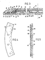
- FIG. 3 eine vergrößterte Schnittansicht des Drehtellers,
- FIG. 4 eine Draufsicht auf das in FIG. 1 fehlende Ringsegment in größerem Maßstab und
- FIG. 5 eine Seitenansicht des Ringsegementes gemäß FIG. 4.
- Ein Drehteller 10 besteht aus einer Bodenplatte 12, einer Deckplatte 14, einer auf dieser aufliegenden flexiblen Auflagematte 16 und einem Haltering 18, der die Auflagematte 16 übergreift und an der Deckplatte 14 festklemmt. Alle vier Teile bestehen aus Kunststoff und sind achssymmetrisch zur zentralen Achse 20 angeordnet.
- Die Bodenplatte 12 hat einen plattenförmigen Außenrand 22 mit erhöhtem Randwulst 24 und ein dickwandiges zentrales Mittelteil 26 mit ebener Deckfläche. Im Mittelteil befindet sich eine koaxiale, kreisförmige Vertiefung 28, die sich zu ihrer oberen Öffnung hin querschnittsmäßig verjüngt. In Löcher der Bodenplatte sind geringfügig vorstehende Saugnäpfe eingedrückt. Die Deckplatte 14 hat ein plattenförmiges Mittelteil 30, das auf dem Mittelteil 26 der Bodenplatte 12 unmittelbar aufliegt, einen tiefer liegenden, plattenförmigen ebenen Außenrand 32 der mit dem Außenrand 22 der Bodenplatte 12 einen ebenen Laufspalt bildet, und eine konische Verbindungswand 34. Vom Mittelteil 30 ragen vier angeformte kreisbogenförmige und umfangsmäßig distanzierte Rastlappen 36 nach unten, die bodenseitig je einen äußeren Randwulst 38 aufweisen. Die Randwülste 38 haben einen Außen durchmesser der etwas größer als der Durchmesser der Öffnung der Vertiefung 28 ist, sodaß sich die Rastlappen 36 elastisch nach innen biegen, wenn die Deckplatte 14 axial gegen die Bodenplatte 12 gedrückt wird und nach Passieren der Öffnung wieder nach außen schnappen und damit die Deckplatte 14 an der Bodenplatte 12 in axialer Richtung verrasten. Die Rastlappen 36 zentrieren die Deckplatte 14.
- Der Haltering 18 setzt sich aus acht identischen Ringsegmenten 19 zusammen, die stirnseitig in Axialebenen aneinanderstoßen. Die Deckfläche des Halteringes 18 ist konvex gewölbt und schließt absatzfrei an diejenige des Randwulstes 24 an. Der Haltering 18 hat einen Außenrand 40, der vom Randwulst 24 der Bodenplatte 12 mit Spiel rahmenartig umfaßt ist und der den Außenrand 32 der Deckplatte umgreift und bodenseitig bündig damit liegt. An den Außenrand 40 schließt sich eine abgesetzte ebene Stützfläche 42 an, die auf dem Außenrand 32 aufliegt. Von der Stützfläche 42 jedes Ringsegmentes 19 ragen vier Rastzapfen 44 nach unten, die in Löchern 46 des Außenrandes 32 der Deckplatte 14 lösbar verrastet sind. Mit einer Stufe schließen sich radial einwärts an die Stützfläche 42 eine erste ebene Klemmfläche 48, eine konische Klemmfläche 50 und eine zweite ebene Klemmfläche 52 an. Diese drei Klemmflächen 48, 50,52 bilden mit der benachbarten Deckfläche der Deckplatte 14 einen im Querschnitt doppelt abgewinkelten Ringspalt 54, dessen konstante Spaltbreite etwas geringer als die Dicke der Auflagematte 16 ist, deren zusammengedrückter Rand in den Ringspalt 54 formschlüssig eingeklemmt ist. Von der konischen Klemmfläche 50 ragen zwei Reihen angeformter Dorne 56 etwa parallel zur Drehachse 20 des Drehtellers 10 nach unten bis nahe an die konische Verbindungswand 34 heran und graben sich beim Aufsetzen des Ringsegmentes 19 in die Auflagematte 16 ein, die gleichzeitig radial nach außen gespannt wird.
Claims (10)
Priority Applications (1)
| Application Number | Priority Date | Filing Date | Title |
|---|---|---|---|
| AT89117342T ATE75391T1 (de) | 1988-10-19 | 1989-09-20 | Drehteller als sitzflaeche fuer behinderte. |
Applications Claiming Priority (2)
| Application Number | Priority Date | Filing Date | Title |
|---|---|---|---|
| DE3835532A DE3835532C1 (de) | 1988-10-19 | 1988-10-19 | |
| DE3835532 | 1988-10-19 |
Publications (2)
| Publication Number | Publication Date |
|---|---|
| EP0364746A1 true EP0364746A1 (de) | 1990-04-25 |
| EP0364746B1 EP0364746B1 (de) | 1992-04-29 |
Family
ID=6365416
Family Applications (1)
| Application Number | Title | Priority Date | Filing Date |
|---|---|---|---|
| EP89117342A Expired - Lifetime EP0364746B1 (de) | 1988-10-19 | 1989-09-20 | Drehteller als Sitzfläche für Behinderte |
Country Status (15)
| Country | Link |
|---|---|
| US (1) | US5000513A (de) |
| EP (1) | EP0364746B1 (de) |
| JP (1) | JPH0795970B2 (de) |
| CN (1) | CN1013019B (de) |
| AT (1) | ATE75391T1 (de) |
| AU (1) | AU616806B2 (de) |
| CA (1) | CA1316090C (de) |
| DE (2) | DE3835532C1 (de) |
| DK (1) | DK167597B1 (de) |
| ES (1) | ES2030570T3 (de) |
| FI (1) | FI91597C (de) |
| GR (1) | GR3004828T3 (de) |
| IE (1) | IE60408B1 (de) |
| NO (1) | NO177253C (de) |
| ZA (1) | ZA897332B (de) |
Cited By (2)
| Publication number | Priority date | Publication date | Assignee | Title |
|---|---|---|---|---|
| EP0631769A1 (de) * | 1993-06-30 | 1995-01-04 | Schmidt & Lenhardt GmbH & Co. oHG | Drehteller als Sitzfläche für Behinderte |
| EP0633010A1 (de) * | 1993-03-16 | 1995-01-11 | Schmidt & Lenhardt GmbH & Co. oHG | Drehteller als Sitzfläche für Behinderte |
Families Citing this family (28)
| Publication number | Priority date | Publication date | Assignee | Title |
|---|---|---|---|---|
| CA2003103C (en) * | 1989-11-16 | 1993-12-07 | John M. Stewart | Padded toilet seat lid |
| GB2239390B (en) * | 1989-12-11 | 1994-01-19 | Titus Tool Co Ltd | Turntable |
| JP2616367B2 (ja) * | 1992-11-30 | 1997-06-04 | 池田物産株式会社 | 回転式車両用シート |
| DK0619994T3 (da) * | 1993-03-16 | 1996-01-29 | Schmidt & Lenhardt Gmbh & Co | Drejebord til siddeflade for handicappede |
| DE4433853A1 (de) * | 1994-09-22 | 1996-03-28 | Schmidt & Lenhardt Gmbh & Co | Drehteller mit Stand- oder Sitzfläche für Behinderte |
| US5775665A (en) * | 1996-09-25 | 1998-07-07 | Peerless Industries | Security mounting assembly |
| US6568646B2 (en) * | 1999-05-28 | 2003-05-27 | The Penn State Research Foundation | Wheelchair swivel platform |
| US6427856B1 (en) * | 2000-07-11 | 2002-08-06 | Trans World Marketing Corp. | Self-centering device for a rotating display |
| US6983997B2 (en) | 2001-06-29 | 2006-01-10 | Haworth, Inc. | Chair having a suspension seat assembly |
| DE20215518U1 (de) | 2002-10-09 | 2003-03-20 | Eureha Gmbh | Sitzeinrichtung |
| US7165276B2 (en) * | 2003-09-19 | 2007-01-23 | Pivot Assist, L.L.C. | Medical assist device |
| US7191477B2 (en) * | 2003-09-19 | 2007-03-20 | Pivot Assist Llc | Medical assist device |
| US8082944B2 (en) | 2005-09-01 | 2011-12-27 | Suncast Corporation | Pivotal base for enclosed hose reel |
| US7360748B2 (en) * | 2005-09-01 | 2008-04-22 | Suncast Corporation | Rotary table for enclosed hose reel |
| US20070278916A1 (en) * | 2006-05-31 | 2007-12-06 | Cermak James J | Crawl space storage system |
| GB2440785B (en) * | 2006-08-07 | 2008-10-01 | Simon Peter Mell | Slide device |
| US20100187395A1 (en) * | 2009-01-29 | 2010-07-29 | Ronald Jeffrey Callahan | Rotating work platform for whell chair bound people |
| US8302221B1 (en) | 2009-03-03 | 2012-11-06 | Pivot Assist, Llc | Medical assist device with lift seat |
| US9301585B2 (en) | 2012-02-28 | 2016-04-05 | Robert Fulmer | Bag assembly and method of providing the same |
| CN103543296B (zh) * | 2012-07-17 | 2017-08-04 | 鸿富锦精密工业(深圳)有限公司 | 测试转台 |
| CN103543295A (zh) * | 2012-07-17 | 2014-01-29 | 鸿富锦精密工业(深圳)有限公司 | 测试转台 |
| US11229294B2 (en) | 2012-09-20 | 2022-01-25 | Steelcase Inc. | Chair assembly with upholstery covering |
| US8998339B2 (en) | 2012-09-20 | 2015-04-07 | Steelcase Inc. | Chair assembly with upholstery covering |
| US11304528B2 (en) | 2012-09-20 | 2022-04-19 | Steelcase Inc. | Chair assembly with upholstery covering |
| USD697726S1 (en) | 2012-09-20 | 2014-01-21 | Steelcase Inc. | Chair |
| US8851413B2 (en) | 2012-11-02 | 2014-10-07 | Suncast Technologies, Llc | Reel assembly |
| US10427906B2 (en) * | 2015-10-29 | 2019-10-01 | Bbm Railway Equipment, Llc | Modular sections for temporary turntable applications |
| CN119112543B (zh) * | 2024-11-04 | 2025-04-25 | 杨朋磊 | 一种重症患者翻身装置 |
Citations (3)
| Publication number | Priority date | Publication date | Assignee | Title |
|---|---|---|---|---|
| US2757388A (en) * | 1953-07-28 | 1956-08-07 | Adamson Stephens Mfg Co | Bedside transfer stand |
| US3713619A (en) * | 1970-10-28 | 1973-01-30 | F Marty | Revolvable device for aiding the movement of a partially disabled person |
| US4034947A (en) * | 1975-07-24 | 1977-07-12 | Anthony Geisel | Rotating seat device |
Family Cites Families (8)
| Publication number | Priority date | Publication date | Assignee | Title |
|---|---|---|---|---|
| US826917A (en) * | 1905-08-01 | 1906-07-24 | Isaac E Bedell | Revolving chair. |
| US1732113A (en) * | 1928-06-05 | 1929-10-15 | Peter C A Van Der Meer | Turntable |
| US3009739A (en) * | 1959-04-27 | 1961-11-21 | Hamilton Cosco Inc | Stool |
| US3063714A (en) * | 1959-10-19 | 1962-11-13 | Krauss Carl | Exercising device |
| US3096601A (en) * | 1961-09-08 | 1963-07-09 | Citroen Sa Andre | Mounting process for a lining panel, in particular for vehicles |
| JPS49149112U (de) * | 1973-04-24 | 1974-12-24 | ||
| JPS5449204U (de) * | 1977-09-10 | 1979-04-05 | ||
| GB2170700A (en) * | 1985-02-08 | 1986-08-13 | Serge Guy Delprat | Vehicle seat accessory |
-
1988
- 1988-10-19 DE DE3835532A patent/DE3835532C1/de not_active Expired - Lifetime
-
1989
- 1989-09-20 ES ES198989117342T patent/ES2030570T3/es not_active Expired - Lifetime
- 1989-09-20 EP EP89117342A patent/EP0364746B1/de not_active Expired - Lifetime
- 1989-09-20 DE DE8989117342T patent/DE58901276D1/de not_active Expired - Lifetime
- 1989-09-20 AT AT89117342T patent/ATE75391T1/de not_active IP Right Cessation
- 1989-09-26 IE IE307989A patent/IE60408B1/en not_active IP Right Cessation
- 1989-09-27 ZA ZA897332A patent/ZA897332B/xx unknown
- 1989-09-29 CA CA000614743A patent/CA1316090C/en not_active Expired - Fee Related
- 1989-10-13 US US07/421,171 patent/US5000513A/en not_active Expired - Fee Related
- 1989-10-17 DK DK514789A patent/DK167597B1/da not_active IP Right Cessation
- 1989-10-17 JP JP1270134A patent/JPH0795970B2/ja not_active Expired - Lifetime
- 1989-10-18 CN CN89107986A patent/CN1013019B/zh not_active Expired
- 1989-10-18 NO NO894152A patent/NO177253C/no unknown
- 1989-10-18 FI FI894950A patent/FI91597C/fi not_active IP Right Cessation
- 1989-10-19 AU AU43539/89A patent/AU616806B2/en not_active Ceased
-
1992
- 1992-06-04 GR GR920401172T patent/GR3004828T3/el unknown
Patent Citations (3)
| Publication number | Priority date | Publication date | Assignee | Title |
|---|---|---|---|---|
| US2757388A (en) * | 1953-07-28 | 1956-08-07 | Adamson Stephens Mfg Co | Bedside transfer stand |
| US3713619A (en) * | 1970-10-28 | 1973-01-30 | F Marty | Revolvable device for aiding the movement of a partially disabled person |
| US4034947A (en) * | 1975-07-24 | 1977-07-12 | Anthony Geisel | Rotating seat device |
Cited By (2)
| Publication number | Priority date | Publication date | Assignee | Title |
|---|---|---|---|---|
| EP0633010A1 (de) * | 1993-03-16 | 1995-01-11 | Schmidt & Lenhardt GmbH & Co. oHG | Drehteller als Sitzfläche für Behinderte |
| EP0631769A1 (de) * | 1993-06-30 | 1995-01-04 | Schmidt & Lenhardt GmbH & Co. oHG | Drehteller als Sitzfläche für Behinderte |
Also Published As
| Publication number | Publication date |
|---|---|
| DE58901276D1 (de) | 1992-06-04 |
| CA1316090C (en) | 1993-04-13 |
| ES2030570T3 (es) | 1992-11-01 |
| CN1013019B (zh) | 1991-07-03 |
| JPH02136107A (ja) | 1990-05-24 |
| NO894152D0 (no) | 1989-10-18 |
| JPH0795970B2 (ja) | 1995-10-18 |
| US5000513A (en) | 1991-03-19 |
| DE3835532C1 (de) | 1990-02-15 |
| ATE75391T1 (de) | 1992-05-15 |
| IE60408B1 (en) | 1994-07-13 |
| IE893079L (en) | 1990-04-19 |
| NO894152L (no) | 1990-04-20 |
| ZA897332B (en) | 1990-06-27 |
| EP0364746B1 (de) | 1992-04-29 |
| DK514789A (da) | 1990-04-20 |
| DK514789D0 (da) | 1989-10-17 |
| FI894950A0 (fi) | 1989-10-18 |
| GR3004828T3 (de) | 1993-04-28 |
| FI91597C (fi) | 1994-07-25 |
| AU4353989A (en) | 1990-04-26 |
| NO177253C (no) | 1995-08-16 |
| AU616806B2 (en) | 1991-11-07 |
| NO177253B (no) | 1995-05-08 |
| DK167597B1 (da) | 1993-11-29 |
| FI91597B (fi) | 1994-04-15 |
| CN1041876A (zh) | 1990-05-09 |
Similar Documents
| Publication | Publication Date | Title |
|---|---|---|
| EP0364746A1 (de) | Drehteller als Sitzfläche für Behinderte | |
| DE4441605C2 (de) | Längenverstellbares Tragelement | |
| DE69506166T2 (de) | Leichtbaustrukturen für einen Tisch | |
| DE69721383T2 (de) | Drehbare Vorrichtung für Kraftfahrzeugsitze | |
| DE29712721U1 (de) | Auflageteller für Polsterauflage von Sitz- oder Liegeflächen | |
| DE29817620U1 (de) | Tischstruktur | |
| DE29915537U1 (de) | Verbindungselement für eine Stuhllehne | |
| DE3821192A1 (de) | Rueckenlehne fuer sitz- oder liegeplatten | |
| DE102016014105A1 (de) | Polstermöbel mit modularer Struktur | |
| EP0619994B1 (de) | Drehteller als Sitzfläche für Behinderte | |
| EP0406713A1 (de) | Einrichtung zur Höhenverstellung zweier Teile relativ zueinander | |
| DE2921610C3 (de) | Arbeitsstuhl | |
| DE4035367A1 (de) | Rahmensystem | |
| DE69118661T2 (de) | Vorrichtung zum Befestigen eines erhöhten Toilettensitzes an der Schüssel der Toilette | |
| DE3874740T2 (de) | Platten fuer spielflaechen. | |
| DE20007352U1 (de) | Teetisch-Fußstütze-Kombination | |
| DE60203405T2 (de) | Vorrichtung zum verbinden von möbelbeinen an möbeln sowie ein diese vorrichtung enthaltendes möbelelement | |
| DE2535894C3 (de) | Ablage | |
| EP0631769B1 (de) | Drehteller als Sitzfläche für Behinderte | |
| EP0313971A1 (de) | Befestigungsvorrichtung an Beschlag- oder Ausstattungsteilen, insbesondere Ablagen | |
| DE3715932C1 (en) | Table combination | |
| DE4331369A1 (de) | Stuhl | |
| DE2753265C2 (de) | Rotor einer Schwenkbecherzentrifuge | |
| DE102016103363A1 (de) | Wasch-, Pflege- und/oder Trocknungswalze sowie Adapterring, Aufnahmeelement und Wasch-, Pflege- und/oder Trocknungselement hierfür | |
| DE3410087A1 (de) | Tischkarussell fuer ess- oder wohnzimmertische |
Legal Events
| Date | Code | Title | Description |
|---|---|---|---|
| PUAI | Public reference made under article 153(3) epc to a published international application that has entered the european phase |
Free format text: ORIGINAL CODE: 0009012 |
|
| AK | Designated contracting states |
Kind code of ref document: A1 Designated state(s): AT BE CH DE ES FR GB GR IT LI LU NL SE |
|
| 17P | Request for examination filed |
Effective date: 19900312 |
|
| 17Q | First examination report despatched |
Effective date: 19910626 |
|
| DIN1 | Information on inventor provided before grant (deleted) | ||
| RAP1 | Party data changed (applicant data changed or rights of an application transferred) |
Owner name: SCHMIDT & LENHARDT GMBH & CO. OHG |
|
| GRAA | (expected) grant |
Free format text: ORIGINAL CODE: 0009210 |
|
| AK | Designated contracting states |
Kind code of ref document: B1 Designated state(s): AT BE CH DE ES FR GB GR IT LI LU NL SE |
|
| REF | Corresponds to: |
Ref document number: 75391 Country of ref document: AT Date of ref document: 19920515 Kind code of ref document: T |
|
| REF | Corresponds to: |
Ref document number: 58901276 Country of ref document: DE Date of ref document: 19920604 |
|
| GBT | Gb: translation of ep patent filed (gb section 77(6)(a)/1977) | ||
| ET | Fr: translation filed | ||
| ITF | It: translation for a ep patent filed | ||
| REG | Reference to a national code |
Ref country code: ES Ref legal event code: FG2A Ref document number: 2030570 Country of ref document: ES Kind code of ref document: T3 |
|
| REG | Reference to a national code |
Ref country code: GR Ref legal event code: FG4A Free format text: 3004828 |
|
| PLBE | No opposition filed within time limit |
Free format text: ORIGINAL CODE: 0009261 |
|
| STAA | Information on the status of an ep patent application or granted ep patent |
Free format text: STATUS: NO OPPOSITION FILED WITHIN TIME LIMIT |
|
| 26N | No opposition filed | ||
| EPTA | Lu: last paid annual fee | ||
| EAL | Se: european patent in force in sweden |
Ref document number: 89117342.9 |
|
| PGFP | Annual fee paid to national office [announced via postgrant information from national office to epo] |
Ref country code: LU Payment date: 19960801 Year of fee payment: 8 |
|
| PGFP | Annual fee paid to national office [announced via postgrant information from national office to epo] |
Ref country code: GR Payment date: 19960822 Year of fee payment: 8 |
|
| PGFP | Annual fee paid to national office [announced via postgrant information from national office to epo] |
Ref country code: BE Payment date: 19960823 Year of fee payment: 8 |
|
| PGFP | Annual fee paid to national office [announced via postgrant information from national office to epo] |
Ref country code: GB Payment date: 19960911 Year of fee payment: 8 |
|
| PG25 | Lapsed in a contracting state [announced via postgrant information from national office to epo] |
Ref country code: LU Free format text: LAPSE BECAUSE OF NON-PAYMENT OF DUE FEES Effective date: 19970920 Ref country code: GB Free format text: LAPSE BECAUSE OF NON-PAYMENT OF DUE FEES Effective date: 19970920 |
|
| PG25 | Lapsed in a contracting state [announced via postgrant information from national office to epo] |
Ref country code: GR Free format text: LAPSE BECAUSE OF NON-PAYMENT OF DUE FEES Effective date: 19970930 Ref country code: BE Free format text: LAPSE BECAUSE OF NON-PAYMENT OF DUE FEES Effective date: 19970930 |
|
| BERE | Be: lapsed |
Owner name: SCHMIDT & LENHARDT G.M.B.H. & CO. OHG Effective date: 19970930 |
|
| GBPC | Gb: european patent ceased through non-payment of renewal fee |
Effective date: 19970920 |
|
| PGFP | Annual fee paid to national office [announced via postgrant information from national office to epo] |
Ref country code: CH Payment date: 19980805 Year of fee payment: 10 |
|
| PGFP | Annual fee paid to national office [announced via postgrant information from national office to epo] |
Ref country code: AT Payment date: 19980810 Year of fee payment: 10 |
|
| PGFP | Annual fee paid to national office [announced via postgrant information from national office to epo] |
Ref country code: FR Payment date: 19980917 Year of fee payment: 10 |
|
| PGFP | Annual fee paid to national office [announced via postgrant information from national office to epo] |
Ref country code: SE Payment date: 19980922 Year of fee payment: 10 |
|
| PGFP | Annual fee paid to national office [announced via postgrant information from national office to epo] |
Ref country code: ES Payment date: 19980928 Year of fee payment: 10 |
|
| PGFP | Annual fee paid to national office [announced via postgrant information from national office to epo] |
Ref country code: NL Payment date: 19980930 Year of fee payment: 10 |
|
| PG25 | Lapsed in a contracting state [announced via postgrant information from national office to epo] |
Ref country code: AT Free format text: LAPSE BECAUSE OF NON-PAYMENT OF DUE FEES Effective date: 19990920 |
|
| PG25 | Lapsed in a contracting state [announced via postgrant information from national office to epo] |
Ref country code: ES Free format text: LAPSE BECAUSE OF NON-PAYMENT OF DUE FEES Effective date: 19990921 |
|
| PG25 | Lapsed in a contracting state [announced via postgrant information from national office to epo] |
Ref country code: SE Free format text: THE PATENT HAS BEEN ANNULLED BY A DECISION OF A NATIONAL AUTHORITY Effective date: 19990929 |
|
| PG25 | Lapsed in a contracting state [announced via postgrant information from national office to epo] |
Ref country code: LI Free format text: LAPSE BECAUSE OF NON-PAYMENT OF DUE FEES Effective date: 19990930 Ref country code: CH Free format text: LAPSE BECAUSE OF NON-PAYMENT OF DUE FEES Effective date: 19990930 |
|
| PG25 | Lapsed in a contracting state [announced via postgrant information from national office to epo] |
Ref country code: NL Free format text: LAPSE BECAUSE OF NON-PAYMENT OF DUE FEES Effective date: 20000401 |
|
| EUG | Se: european patent has lapsed |
Ref document number: 89117342.9 |
|
| REG | Reference to a national code |
Ref country code: CH Ref legal event code: PL |
|
| PG25 | Lapsed in a contracting state [announced via postgrant information from national office to epo] |
Ref country code: FR Free format text: LAPSE BECAUSE OF NON-PAYMENT OF DUE FEES Effective date: 20000531 |
|
| NLV4 | Nl: lapsed or anulled due to non-payment of the annual fee |
Effective date: 20000401 |
|
| REG | Reference to a national code |
Ref country code: FR Ref legal event code: ST |
|
| PGFP | Annual fee paid to national office [announced via postgrant information from national office to epo] |
Ref country code: DE Payment date: 20031121 Year of fee payment: 15 |
|
| REG | Reference to a national code |
Ref country code: ES Ref legal event code: FD2A Effective date: 20001013 |
|
| PG25 | Lapsed in a contracting state [announced via postgrant information from national office to epo] |
Ref country code: DE Free format text: LAPSE BECAUSE OF NON-PAYMENT OF DUE FEES Effective date: 20050401 |
|
| PG25 | Lapsed in a contracting state [announced via postgrant information from national office to epo] |
Ref country code: IT Free format text: LAPSE BECAUSE OF NON-PAYMENT OF DUE FEES;WARNING: LAPSES OF ITALIAN PATENTS WITH EFFECTIVE DATE BEFORE 2007 MAY HAVE OCCURRED AT ANY TIME BEFORE 2007. THE CORRECT EFFECTIVE DATE MAY BE DIFFERENT FROM THE ONE RECORDED. Effective date: 20050920 |