EP0364748A2 - Circuit pour lire des données d'une mémoire d'image - Google Patents
Circuit pour lire des données d'une mémoire d'image Download PDFInfo
- Publication number
- EP0364748A2 EP0364748A2 EP19890117349 EP89117349A EP0364748A2 EP 0364748 A2 EP0364748 A2 EP 0364748A2 EP 19890117349 EP19890117349 EP 19890117349 EP 89117349 A EP89117349 A EP 89117349A EP 0364748 A2 EP0364748 A2 EP 0364748A2
- Authority
- EP
- European Patent Office
- Prior art keywords
- block
- circuit arrangement
- addresses
- motion vectors
- component
- Prior art date
- Legal status (The legal status is an assumption and is not a legal conclusion. Google has not performed a legal analysis and makes no representation as to the accuracy of the status listed.)
- Withdrawn
Links
- 230000015654 memory Effects 0.000 title claims abstract description 36
- 230000033001 locomotion Effects 0.000 claims abstract description 37
- 239000013598 vector Substances 0.000 claims abstract description 17
- 230000009466 transformation Effects 0.000 description 7
- 230000005540 biological transmission Effects 0.000 description 5
- 238000000034 method Methods 0.000 description 3
- 238000004364 calculation method Methods 0.000 description 2
- 238000010586 diagram Methods 0.000 description 2
- 238000013139 quantization Methods 0.000 description 2
- 230000003044 adaptive effect Effects 0.000 description 1
- 230000015572 biosynthetic process Effects 0.000 description 1
- 238000011161 development Methods 0.000 description 1
- 230000018109 developmental process Effects 0.000 description 1
- 230000002349 favourable effect Effects 0.000 description 1
- 238000001454 recorded image Methods 0.000 description 1
Images


Classifications
-
- H—ELECTRICITY
- H04—ELECTRIC COMMUNICATION TECHNIQUE
- H04N—PICTORIAL COMMUNICATION, e.g. TELEVISION
- H04N19/00—Methods or arrangements for coding, decoding, compressing or decompressing digital video signals
- H04N19/42—Methods or arrangements for coding, decoding, compressing or decompressing digital video signals characterised by implementation details or hardware specially adapted for video compression or decompression, e.g. dedicated software implementation
- H04N19/43—Hardware specially adapted for motion estimation or compensation
- H04N19/433—Hardware specially adapted for motion estimation or compensation characterised by techniques for memory access
-
- H—ELECTRICITY
- H04—ELECTRIC COMMUNICATION TECHNIQUE
- H04N—PICTORIAL COMMUNICATION, e.g. TELEVISION
- H04N19/00—Methods or arrangements for coding, decoding, compressing or decompressing digital video signals
- H04N19/42—Methods or arrangements for coding, decoding, compressing or decompressing digital video signals characterised by implementation details or hardware specially adapted for video compression or decompression, e.g. dedicated software implementation
- H04N19/423—Methods or arrangements for coding, decoding, compressing or decompressing digital video signals characterised by implementation details or hardware specially adapted for video compression or decompression, e.g. dedicated software implementation characterised by memory arrangements
-
- H—ELECTRICITY
- H04—ELECTRIC COMMUNICATION TECHNIQUE
- H04N—PICTORIAL COMMUNICATION, e.g. TELEVISION
- H04N19/00—Methods or arrangements for coding, decoding, compressing or decompressing digital video signals
- H04N19/50—Methods or arrangements for coding, decoding, compressing or decompressing digital video signals using predictive coding
- H04N19/503—Methods or arrangements for coding, decoding, compressing or decompressing digital video signals using predictive coding involving temporal prediction
- H04N19/51—Motion estimation or motion compensation
-
- H—ELECTRICITY
- H04—ELECTRIC COMMUNICATION TECHNIQUE
- H04N—PICTORIAL COMMUNICATION, e.g. TELEVISION
- H04N19/00—Methods or arrangements for coding, decoding, compressing or decompressing digital video signals
- H04N19/60—Methods or arrangements for coding, decoding, compressing or decompressing digital video signals using transform coding
- H04N19/61—Methods or arrangements for coding, decoding, compressing or decompressing digital video signals using transform coding in combination with predictive coding
Definitions
- the invention relates to a circuit arrangement according to the type of the main claim.
- a discrete cosine transformation can be used with block-by-block coding of the transmitted video signals, a block consisting, for example, of 16 by 16 picture elements.
- a movement signal can be formed for each block, which corresponds to the size and direction of the movement of this block in relation to one comparable block of the previous picture essentially corresponds.
- the object of the invention is to provide a circuit arrangement according to the type of the main claim, which can be implemented in the most economical way possible.
- circuit arrangement according to the invention with the characterizing features of the main claim has the advantage that only a small amount of computation is required to determine the read addresses.
- the circuit arrangement shown in FIG. 1 represents a transmission device for a narrowband videophone, the output signals of a video camera 1 being converted analog / digital and then encoded using data-reducing methods in such a way that they are transmitted to a receiver via a narrowband channel 2 can.
- 1 refer to the so-called CIF resolution of 360 x 288 picture elements for the luminance component and of 180 x 144 picture elements for the chrominance components U, V.
- the capacity of the transmission channel 2 is 64000 bits / s.
- the following known methods essentially contribute to the reduction of the data stream: reduction of the motion resolution (only every third image is transmitted), DPCM (interframe), discrete cosine transformation (DCT), adaptive quantization and entropy coding.
- reduction of the motion resolution only every third image is transmitted
- DPCM interframe
- DCT discrete cosine transformation
- a switchover to intraframe coding is also provided.
- the coding of the luminance signal is explained below using individual functional units, while the coding of the chrominance signals U, V is only represented by a functional unit 3, since this coding is carried out in a manner similar to the coding of the luminance signal Y.
- the output signals of the analog / digital converter 4 are alternately written image-wise into one of two image memories 6, 7 via a changeover switch 5.
- the signals After temporary storage for time adjustment in a FIFO memory 9, the signals arrive at a subtraction circuit 10, which is part of a prediction loop 11.
- the output signals of the subtraction circuit - that is, the differences between the signal generated by the camera and the signal of a stored image - are transformed block by block.
- a block each includes n picture elements from n successive lines, which represent a partial area of the picture of n x n picture elements.
- blocks of 8 x 8 picture elements are suggested.
- blocks of 16 x 16 picture elements for the luminance and 8 x 8 picture elements each for the chrominance were found to be favorable.
- the discrete cosine transformation determines coefficients for a block of nxn picture elements, which correspond to the direct component of the signal (i.e. the average brightness), the amplitude of a fundamental wave, the period of which corresponds to twice the block length, and the amplitudes of the harmonics.
- the amplitude of the harmonics increases with the atomic number of the respective harmonic more or less, so that for a large proportion of the blocks only the DC component, the fundamental wave and / or a few harmonics are to be transmitted.
- the output signals of the circuit 12 are fed to a controllable quantizer 13, which can carry out a coarser or finer quantization depending on a supplied control signal.
- the quantized signals are then fed within the prediction loop 11 to a circuit 14 for inverse discrete cosine transformation and are read into additional image memories 16, 17 via an adder circuit 15.
- the image memories 16, 17 represent a prediction memory. Two image memories are used to enable reading while new signals are being written. For this purpose, the changeover switches 18, 19 are controlled accordingly.
- the signals read out from the prediction memory 16, 17 reach the subtraction circuit 10 and, via a FIFO memory 20 used for time adjustment, the adder circuit 15.
- a motion estimator 21 which generates a motion vector for a block by comparing successive images.
- the motion vectors are fed to an addressing logic 22, so that when the signals are read block by block from the prediction memory 16, 17, a shift in the content of the respective block caused by movement between the stored and the current picture is taken into account.
- the output signals of the quantizer 13, the encoder 3 for the chrominance signals U, V and the output signals of the motion estimator 21 are fed to an entropy encoder 23, in which incoming code words are converted into shorter or longer outgoing code words according to the frequency of their occurrence.
- a buffer memory 24 is provided in front of the transmission link 2, which has, for example, the capacity of an image. If the buffer memory 24 threatens to overflow, the amount of data supplied to the buffer is reduced, which can be done in particular by appropriately controlling the quantizer 13.
- FIG. 2a schematically shows an image in which there are m image elements in each case in n lines.
- the position of a picture element is identified by the respective coordinates, for example 1,3 or n, m.
- Writing to a memory or reading from a memory using addresses which correspond to these coordinates is carried out in many applications. However, it is also possible to write the data assigned to the individual picture elements into consecutive addresses regardless of the line structure of the picture,
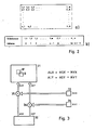
- FIGS. 3 and 4 show one of possible assignments of the coordinates of the picture elements to the addresses.
- the address of a picture element at the beginning of a line follows the address of the last picture element of the previous line. Since the memories 16 and 17 (FIG. 1) are addressed in the same way, for the sake of clarity, only an image memory 31 is shown in FIGS. 3 and 4, which is temporarily the image memory 16 or the image memory 17.
- the remaining parts of the block diagrams according to FIGS. 3 and 4 are elements of the address logic 22 (FIG. 1) insofar as their representation is necessary to understand the invention.
- the picture elements belonging to a block B are stored under addresses which are referred to below as the source addresses.
- the address addresses belonging to these picture elements are generated one after the other by an address generator 32.
- the source addresses consist of two components, ASX and ASY. If the motion estimator 21 (FIG. 1) detects a movement of the image content through which the content of block B appears in block B 'in the subsequent image, block B' is to be read out and fed to the subtracting circuit. For this purpose, two components MVX and MVY of a motion vector are generated by the motion estimator 21 and fed to the inputs 33, 34 (FIG. 3).
- Each of these components is added to a component of the source addresses ASX, ASY to form the read addresses ALX, ALY in accordance with the equations given in FIG. 3 in an adder circuit 35, 36, the sign being taken into account in accordance with the direction of movement.
- an image memory 37 is provided, which is set up for continuous addressing. To address a picture element in each case, therefore, only an address AS or AL is supplied to the picture memory 37 from a correspondingly configured address generator 38.
- a value AM is added to the source addresses AS in the adder 39, which corresponds to the offset of the block B' relative to the block B. This value is determined from the components MVX and MVY according to the given equation in a recoder 40.
- a read-only memory is advantageously suitable for this purpose, to which the components MVX and MVY are supplied as addresses, under which the respective value of AM is stored.
- Z is the number of picture elements per line and is, for example, 352.
- Block B is divided into four sub-areas T1 to T4.
- Block B consists of 16 picture elements, the center points of which are shown as circles in FIG. 5.
- Four picture elements each form one of the partial areas.
- the inputs 33, 34 are each supplied with the one of the motion vectors that describes the motion of the image element to be read out in chronological order.
Landscapes
- Engineering & Computer Science (AREA)
- Multimedia (AREA)
- Signal Processing (AREA)
- Compression Or Coding Systems Of Tv Signals (AREA)
- Closed-Circuit Television Systems (AREA)
- Color Television Systems (AREA)
Applications Claiming Priority (2)
| Application Number | Priority Date | Filing Date | Title |
|---|---|---|---|
| DE3835368 | 1988-10-18 | ||
| DE3835368A DE3835368A1 (de) | 1988-10-18 | 1988-10-18 | Schaltungsanordnung zum auslesen von daten aus einem bildspeicher |
Publications (2)
| Publication Number | Publication Date |
|---|---|
| EP0364748A2 true EP0364748A2 (fr) | 1990-04-25 |
| EP0364748A3 EP0364748A3 (fr) | 1991-03-27 |
Family
ID=6365323
Family Applications (1)
| Application Number | Title | Priority Date | Filing Date |
|---|---|---|---|
| EP19890117349 Withdrawn EP0364748A3 (fr) | 1988-10-18 | 1989-09-20 | Circuit pour lire des données d'une mémoire d'image |
Country Status (2)
| Country | Link |
|---|---|
| EP (1) | EP0364748A3 (fr) |
| DE (1) | DE3835368A1 (fr) |
Cited By (7)
| Publication number | Priority date | Publication date | Assignee | Title |
|---|---|---|---|---|
| EP0578290A1 (fr) * | 1992-05-06 | 1994-01-12 | Koninklijke Philips Electronics N.V. | Evaluation de mouvement |
| EP0613299A3 (fr) * | 1993-02-25 | 1995-02-15 | Ind Tech Res Inst | Architecture à bus dual pour la compensation de mouvement. |
| EP0633700A3 (fr) * | 1993-07-05 | 1995-04-19 | Nokia Oy Ab | Méthode et dispositif pour la recherche d'un bloc de prédiction dans une compression vidéo prédictive. |
| EP0805596A1 (fr) * | 1990-11-30 | 1997-11-05 | Sony Corporation | Détection de vecteur de mouvement et appareil de compression de bandes |
| EP0688135A3 (fr) * | 1994-06-14 | 1997-11-19 | Daewoo Electronics Co., Ltd | Appareil pour le décodage en parallèle de signaux vidéo numériques |
| EP0714211A3 (fr) * | 1994-11-21 | 1998-10-07 | SICAN, GESELLSCHAFT FÜR SILIZIUM-ANWENDUNGEN UND CAD/CAT NIEDERSACHSEN mbH | Méthode et circuit d'adressage de composantes de données d'image numériques organisées sous forme de blocs dans une mémoire adressée par page |
| CN1083217C (zh) * | 1995-06-19 | 2002-04-17 | 三星电子株式会社 | 用运动补偿复原图像信号的电路 |
Family Cites Families (3)
| Publication number | Priority date | Publication date | Assignee | Title |
|---|---|---|---|---|
| JPS6075184A (ja) * | 1983-09-30 | 1985-04-27 | Nec Corp | 動画像信号の符号化方式とその装置 |
| JPS60189388A (ja) * | 1984-03-09 | 1985-09-26 | Fujitsu Ltd | 動き補償符号化装置 |
| JPS6247786A (ja) * | 1985-08-27 | 1987-03-02 | Hamamatsu Photonics Kk | 近傍画像処理専用メモリ |
-
1988
- 1988-10-18 DE DE3835368A patent/DE3835368A1/de not_active Withdrawn
-
1989
- 1989-09-20 EP EP19890117349 patent/EP0364748A3/fr not_active Withdrawn
Cited By (8)
| Publication number | Priority date | Publication date | Assignee | Title |
|---|---|---|---|---|
| EP0805596A1 (fr) * | 1990-11-30 | 1997-11-05 | Sony Corporation | Détection de vecteur de mouvement et appareil de compression de bandes |
| EP0578290A1 (fr) * | 1992-05-06 | 1994-01-12 | Koninklijke Philips Electronics N.V. | Evaluation de mouvement |
| EP0613299A3 (fr) * | 1993-02-25 | 1995-02-15 | Ind Tech Res Inst | Architecture à bus dual pour la compensation de mouvement. |
| US5485214A (en) * | 1993-02-25 | 1996-01-16 | Industrial Technology Research Institute | Dual bus dual bank architecture for motion compensation |
| EP0633700A3 (fr) * | 1993-07-05 | 1995-04-19 | Nokia Oy Ab | Méthode et dispositif pour la recherche d'un bloc de prédiction dans une compression vidéo prédictive. |
| EP0688135A3 (fr) * | 1994-06-14 | 1997-11-19 | Daewoo Electronics Co., Ltd | Appareil pour le décodage en parallèle de signaux vidéo numériques |
| EP0714211A3 (fr) * | 1994-11-21 | 1998-10-07 | SICAN, GESELLSCHAFT FÜR SILIZIUM-ANWENDUNGEN UND CAD/CAT NIEDERSACHSEN mbH | Méthode et circuit d'adressage de composantes de données d'image numériques organisées sous forme de blocs dans une mémoire adressée par page |
| CN1083217C (zh) * | 1995-06-19 | 2002-04-17 | 三星电子株式会社 | 用运动补偿复原图像信号的电路 |
Also Published As
| Publication number | Publication date |
|---|---|
| DE3835368A1 (de) | 1990-04-19 |
| EP0364748A3 (fr) | 1991-03-27 |
Similar Documents
| Publication | Publication Date | Title |
|---|---|---|
| DE3871998T2 (de) | Fernsehsystem, in dem digitalisierte transformationskodierte bildsignale von einer kodierstation zu einer dekodierstation uebertragen werden. | |
| DE69822607T2 (de) | Nichtlinearer quantisierer für videokodierung | |
| EP0309669B1 (fr) | Procédé de réduction de données d'images se basant sur des modèles de scènes pour signaux de télévision numériques | |
| DE69220975T2 (de) | Kodierschaltung zur Transformationskodierung eines Bildsignals und Dekodierschaltung zum Dekodieren desselben | |
| DE69331939T2 (de) | Kodierungssystem | |
| EP0368139B1 (fr) | Méthode de codage d'images fautives restantes | |
| DE69831886T2 (de) | Verfahren und Vorrichtung zur Bildsignalumsetzung | |
| DE69522861T2 (de) | Verfahren und Einrichtung zur Codeumwandlung von codiertem Datenstrom | |
| DE69133024T2 (de) | System und Methode zur Kodierung von Videosignalen | |
| DE68922610T2 (de) | Umfassendes System zur Codierung und Übertragung von Videosignalen mit Bewegungsvektoren. | |
| DE69312124T2 (de) | Videocodec, insbesondere für ein Bildtelefon | |
| DE69323156T2 (de) | Bilddatenkomprimierungs/Dekomprimierungssystem | |
| DE69712836T2 (de) | Vorrichtung und verfahren zur videosignalkodierung | |
| EP0285902A2 (fr) | Procédé pour la réduction de données de séquences numérisées d'images | |
| EP0346766A1 (fr) | Procédé pour la réduction d'artefacts d'enconbrement dans le codage de scène de vidéo par transformation en cosinus discrète avec débit de données réduit | |
| DE69711736T2 (de) | Adaptive Postfilterung für ein Bildfernsprechsystem mit niedriger Bitrate | |
| DE2913404A1 (de) | Digitale schaltungsanordnung zur herbeifuehrung eines darstellungseffektes bei der wiedergabe eines video- signals | |
| EP0364748A2 (fr) | Circuit pour lire des données d'une mémoire d'image | |
| EP0363677A2 (fr) | Circuit pour l'estimation de mouvement dans une image détectée | |
| EP0366919B1 (fr) | Filtre numérique bidimensionnel | |
| EP0366976B1 (fr) | Circuit pour transformée | |
| EP0336510B1 (fr) | Codeur predictif d'image immobile | |
| DE68908254T2 (de) | Fernsehübertragungssystem mit differentieller Kodierung von Transformationskoeffizienten. | |
| EP0613302B1 (fr) | Décodeur vidéo avec unité de commande | |
| DE3839642A1 (de) | Einrichtung zur codierung von videosignalen |
Legal Events
| Date | Code | Title | Description |
|---|---|---|---|
| PUAI | Public reference made under article 153(3) epc to a published international application that has entered the european phase |
Free format text: ORIGINAL CODE: 0009012 |
|
| AK | Designated contracting states |
Kind code of ref document: A2 Designated state(s): AT CH DE ES FR GB IT LI SE |
|
| PUAL | Search report despatched |
Free format text: ORIGINAL CODE: 0009013 |
|
| AK | Designated contracting states |
Kind code of ref document: A3 Designated state(s): AT CH DE ES FR GB IT LI SE |
|
| 17P | Request for examination filed |
Effective date: 19910911 |
|
| RAP3 | Party data changed (applicant data changed or rights of an application transferred) |
Owner name: ROBERT BOSCH GMBH |
|
| STAA | Information on the status of an ep patent application or granted ep patent |
Free format text: STATUS: THE APPLICATION HAS BEEN WITHDRAWN |
|
| 17Q | First examination report despatched |
Effective date: 19930708 |
|
| 18W | Application withdrawn |
Withdrawal date: 19930724 |