EP0364821A2 - Adaptateur d'outil pour une broche de machine-outil - Google Patents
Adaptateur d'outil pour une broche de machine-outil Download PDFInfo
- Publication number
- EP0364821A2 EP0364821A2 EP89118471A EP89118471A EP0364821A2 EP 0364821 A2 EP0364821 A2 EP 0364821A2 EP 89118471 A EP89118471 A EP 89118471A EP 89118471 A EP89118471 A EP 89118471A EP 0364821 A2 EP0364821 A2 EP 0364821A2
- Authority
- EP
- European Patent Office
- Prior art keywords
- tool
- adapter
- spindle
- head
- adapter according
- Prior art date
- Legal status (The legal status is an assumption and is not a legal conclusion. Google has not performed a legal analysis and makes no representation as to the accuracy of the status listed.)
- Withdrawn
Links
- 210000002105 tongue Anatomy 0.000 claims abstract description 26
- 241000283690 Bos taurus Species 0.000 claims 1
- 238000013461 design Methods 0.000 description 2
- 238000003754 machining Methods 0.000 description 2
- 210000000080 chela (arthropods) Anatomy 0.000 description 1
- 238000006243 chemical reaction Methods 0.000 description 1
- 238000011161 development Methods 0.000 description 1
- 238000005553 drilling Methods 0.000 description 1
- 230000000694 effects Effects 0.000 description 1
- 238000005516 engineering process Methods 0.000 description 1
- 238000003780 insertion Methods 0.000 description 1
- 230000037431 insertion Effects 0.000 description 1
- 238000009434 installation Methods 0.000 description 1
- 230000003993 interaction Effects 0.000 description 1
- 230000007246 mechanism Effects 0.000 description 1
- 238000000034 method Methods 0.000 description 1
- 238000003801 milling Methods 0.000 description 1
- 238000012549 training Methods 0.000 description 1
Images


Classifications
-
- B—PERFORMING OPERATIONS; TRANSPORTING
- B23—MACHINE TOOLS; METAL-WORKING NOT OTHERWISE PROVIDED FOR
- B23B—TURNING; BORING
- B23B31/00—Chucks; Expansion mandrels; Adaptations thereof for remote control
- B23B31/02—Chucks
- B23B31/24—Chucks characterised by features relating primarily to remote control of the gripping means
- B23B31/26—Chucks characterised by features relating primarily to remote control of the gripping means using mechanical transmission through the working-spindle
- B23B31/261—Chucks characterised by features relating primarily to remote control of the gripping means using mechanical transmission through the working-spindle clamping the end of the toolholder shank
-
- B—PERFORMING OPERATIONS; TRANSPORTING
- B23—MACHINE TOOLS; METAL-WORKING NOT OTHERWISE PROVIDED FOR
- B23B—TURNING; BORING
- B23B31/00—Chucks; Expansion mandrels; Adaptations thereof for remote control
- B23B31/006—Conical shanks of tools
-
- B—PERFORMING OPERATIONS; TRANSPORTING
- B23—MACHINE TOOLS; METAL-WORKING NOT OTHERWISE PROVIDED FOR
- B23B—TURNING; BORING
- B23B2231/00—Details of chucks, toolholder shanks or tool shanks
- B23B2231/04—Adapters
-
- B—PERFORMING OPERATIONS; TRANSPORTING
- B23—MACHINE TOOLS; METAL-WORKING NOT OTHERWISE PROVIDED FOR
- B23B—TURNING; BORING
- B23B2270/00—Details of turning, boring or drilling machines, processes or tools not otherwise provided for
- B23B2270/20—Internally located features, machining or gripping of internal surfaces
-
- Y—GENERAL TAGGING OF NEW TECHNOLOGICAL DEVELOPMENTS; GENERAL TAGGING OF CROSS-SECTIONAL TECHNOLOGIES SPANNING OVER SEVERAL SECTIONS OF THE IPC; TECHNICAL SUBJECTS COVERED BY FORMER USPC CROSS-REFERENCE ART COLLECTIONS [XRACs] AND DIGESTS
- Y10—TECHNICAL SUBJECTS COVERED BY FORMER USPC
- Y10T—TECHNICAL SUBJECTS COVERED BY FORMER US CLASSIFICATION
- Y10T279/00—Chucks or sockets
- Y10T279/17—Socket type
- Y10T279/17128—Self-grasping
- Y10T279/17136—Yielding grasping jaws
- Y10T279/17145—Ball or roller
-
- Y—GENERAL TAGGING OF NEW TECHNOLOGICAL DEVELOPMENTS; GENERAL TAGGING OF CROSS-SECTIONAL TECHNOLOGIES SPANNING OVER SEVERAL SECTIONS OF THE IPC; TECHNICAL SUBJECTS COVERED BY FORMER USPC CROSS-REFERENCE ART COLLECTIONS [XRACs] AND DIGESTS
- Y10—TECHNICAL SUBJECTS COVERED BY FORMER USPC
- Y10T—TECHNICAL SUBJECTS COVERED BY FORMER US CLASSIFICATION
- Y10T279/00—Chucks or sockets
- Y10T279/17—Socket type
- Y10T279/17666—Radially reciprocating jaws
- Y10T279/17692—Moving-cam actuator
- Y10T279/17743—Reciprocating cam sleeve
- Y10T279/17752—Ball or roller jaws
-
- Y—GENERAL TAGGING OF NEW TECHNOLOGICAL DEVELOPMENTS; GENERAL TAGGING OF CROSS-SECTIONAL TECHNOLOGIES SPANNING OVER SEVERAL SECTIONS OF THE IPC; TECHNICAL SUBJECTS COVERED BY FORMER USPC CROSS-REFERENCE ART COLLECTIONS [XRACs] AND DIGESTS
- Y10—TECHNICAL SUBJECTS COVERED BY FORMER USPC
- Y10T—TECHNICAL SUBJECTS COVERED BY FORMER US CLASSIFICATION
- Y10T279/00—Chucks or sockets
- Y10T279/34—Accessory or component
- Y10T279/3406—Adapter
-
- Y—GENERAL TAGGING OF NEW TECHNOLOGICAL DEVELOPMENTS; GENERAL TAGGING OF CROSS-SECTIONAL TECHNOLOGIES SPANNING OVER SEVERAL SECTIONS OF THE IPC; TECHNICAL SUBJECTS COVERED BY FORMER USPC CROSS-REFERENCE ART COLLECTIONS [XRACs] AND DIGESTS
- Y10—TECHNICAL SUBJECTS COVERED BY FORMER USPC
- Y10T—TECHNICAL SUBJECTS COVERED BY FORMER US CLASSIFICATION
- Y10T408/00—Cutting by use of rotating axially moving tool
- Y10T408/94—Tool-support
- Y10T408/95—Tool-support with tool-retaining means
-
- Y—GENERAL TAGGING OF NEW TECHNOLOGICAL DEVELOPMENTS; GENERAL TAGGING OF CROSS-SECTIONAL TECHNOLOGIES SPANNING OVER SEVERAL SECTIONS OF THE IPC; TECHNICAL SUBJECTS COVERED BY FORMER USPC CROSS-REFERENCE ART COLLECTIONS [XRACs] AND DIGESTS
- Y10—TECHNICAL SUBJECTS COVERED BY FORMER USPC
- Y10T—TECHNICAL SUBJECTS COVERED BY FORMER US CLASSIFICATION
- Y10T409/00—Gear cutting, milling, or planing
- Y10T409/30—Milling
- Y10T409/309352—Cutter spindle or spindle support
- Y10T409/309408—Cutter spindle or spindle support with cutter holder
-
- Y—GENERAL TAGGING OF NEW TECHNOLOGICAL DEVELOPMENTS; GENERAL TAGGING OF CROSS-SECTIONAL TECHNOLOGIES SPANNING OVER SEVERAL SECTIONS OF THE IPC; TECHNICAL SUBJECTS COVERED BY FORMER USPC CROSS-REFERENCE ART COLLECTIONS [XRACs] AND DIGESTS
- Y10—TECHNICAL SUBJECTS COVERED BY FORMER USPC
- Y10T—TECHNICAL SUBJECTS COVERED BY FORMER US CLASSIFICATION
- Y10T409/00—Gear cutting, milling, or planing
- Y10T409/30—Milling
- Y10T409/30952—Milling with cutter holder
Definitions
- the invention relates to a tool adapter for a machine tool spindle with a tapered receiving bore, e.g. according to DIN 2079, and with a pull rod which can be moved axially against a spring force and which carries a collet provided at the inner end of the receiving bore and an ejection pin, the tool adapter having a tapered shaft adapted to the tapered spindle receiving bore and a conical shaft on the end face of the spindle has press-on supporting body and is equipped with contact surfaces for a transport device of an automatic tool changer and a tool head holder as well as tool head clamping means.
- the machine tool spindle has the largest possible conical spindle receiving bore for receiving a tool with a correspondingly adapted taper shank, for example an ISO 60 steep taper. If you now want to clamp a tool with a smaller, eg an ISO-50 steep taper on the same machine in the spindle, an adapter is required. Incidentally, it has now become common in machine tool technology to automatically change tool heads in so-called machining centers, for which purpose it is also necessary, from case to case, to use a tool adapter to hold the modular tools in the machine tool spindle. The clamping systems required for this are known in principle from the prior art.
- a further embodiment is proposed in DE-PS 35 06 901, several locking members being provided on the supporting body of an adapter, with which the tool adapter is automatically locked to the spindle head when inserted into the spindle by means of the gripper pliers of a tool changer. This is done in that the gripper pincers brings the locking members against spring force into their unlocking position when the tool adapter is gripped and when the taper shank is inserted into the spindle receiving bore, the locking members enter the locking recesses in the spindle head.
- the invention has for its object to a tool adapter with steep taper in the shortest possible design create, which allows easy handling, conversions or extensions, such as tool spindles when changing tools and is suitable to make the entire available axial path of the collet usable for clamping the adapter.
- the object is achieved in that the tool adapter has at least one resilient tongue projecting parallel to the clamping rod and beyond the taper shank, which travels behind or traverses the collet of the spindle such that the collet when the adapter is inserted over the head of the Tension rod is closed or kept closed in this position of the adapter.
- the invention is therefore based on the new idea that the previously unusable path of the collet can be made usable by additional means without the need for major structural changes to the adapter.
- the resilient tongue or preferably the diametrically opposed resilient tongues traverse the collet when the adapter is inserted into the tapered receiving bore of the machine tool spindle, this receiving bore simultaneously serving as a rigid abutment for the resilient tongues.
- the resilient tongues are therefore preferably arranged in the unloaded state at least at their end connected to the adapter taper shank on the adapter such that they emerge from the adapter taper shank at the taper angle determined by the taper shank. This training ensures that the tongues can be inserted into the tapered receiving bore without difficulty.
- the resilient effect of the tongues is further increased by the fact that they are bent outwards in the radial direction at their free end in deviation from the cone angle mentioned.
- the contact pressure is further optimized the resilient tongues on the collet in that the free ends of the resilient tongues on their side facing the collet are shaped accordingly to the outer shape of the collet. This can also ensure that the adapter is still held by the resilient tongues when the clamping means are released, whereby the safe removal of the locked unit of the adapter with a transport head is improved.
- the resilient tongues are elastic only at their point of attachment to the adapter taper shank and, moreover, are essentially rigid.
- the adapter support body has an axially displaceable bolt which has recesses which interact with eccentric cams of a transport head when the spindle rotates.
- the adapter can preferably be tensioned or released in the radial direction by rotating the transport head by 45 ° relative to the adapter.
- the said bolt is pretensioned by a spring which drives the bolt radially outwards.
- the tension rod of the adapter is axially displaceable in a coaxial sleeve which has a radial bore through which, when the tension rod is released or not tensioned, tension elements, preferably balls, enter recesses of a transport or tool head and thereby establish the connection to the adapter taper shank.
- the tensioning elements When the tensioning rod is tensioned, the tensioning elements preferably lie in recesses in the tensioning rod and the sleeve. Balls or pins are particularly suitable as clamping elements. An easy-to-use connection of the Taper shank with the sleeve is possible via a grub screw that is inserted into a corresponding hole.
- the support body To connect the support body to the spindle head, it has axial bores or threaded bores for screwing on the face of the spindle head.
- the corresponding counter surface of the transport head is covered with a plastic ring.
- a clamping rod which projects beyond the tapered end of the taper shank and is provided with a head and is axially displaceable against a spring force in the tool adapter.
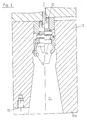
- the tool adapter 16 shown in FIGS. 1 and 3 is suitable for insertion and for clamping in machine tool spindles 10 according to FIG. 2 with a spindle head with an axial ring end face.
- the machine tool spindle 10 has a conical receiving bore 11, into which a pull rod 12, which can be displaced counter to a spring force, projects with an ejection pin 14 at the end.
- a collet 13, which is known in principle from the prior art, can also be actuated via said drawbar 12, the two possible positions of a collet arm being indicated in the left half of FIG. 2.
- the spindle head On the annular end face, the spindle head also has a threaded hole for receiving a screw, via which an adapter support body that can be attached there can be attached.
- the tool adapter 16 is shown in detail in FIG. 1 and consists essentially of a taper shank 17 and an axially arranged annular support body 18 which, when inserted, comes to face against the end face 19 of the spindle head.
- the adapter For tensioning, the adapter has a central tension rod 20 which can be moved axially in a sleeve 29 and which is prestressed by a spring 21. 1, right side of the picture, shows the position of the tensioning rod and the spring in the locked position and the left side of the picture shows a corresponding arrangement of the clamping means in the released position. The same applies to the representations in FIGS. 2 and 3.
- a plurality of diametrically opposed resilient tongues 22 are arranged at the upper end of the tapered shaft 17, the free ends of which are designed such that, when inserted in the conical receiving bore of the spindle 10, they traverse the arms of the collet 13 in such a way that they are larger than possible axial path is pressed inwards.
- the adapter cone shaft 17 is frustoconical in the present case, with resilient tongues 22 protruding from the end face of the cone shaft or being fastened there in such a way that they continue the cone angle ⁇ of the cone shaft 17 or the receiving bore 11 to form a flush end.
- the aforementioned clamping rod 20 of the adapter 16 protrudes beyond the tapered end of the tapered shaft 17 and is provided at the end with a head 23 which is embraced by the arms of the collet 13 in the clamped position. It is obvious that the quality of the clamping of the adapter 16 with the spindle 10 essentially depends on whether the greatest possible radial swivel path is covered by the clamping arms 13.
- the attachment point 24 of the resilient tongues 22 on the end face of the taper shaft 17 is designed to be elastic, while the rest of the resilient tongues should be rigid.
- the adapter 16 additionally consists of a sleeve 29 which is inserted into a central axial bore of the taper shaft 17 and is held by means of threaded pins 33 which are screwed into corresponding radial threaded bores of the taper shaft 17.
- the tension rod 20 is movable in this sleeve 29.
- a bracing of the tension rod with the sleeve can be brought about by mediation of the tensioning element 30.
- the locked position is shown in FIGS. 1 and 3 in the right half of the picture.
- the recess 32 in the tension rod is clear, in which the ball 30 rests as a tensioning element when the tension rod 20 is lowered.
- the tension rod 20 is moved upwards by spring pressure, the ball 30 falling radially outward into the recess 31 in the sleeve.
- a bolt 25 can be used by moving it radially outward into a bore 39 in the driving block 38.
- the bolt 25 is prestressed by a spring arranged in a blind hole in the sleeve, which spring tries to drive it radially outwards.
- the bolt can be guided via a eccentric cam 26, a transport head 27, the eccentric cam 26 of the transport head 27 pressing the bolts 25 outward into the bore 39 of the driving block 38 and positioning them.
- FIG. 3 An alternative fastening of the tool adapter 16 is shown in FIG. 3:
- the tool adapter is clamped with screws 35 which are screwed into bores 34 of the adapter support body 18 and the threaded bores 15 of the spindle head 10a.
- the transport head 27 is provided with a plastic ring 36, which can be glued on, for example. Furthermore, the transport head 27 also has a gripping groove 37 known from the prior art.
- the adapter according to the invention can be used as follows: The transport head 27 is inserted into the steep taper adapter 16 and clamped by the above-described interaction of the sleeve, the tension rod 20, the spring 21 and the balls 30 for installation via the gripper, not shown, in the machine tool spindle 10. The adapter 16 is then inserted into the spindle 10 together with the transport head 27. The tension rod 20 is pressed against the ejection pin of the feeder 12 and the transport head is released (FIG. 1, left side). The adapter is first held axially by the resilient tongues 22, which traverse the collet 13 from the outside, at the end of the steep taper adapter 16.
- the whole axial path of the collet 13 is made usable for the clamping of the tool adapter (see FIG. 2, dashed line, left side).
- the bolts 25 are pressed and positioned outwards into the bores 39 of the driving blocks 38 via the eccentric cams 26 of the transport head 27.
- the transport head 27 is removed and placed in the tool magazine. Tool heads in the magazine can now be clamped for machining.
- the clamping of a tool head then takes place via the pull rod 12 of the machine tool spindle 10 by means of the clamping rod 20.
- the loosening and ejection process takes place by means of a hydraulic piston, which moves the pull rod 12 out of the spindle 10 and pushes the tool head out of the tapered receiving bore 11 via the tension rod 20 of the adapter 16.
- the tool head previously gripped by the gripper pliers can be returned to the magazine.
- the adapter 16 is removed from the machine tool spindle 10 in the reverse order. With the gripper, not shown, the transport head 27 is inserted into the adapter 16. By turning the spindle 45 ° to the left, the bolts 25 are removed from the bores 39 of the driving blocks 38 via the eccentric pin 26 of the transport head 27. The ejection pin of the machine tool spindle 10 is withdrawn until the transport head 27 is tensioned via the spring 21, the tension rod 20 and the balls 30. The adapter 16 with the tensioned transport head 27 is removed, the spring force of the tongues 22 of the adapter 16 having to be overcome.
- the steep taper adapter shown in Fig. 3 is suitable for a manual change and can be used by hand and with screws 35 on the spindle head 10a be attached.
- the adapter 16 is designed with resilient tongues 22 so that the total stroke of the machine tool collet 13 can be used as a clamping path for the adapter 16.
Landscapes
- Engineering & Computer Science (AREA)
- Mechanical Engineering (AREA)
- Gripping On Spindles (AREA)
- Jigs For Machine Tools (AREA)
Applications Claiming Priority (2)
| Application Number | Priority Date | Filing Date | Title |
|---|---|---|---|
| DE3835879 | 1988-10-21 | ||
| DE3835879A DE3835879C1 (fr) | 1988-10-21 | 1988-10-21 |
Publications (2)
| Publication Number | Publication Date |
|---|---|
| EP0364821A2 true EP0364821A2 (fr) | 1990-04-25 |
| EP0364821A3 EP0364821A3 (fr) | 1990-12-27 |
Family
ID=6365618
Family Applications (1)
| Application Number | Title | Priority Date | Filing Date |
|---|---|---|---|
| EP19890118471 Withdrawn EP0364821A3 (fr) | 1988-10-21 | 1989-10-05 | Adaptateur d'outil pour une broche de machine-outil |
Country Status (4)
| Country | Link |
|---|---|
| US (1) | US4958968A (fr) |
| EP (1) | EP0364821A3 (fr) |
| JP (1) | JP2774161B2 (fr) |
| DE (1) | DE3835879C1 (fr) |
Families Citing this family (18)
| Publication number | Priority date | Publication date | Assignee | Title |
|---|---|---|---|---|
| DE4239769C2 (de) * | 1992-11-26 | 1994-09-01 | Doerries Scharmann Gmbh | Vorrichtung zum Befestigen von Werkzeugen an einer Werkzeugmaschinenspindel oder einem Werkzeughalter |
| DE4400425A1 (de) * | 1994-01-08 | 1995-07-13 | Komet Stahlhalter Werkzeug | Vorrichtung zur Kupplung zweier Werkzeugteile |
| US5771762A (en) * | 1994-04-29 | 1998-06-30 | Bissett; Kevin J. | Quick-coupling face-driver assembly of a rotary drive device and method for changing face drivers |
| JP3180870B2 (ja) * | 1994-10-25 | 2001-06-25 | 株式会社日研工作所 | 工具ホルダ |
| US5595391A (en) * | 1995-04-18 | 1997-01-21 | The Board Of Governors Of Wayne State University | Relating to tapered connections |
| DE29922642U1 (de) * | 1999-12-24 | 2000-02-24 | Röhm GmbH, 89567 Sontheim | Spannvorrichtung für einen Hohlschaft |
| US20030206780A1 (en) * | 2002-01-02 | 2003-11-06 | Hsi-Kuan Chen | Spindle assembly for a machine tool |
| JP3704320B2 (ja) * | 2002-03-18 | 2005-10-12 | 株式会社日研工作所 | 工具ホルダ |
| DE10219600C5 (de) * | 2002-05-02 | 2006-12-07 | Esa Eppinger Gmbh | Werkzeugträger mit einer Spannzangenaufnahme |
| JP2004066443A (ja) * | 2002-06-10 | 2004-03-04 | Nikken Kosakusho Works Ltd | 工具ホルダ |
| JP3899324B2 (ja) * | 2003-02-24 | 2007-03-28 | 株式会社日研工作所 | 工具ホルダ |
| DE10317097C5 (de) * | 2003-04-14 | 2017-12-14 | Vollmer Werke Maschinenfabrik Gmbh | Vorrichtung zum Einspannen von Werkzeugen oder Werkstücken |
| JP5735636B2 (ja) * | 2010-05-04 | 2015-06-17 | ザ グリーソン ワークス | スピンドルに工具を固定する工具 |
| US8292150B2 (en) | 2010-11-02 | 2012-10-23 | Tyco Healthcare Group Lp | Adapter for powered surgical devices |
| ITBS20120032A1 (it) * | 2012-03-09 | 2013-09-10 | Innse Berardi S P A | Sistema di collegamento fra un mandrino di una macchina utensile e un accessorio con attacco a cono |
| US9061355B2 (en) | 2012-06-29 | 2015-06-23 | Kennametal Inc. | Tool adaptor having an integrated damping device |
| US9630258B2 (en) | 2014-10-15 | 2017-04-25 | Kennametal Inc | Tool holder assembly with dampening elements |
| JP7702759B1 (ja) * | 2024-06-25 | 2025-07-04 | 聖杰國際股▲ふん▼有限公司 | 工作機械のツールホルダー |
Family Cites Families (10)
| Publication number | Priority date | Publication date | Assignee | Title |
|---|---|---|---|---|
| FR1356461A (fr) * | 1963-02-15 | 1964-03-27 | Telemecanique Electrique | Machine-outil multibroche de précision |
| CH512954A (it) * | 1970-01-16 | 1971-09-30 | Olivetti & Co Spa | Dispositivo di bloccaggio dell'utensile sul mandrino di una macchina utensile |
| FR2230234A5 (fr) * | 1973-05-17 | 1974-12-13 | Ratier Sa Forest | |
| DE8014064U1 (de) * | 1980-05-24 | 1980-08-21 | Roehm, Guenter Horst, 7927 Sontheim | Werkzeugspanner |
| JPS59214531A (ja) * | 1983-05-18 | 1984-12-04 | N T Tool Kk | 保持具 |
| DE3504905A1 (de) * | 1985-02-13 | 1986-08-14 | J. Kühn GmbH & Co Präzisionswerkzeug KG, 4270 Dorsten | Werkzeughalter o.dgl. |
| JPS61188041A (ja) * | 1985-02-16 | 1986-08-21 | Mori Tekkosho:Kk | 工作機械用の親子ツ−ルシヤンク |
| DE3506901A1 (de) * | 1985-02-27 | 1986-08-28 | Werkzeugmaschinenfabrik Adolf Waldrich Coburg Gmbh & Co, 8630 Coburg | Werkzeugadapter fuer eine spindel von bohr-, fraes- u.dgl. werkzeugmaschinen |
| US4747735A (en) * | 1987-01-27 | 1988-05-31 | Kennametal Inc. | Toolholder and method of releasably mounting |
| DE3734052A1 (de) * | 1987-10-08 | 1989-04-20 | Hertel Ag Werkzeuge Hartstoff | Schnellwechsel-einspannvorrichtung fuer werkzeugmaschinen |
-
1988
- 1988-10-21 DE DE3835879A patent/DE3835879C1/de not_active Expired - Lifetime
-
1989
- 1989-10-05 EP EP19890118471 patent/EP0364821A3/fr not_active Withdrawn
- 1989-10-20 JP JP1271918A patent/JP2774161B2/ja not_active Expired - Lifetime
- 1989-10-23 US US07/425,711 patent/US4958968A/en not_active Expired - Lifetime
Also Published As
| Publication number | Publication date |
|---|---|
| JP2774161B2 (ja) | 1998-07-09 |
| US4958968A (en) | 1990-09-25 |
| EP0364821A3 (fr) | 1990-12-27 |
| DE3835879C1 (fr) | 1990-01-25 |
| JPH02243209A (ja) | 1990-09-27 |
Similar Documents
| Publication | Publication Date | Title |
|---|---|---|
| DE3835879C1 (fr) | ||
| DE3007440C2 (fr) | ||
| EP0791427B1 (fr) | Dispositif de préhension pour pièces | |
| DE3504905C2 (fr) | ||
| EP0215283B1 (fr) | Accouplement d'outil | |
| DE3030909C2 (fr) | ||
| DE3506901C2 (fr) | ||
| DE4028775C1 (fr) | ||
| DE3744547A1 (de) | Schnellwechsel-spindelspannhuelse fuer werkzeughalter | |
| DE3937570C2 (fr) | ||
| EP0125434A2 (fr) | Machine-outil avec dispositif de changement d'outil | |
| EP0409973A1 (fr) | Accouplement pour la fixation amovible de pieces sur des parties de support correspondantes. | |
| DE3418615C2 (de) | Werkzeughalteeinrichtung | |
| DE4423932B4 (de) | Vorrichtung zum Schnellwechseln eines Spannzeugs einer Werkzeugmaschine | |
| EP0339282A2 (fr) | Dispositif pour serrer un outil de serrage actionné mécaniquement sur une broche de machine-outil | |
| EP0287777B1 (fr) | Dispositif de serrage d'outils ou de pièces, ayant une manche cylindrique | |
| DE69700028T2 (de) | Spannvorrichtung für Werkzeughalter mit Hohlkonus | |
| DE69308053T2 (de) | Vorrichtung für die Hauptspindel einer Werkzeugmaschine | |
| DE19818148B4 (de) | Spannvorrichtung | |
| DE69215905T2 (de) | Spannvorrichtung für fräser oder ähnliche, anpassbar für verschiedene haltergrössen | |
| DE2647633A1 (de) | Werkzeughalter | |
| DE4239769C2 (de) | Vorrichtung zum Befestigen von Werkzeugen an einer Werkzeugmaschinenspindel oder einem Werkzeughalter | |
| DE3509922C1 (de) | Spannvorrichtung zum Befestigen eines Werkstückhalters oder dergleichen an einer Spindel | |
| DE4445111C2 (de) | Vorrichtung zur Aufnahme eines Honwerkzeugs | |
| EP0118587A2 (fr) | Machine-outil avec plusieurs arbres d'usinage |
Legal Events
| Date | Code | Title | Description |
|---|---|---|---|
| PUAI | Public reference made under article 153(3) epc to a published international application that has entered the european phase |
Free format text: ORIGINAL CODE: 0009012 |
|
| AK | Designated contracting states |
Kind code of ref document: A2 Designated state(s): AT DE FR GB IT |
|
| PUAL | Search report despatched |
Free format text: ORIGINAL CODE: 0009013 |
|
| AK | Designated contracting states |
Kind code of ref document: A3 Designated state(s): AT DE FR GB IT |
|
| 17P | Request for examination filed |
Effective date: 19901129 |
|
| 17Q | First examination report despatched |
Effective date: 19920507 |
|
| STAA | Information on the status of an ep patent application or granted ep patent |
Free format text: STATUS: THE APPLICATION IS DEEMED TO BE WITHDRAWN |
|
| 18D | Application deemed to be withdrawn |
Effective date: 19930424 |