EP0364974A2 - In Azimut und Elevation verstellbare Antennenhalterung - Google Patents
In Azimut und Elevation verstellbare Antennenhalterung Download PDFInfo
- Publication number
- EP0364974A2 EP0364974A2 EP89119297A EP89119297A EP0364974A2 EP 0364974 A2 EP0364974 A2 EP 0364974A2 EP 89119297 A EP89119297 A EP 89119297A EP 89119297 A EP89119297 A EP 89119297A EP 0364974 A2 EP0364974 A2 EP 0364974A2
- Authority
- EP
- European Patent Office
- Prior art keywords
- antenna
- base
- collar
- antenna support
- collars
- Prior art date
- Legal status (The legal status is an assumption and is not a legal conclusion. Google has not performed a legal analysis and makes no representation as to the accuracy of the status listed.)
- Granted
Links
Images


Classifications
-
- H—ELECTRICITY
- H01—ELECTRIC ELEMENTS
- H01Q—ANTENNAS, i.e. RADIO AERIALS
- H01Q1/00—Details of, or arrangements associated with, antennas
- H01Q1/12—Supports; Mounting means
- H01Q1/125—Means for positioning
Definitions
- the present invention relates to an antenna mount and, more particularly, to an azimuth-elevation type mount, that is to say a mount having a vertical axis of rotation, for orienting the antenna in azimuth, and a horizontal axis of rotation, for the orientation of the antenna in elevation.
- the invention relates more specifically to an antenna of the azimuth-elevation type cantilevered with respect to the vertical axis.
- the antenna support a part mounted on a vertical base and allowing the antenna to rotate in azimuth poses a problem. Indeed, it must be able to be made free from the base, in order to allow rotation. It must then be secured to the base, in order to prevent any rotation in azimuth of the correctly pointed antenna. From one to the other of these two situations, the angle of elevation of the antenna must not change. Without this, any correction of the azimuth would also require a resumption of the elevation, which would considerably complicate the work of the antenna installer.
- An antenna support constituted, in a conventional manner, essentially by a split cylindrical piece, could not meet this need because any play brought to allow rotation in azimuth would result in a tilting of the cylindrical piece relative to the base and therefore by a displacement in elevation.
- the invention therefore relates to an antenna support comprising means such that the elevation of the antenna remains the same, whether it is free or secured to the base.
- the antenna support comprises a mounting plate to which the antenna is fixed and a barrel
- said barrel comprises at least one upper half-collar embracing the base and the arms of which are extend towards the antenna and an upper flange attaching to the upper half-collar to block it on the base, a lower half-collar embracing the base and the arms of which extend in the opposite direction to the antenna and a lower flange which attaches to the lower half-collar to block it on the base, as well as two lateral uprights of sufficient length extending at a certain distance parallel to the axis of the base and each joining, respectively, the end part of an arm of the half-collar higher than the end part located below the preceding one of the half lower collar.
- each of the half-collars embraces the base approximately 180 °.
- each of the half-collars internally comprises at least one cylindrical bearing surface of limited angular width and height.
- each of the half-collars comprises two cylindrical bearings symmetrically disposed with respect to its arms and spaced about 90 ° apart.
- the support apart from the two flanges, is made essentially of a molded metal part and, of the half-collars, only said bearings are machined.
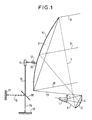
- the antenna proper comprises a source 1 illuminating an auxiliary reflector 2, which illuminates a main reflector 3.
- the curvature and the dimensions of the reflection surfaces 4 and 5 are such that, as far as possible, the auxiliary reflector 2 receives all of the radiation 6-6 ′ coming from the source 1 and distributes it in a uniform radiation 7-7 ′ over the entire surface of the main reflector 3, which generates a parallel beam 8-8 ′ having the best polarization characteristics.
- the antenna radiation axis 9 is fixed relative to these elements, the relative positions of which, for a given antenna, are also fixed.
- the pointing of the antenna therefore amounts to moving a unitary structure comprising the two reflectors and the source, thanks to an antenna mount.
- FIG. 1 illustrates an antenna mount of the type azimuth-elevation. This comprises a vertical base 10 on which is mounted an antenna support 11 which, by means of an elevation articulation 12, carries the antenna structure symbolized at 13.
- the antenna support 11 is mounted on the base 10 so as to be able to pivot relative to the vertical axis of the base.
- the antenna can thus rotate in a horizontal plane, within certain limits at least. It is thus pointed in the appropriate direction. In the absence of precise geographic or magnetic references, this score generally needs to be adjusted on site.
- the antenna structure 13 is mounted on the antenna support 11 by means of an articulation 12 allowing rotation on a horizontal axis.
- the antenna can thus be pointed with the desired elevation. This is generally known with precision, when the antenna must be pointed at a specific traffic satellite.
- the base 10 can be extended in a rectilinear manner by a leg 14 resting on a horizontal support 15. It can also be extended by a substantially horizontal leg 16 fixed to a vertical support 17. The junction of the base 10 with the leg 16 can be carried out by a double flange 18 at 45 °. The base 10 is thus fixed to any available support so that its axis is strictly vertical.
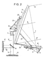
- the antenna support must allow the antenna to rotate in azimuth, then block it in the chosen azimuth, without the elevation be changed.
- Source 1 is carried by an assembly comprising two legs 20 at the lowest part of the main reflector 3 and two legs 21 also apart. At the ends of the legs 20 is fixed the auxiliary reflector 2, in the appropriate orientation.
- the surface 5 of the main reflector 3 is carried by a trellis, not shown, to which the structure 13 is fixed.
- This structure is carried by the antenna support, to which it is fixed at three points: it pivots at two points forming an elevation articulation 12 and, at another articulation point 22, it is connected by a tie 23 to an attachment 24 of the antenna support 11.
- the tie 23 is of adjustable length and defines by its length the angle of elevation of the antenna.
- FIG. 3 and 4 show in more detail the composition of the antenna support of the invention. That includes two assembled parts, a cap 30 and a barrel 31.
- the barrel 31 comprises a sole 40, on which the cap 30 is fixed, an upper half-collar 41, embracing the base 10 and whose arms 46 extend towards the antenna, and an upper flange 42 fixing to the upper half-collar 41 to block it on the base 10, a lower half-collar 43, embracing the base 10 and whose arms 47 extend in the opposite direction to the antenna, and a lower flange 44 attaching to the lower half-collar 43 to block it on the base 10, as well as two lateral uprights 45 extending over a certain distance parallel to the axis of the base and joining respectively the end part of an arm 46 of the upper half-collar 41 to the end part of an arm 47 located below the preceding part of the lower half-collar 43.
- the flange 42 is fixed to the half-collar 41 by means of vis-à-vis ears which these two parts comprise and which are joined together, for example by bolting.
- the geometry of the two parts is such that the assembly can enclose the base 10. The bolts are loose, the assembly is not opposed to rotation.
- the flange 44 and the half-collar 43 are arranged in the same way.
- the antenna support covers the upper end of the base 10.
- the load is on the side of the joint 12. It pulls the half-collar 41 towards the surface of the base 10 On this fulcrum, it pushes the half-collar 43 towards the opposite surface of the base 10. Whether the flanges are tight or not, this defines the position of the antenna support and therefore the angle of elevation of the antenna.
- the uprights 45 are not in contact with the base and do not intervene in the above.
- FIG. 5 indicates where the planes of the sections of FIGS. 6 and 7 are found.
- the sole 40 includes cells 48, for lightening the part.
- the half-collar 43 also carries a rib serving as a fulcrum for the azimuth rotation of the antenna.
- the half-collars 41 and 43 are rotated in opposite directions.
- the half-collar 41 is a part of semi-circular shape embracing the base 10 over 180 ° at most and whose arms 46 are extended by ears 50 supported by at least one reinforcing veil 51. These ears are pierced at 52 for the passage of the already mentioned tightening bolt.
- the flange 42 not shown is conventionally a bridge coming to bear on the base 10 in the center of its free part between the arms of the half-collar and which ends on either side by ears appearing opposite and at distance from the ears 50.
- FIG. 6 also shows the cylindrical bearing surfaces 52 and 53 by means of which the half-collar 41 rests on the base 10.
- These bearing surfaces are internal projections of reduced angular width, 30 ° for example, by a height limited, less than that of the half-collar, for example, and the cylindrical surface of which can be machined after molding, in order to improve the surface condition and the dimensional accuracy.
- two bearing surfaces are provided symmetrically arranged with respect to the direction opposite to the antenna, spaced apart for example by 60 °.
- FIG. 7 The lower half of FIG. 7, corresponding to the DD section, shows that, although this is not necessary, the half-collar 43 is similar in all respects to that of FIG. 6, the ears 54, veil 56, worn 56 being counterparts of parts 50, 51, 52 already described.
- the upper half of this same figure 7 is a section along the line CC, just above the half-collar 43.
- the position of the support is only defined by the bearings 51, 52, 56 which are supported on the base.
- the rigidity of the uprights 45 combined with the precision of the bearing surfaces makes it possible to precisely define the antenna elevation and to guarantee it permanently, whether the antenna support is free to rotate or, on the contrary, released by the loosening of the flanges.
- the antenna support will advantageously be produced in the form of a single molded part of which, as indicated, only the cylindrical surfaces of the surfaces will be machined.
Landscapes
- Support Of Aerials (AREA)
- Variable-Direction Aerials And Aerial Arrays (AREA)
Applications Claiming Priority (2)
| Application Number | Priority Date | Filing Date | Title |
|---|---|---|---|
| FR8813825 | 1988-10-21 | ||
| FR8813825A FR2640086B1 (fr) | 1988-10-21 | 1988-10-21 | Support d'antenne de type azimut-elevation |
Publications (3)
| Publication Number | Publication Date |
|---|---|
| EP0364974A2 true EP0364974A2 (de) | 1990-04-25 |
| EP0364974A3 EP0364974A3 (de) | 1991-05-15 |
| EP0364974B1 EP0364974B1 (de) | 1995-02-01 |
Family
ID=9371198
Family Applications (1)
| Application Number | Title | Priority Date | Filing Date |
|---|---|---|---|
| EP89119297A Expired - Lifetime EP0364974B1 (de) | 1988-10-21 | 1989-10-17 | In Azimut und Elevation verstellbare Antennenhalterung |
Country Status (5)
| Country | Link |
|---|---|
| US (1) | US5000408A (de) |
| EP (1) | EP0364974B1 (de) |
| DE (1) | DE68920942T2 (de) |
| ES (1) | ES2067511T3 (de) |
| FR (1) | FR2640086B1 (de) |
Cited By (1)
| Publication number | Priority date | Publication date | Assignee | Title |
|---|---|---|---|---|
| ES2039164A2 (es) * | 1992-01-30 | 1993-08-16 | Sener Ing & Sist | Mecanismo de ajuste de alta precision para el posicionado correcto de estructuras deformables. |
Families Citing this family (6)
| Publication number | Priority date | Publication date | Assignee | Title |
|---|---|---|---|---|
| NL9201609A (nl) * | 1992-09-17 | 1994-04-18 | Hollandse Signaalapparaten Bv | Inrichting voor het ruimtelijk orienteren van een object. |
| US5952980A (en) * | 1997-09-17 | 1999-09-14 | Bei Sensors & Motion Systems Company | Low profile antenna positioning system |
| US7173575B2 (en) * | 2005-01-26 | 2007-02-06 | Andrew Corporation | Reflector antenna support structure |
| US7439930B2 (en) * | 2005-03-23 | 2008-10-21 | Asc Signal Corporation | Antenna mount with fine adjustment cam |
| US7196675B2 (en) * | 2005-03-24 | 2007-03-27 | Andrew Corporation | High resolution orientation adjusting arrangement for feed assembly |
| US7046210B1 (en) | 2005-03-30 | 2006-05-16 | Andrew Corporation | Precision adjustment antenna mount and alignment method |
Family Cites Families (12)
| Publication number | Priority date | Publication date | Assignee | Title |
|---|---|---|---|---|
| LU34597A1 (de) * | 1955-08-25 | |||
| US3167292A (en) * | 1963-12-12 | 1965-01-26 | Nathan L Meyerowitz | Bracket |
| US3391889A (en) * | 1966-06-07 | 1968-07-09 | Cocker Machine & Foundry Compa | Yarn package holder for textile creels |
| DE1986271U (de) * | 1968-03-15 | 1968-05-30 | Merkur Gmbh Metallwerk | Vorrichtung zum befestigen von platten, schildern od. dgl., insbesondere verkehrsschildern. |
| DE3127855A1 (de) * | 1981-07-15 | 1983-06-30 | AEG-Telefunken Nachrichtentechnik GmbH, 7150 Backnang | Halterung fuer eine in azimut- und elevationsrichtung schwenkbare parabolantenne |
| JPS6075103A (ja) * | 1983-09-30 | 1985-04-27 | Matsushita Electric Ind Co Ltd | パラボラアンテナの取付装置 |
| US4626864A (en) * | 1984-03-12 | 1986-12-02 | Polarmax Corporation | Motorized antenna mount for satellite dish |
| US4617572A (en) * | 1984-08-14 | 1986-10-14 | Albert Hugo | Television dish antenna mounting structure |
| DE3530809A1 (de) * | 1985-08-29 | 1987-03-05 | Kolbe & Co Hans | Parabolspiegelantenne |
| US4659044A (en) * | 1985-09-26 | 1987-04-21 | Armstrong Douglas C | Universal kit for spar-mounted mount for radar antenna |
| FR2595510B1 (fr) * | 1986-03-04 | 1988-09-16 | Const Centre Atel | Support d'antenne de reception |
| US4819007A (en) * | 1987-06-22 | 1989-04-04 | Andrew Corporation | Supporting structure for reflector-type microwave antennas |
-
1988
- 1988-10-21 FR FR8813825A patent/FR2640086B1/fr not_active Expired - Lifetime
-
1989
- 1989-10-17 ES ES89119297T patent/ES2067511T3/es not_active Expired - Lifetime
- 1989-10-17 DE DE68920942T patent/DE68920942T2/de not_active Expired - Fee Related
- 1989-10-17 EP EP89119297A patent/EP0364974B1/de not_active Expired - Lifetime
- 1989-10-23 US US07/425,131 patent/US5000408A/en not_active Expired - Fee Related
Cited By (1)
| Publication number | Priority date | Publication date | Assignee | Title |
|---|---|---|---|---|
| ES2039164A2 (es) * | 1992-01-30 | 1993-08-16 | Sener Ing & Sist | Mecanismo de ajuste de alta precision para el posicionado correcto de estructuras deformables. |
Also Published As
| Publication number | Publication date |
|---|---|
| ES2067511T3 (es) | 1995-04-01 |
| FR2640086B1 (fr) | 1991-01-18 |
| DE68920942T2 (de) | 1995-06-08 |
| EP0364974B1 (de) | 1995-02-01 |
| FR2640086A1 (fr) | 1990-06-08 |
| EP0364974A3 (de) | 1991-05-15 |
| DE68920942D1 (de) | 1995-03-16 |
| US5000408A (en) | 1991-03-19 |
Similar Documents
| Publication | Publication Date | Title |
|---|---|---|
| EP0082068B1 (de) | Trägerstruktur für Sonnenkollektor | |
| WO1995035476A1 (fr) | Equipement portatif pour immobiliser les armes a feu individuelles | |
| WO2002033785A1 (fr) | Mat d'antenne et dispositif pour le reglage de l'orientation d'une antenne | |
| EP0364974B1 (de) | In Azimut und Elevation verstellbare Antennenhalterung | |
| FR2793607A1 (fr) | Dispositif de montage et d'orientation en azimut/elevation d'une antenne | |
| EP0035930B1 (de) | Antennenträger zum Empfangen von Nachrichtensatellitensendungen und Antenne mit einem solchen Träger | |
| EP0114543B1 (de) | Allseitige Orientierungsvorrichtung für eine Antenne | |
| WO2004095630A1 (fr) | Monture d’antenne permettant un reglage fin de l’orientation de l’antenne | |
| FR2825516A1 (fr) | Dispositif formant mat vertical de support d'au moins une antenne de transmission d'ondes radioelectriques | |
| FR2802582A1 (fr) | Dispositif de fixation d'un equipement sur un mat | |
| CA2418233C (fr) | Dispositif de commande d'aube a angle de calage variable a liaison sans jeu | |
| FR2745423A1 (fr) | Support d'antenne | |
| EP2713435B1 (de) | Montagesystem einer Antenne auf einer zylindrischen Halterung | |
| FR2696281A1 (fr) | Monture d'antenne à pointage réglable, notamment pour antenne de télécommunications par satellite. | |
| WO2004109845A1 (fr) | Monture d’antenne permettant un reglage fin de l’orientation en azimut de l’antenne | |
| FR2975143A1 (fr) | Dispositif permettant de regler la position angulaire d'un organe, de facon a garantir la liaison de ce dernier avec un support selon un plan de contact d'orientation predeterminee. | |
| WO2009156612A2 (fr) | Ensemble pour systeme d'antenne integrant une antenne autoportante et systeme d'antenne correspondant | |
| EP0112205A1 (de) | Halterung für eine Fernsehantenne für Satellitenempfang und Einheit bestehend aus einer solchen Halterung und ihrer Antenne | |
| FR2524256A1 (fr) | Fixe-tuteur | |
| FR2533771A1 (fr) | Support de poulie de deroulage pour cable | |
| FR2913285A1 (fr) | Dispositif d'adjonction d'une tete hyperfrequence supplementaire sur une antenne de reception satellite | |
| FR2689611A1 (fr) | Dispositif de montage d'une partie de projecteur de véhicule automobile. | |
| FR2911359A1 (fr) | Systeme de crapaudine de type reglable | |
| FR2630390A1 (fr) | Ensemble-support de poulies pour installation de transport par cable aerien | |
| FR2594392A1 (fr) | Retroviseur exterieur pour vehicule, comportant des moyens d'articulation simplifies |
Legal Events
| Date | Code | Title | Description |
|---|---|---|---|
| PUAI | Public reference made under article 153(3) epc to a published international application that has entered the european phase |
Free format text: ORIGINAL CODE: 0009012 |
|
| AK | Designated contracting states |
Kind code of ref document: A2 Designated state(s): DE ES FR GB IT NL SE |
|
| PUAL | Search report despatched |
Free format text: ORIGINAL CODE: 0009013 |
|
| AK | Designated contracting states |
Kind code of ref document: A3 Designated state(s): DE ES FR GB IT NL SE |
|
| 17P | Request for examination filed |
Effective date: 19911104 |
|
| RAP1 | Party data changed (applicant data changed or rights of an application transferred) |
Owner name: ALCATEL TELSPACE |
|
| 17Q | First examination report despatched |
Effective date: 19931215 |
|
| GRAA | (expected) grant |
Free format text: ORIGINAL CODE: 0009210 |
|
| AK | Designated contracting states |
Kind code of ref document: B1 Designated state(s): DE ES FR GB IT NL SE |
|
| REF | Corresponds to: |
Ref document number: 68920942 Country of ref document: DE Date of ref document: 19950316 |
|
| REG | Reference to a national code |
Ref country code: ES Ref legal event code: FG2A Ref document number: 2067511 Country of ref document: ES Kind code of ref document: T3 |
|
| ITF | It: translation for a ep patent filed | ||
| GBT | Gb: translation of ep patent filed (gb section 77(6)(a)/1977) |
Effective date: 19950320 |
|
| PLBE | No opposition filed within time limit |
Free format text: ORIGINAL CODE: 0009261 |
|
| STAA | Information on the status of an ep patent application or granted ep patent |
Free format text: STATUS: NO OPPOSITION FILED WITHIN TIME LIMIT |
|
| 26N | No opposition filed | ||
| PGFP | Annual fee paid to national office [announced via postgrant information from national office to epo] |
Ref country code: GB Payment date: 20000915 Year of fee payment: 12 |
|
| PGFP | Annual fee paid to national office [announced via postgrant information from national office to epo] |
Ref country code: NL Payment date: 20000925 Year of fee payment: 12 |
|
| PGFP | Annual fee paid to national office [announced via postgrant information from national office to epo] |
Ref country code: SE Payment date: 20001002 Year of fee payment: 12 |
|
| PGFP | Annual fee paid to national office [announced via postgrant information from national office to epo] |
Ref country code: DE Payment date: 20001005 Year of fee payment: 12 |
|
| PGFP | Annual fee paid to national office [announced via postgrant information from national office to epo] |
Ref country code: FR Payment date: 20001012 Year of fee payment: 12 |
|
| PGFP | Annual fee paid to national office [announced via postgrant information from national office to epo] |
Ref country code: ES Payment date: 20001020 Year of fee payment: 12 |
|
| PG25 | Lapsed in a contracting state [announced via postgrant information from national office to epo] |
Ref country code: GB Free format text: LAPSE BECAUSE OF NON-PAYMENT OF DUE FEES Effective date: 20011017 |
|
| PG25 | Lapsed in a contracting state [announced via postgrant information from national office to epo] |
Ref country code: SE Free format text: LAPSE BECAUSE OF NON-PAYMENT OF DUE FEES Effective date: 20011018 Ref country code: ES Free format text: LAPSE BECAUSE OF NON-PAYMENT OF DUE FEES Effective date: 20011018 |
|
| REG | Reference to a national code |
Ref country code: GB Ref legal event code: IF02 |
|
| PG25 | Lapsed in a contracting state [announced via postgrant information from national office to epo] |
Ref country code: NL Free format text: LAPSE BECAUSE OF NON-PAYMENT OF DUE FEES Effective date: 20020501 |
|
| EUG | Se: european patent has lapsed |
Ref document number: 89119297.3 |
|
| GBPC | Gb: european patent ceased through non-payment of renewal fee |
Effective date: 20011017 |
|
| PG25 | Lapsed in a contracting state [announced via postgrant information from national office to epo] |
Ref country code: FR Free format text: LAPSE BECAUSE OF NON-PAYMENT OF DUE FEES Effective date: 20020628 |
|
| NLV4 | Nl: lapsed or anulled due to non-payment of the annual fee |
Effective date: 20020501 |
|
| PG25 | Lapsed in a contracting state [announced via postgrant information from national office to epo] |
Ref country code: DE Free format text: LAPSE BECAUSE OF NON-PAYMENT OF DUE FEES Effective date: 20020702 |
|
| REG | Reference to a national code |
Ref country code: FR Ref legal event code: ST |
|
| REG | Reference to a national code |
Ref country code: ES Ref legal event code: FD2A Effective date: 20021113 |
|
| PG25 | Lapsed in a contracting state [announced via postgrant information from national office to epo] |
Ref country code: IT Free format text: LAPSE BECAUSE OF NON-PAYMENT OF DUE FEES;WARNING: LAPSES OF ITALIAN PATENTS WITH EFFECTIVE DATE BEFORE 2007 MAY HAVE OCCURRED AT ANY TIME BEFORE 2007. THE CORRECT EFFECTIVE DATE MAY BE DIFFERENT FROM THE ONE RECORDED. Effective date: 20051017 |