EP0364985B1 - Procédé de fabrication d'un appareil de réfrigération et de congélation combiné - Google Patents
Procédé de fabrication d'un appareil de réfrigération et de congélation combiné Download PDFInfo
- Publication number
- EP0364985B1 EP0364985B1 EP89119347A EP89119347A EP0364985B1 EP 0364985 B1 EP0364985 B1 EP 0364985B1 EP 89119347 A EP89119347 A EP 89119347A EP 89119347 A EP89119347 A EP 89119347A EP 0364985 B1 EP0364985 B1 EP 0364985B1
- Authority
- EP
- European Patent Office
- Prior art keywords
- evaporator
- compartment
- refrigerating
- freezing
- freezing compartment
- Prior art date
- Legal status (The legal status is an assumption and is not a legal conclusion. Google has not performed a legal analysis and makes no representation as to the accuracy of the status listed.)
- Expired - Lifetime
Links
- 230000008014 freezing Effects 0.000 title claims description 24
- 238000007710 freezing Methods 0.000 title claims description 24
- 238000004519 manufacturing process Methods 0.000 title claims description 12
- 238000009413 insulation Methods 0.000 claims description 13
- 238000010438 heat treatment Methods 0.000 claims description 9
- 238000010257 thawing Methods 0.000 claims description 8
- 238000005187 foaming Methods 0.000 claims description 7
- 238000000034 method Methods 0.000 claims description 6
- 229920002635 polyurethane Polymers 0.000 claims description 6
- 239000004814 polyurethane Substances 0.000 claims description 6
- 239000002184 metal Substances 0.000 claims description 4
- 230000000737 periodic effect Effects 0.000 claims description 3
- 230000000694 effects Effects 0.000 claims description 2
- 239000004020 conductor Substances 0.000 claims 1
- 238000003825 pressing Methods 0.000 description 3
- 239000000853 adhesive Substances 0.000 description 2
- 230000001070 adhesive effect Effects 0.000 description 2
- 238000012856 packing Methods 0.000 description 2
- 230000002093 peripheral effect Effects 0.000 description 2
- XLYOFNOQVPJJNP-UHFFFAOYSA-N water Substances O XLYOFNOQVPJJNP-UHFFFAOYSA-N 0.000 description 2
- 238000003466 welding Methods 0.000 description 2
- 238000004026 adhesive bonding Methods 0.000 description 1
- 230000015572 biosynthetic process Effects 0.000 description 1
- 238000010276 construction Methods 0.000 description 1
- 230000002950 deficient Effects 0.000 description 1
- 238000007599 discharging Methods 0.000 description 1
- 239000011810 insulating material Substances 0.000 description 1
- 238000012423 maintenance Methods 0.000 description 1
- 230000035515 penetration Effects 0.000 description 1
- 229920003023 plastic Polymers 0.000 description 1
- 239000004033 plastic Substances 0.000 description 1
- 238000005057 refrigeration Methods 0.000 description 1
Images


Classifications
-
- F—MECHANICAL ENGINEERING; LIGHTING; HEATING; WEAPONS; BLASTING
- F25—REFRIGERATION OR COOLING; COMBINED HEATING AND REFRIGERATION SYSTEMS; HEAT PUMP SYSTEMS; MANUFACTURE OR STORAGE OF ICE; LIQUEFACTION SOLIDIFICATION OF GASES
- F25D—REFRIGERATORS; COLD ROOMS; ICE-BOXES; COOLING OR FREEZING APPARATUS NOT OTHERWISE PROVIDED FOR
- F25D23/00—General constructional features
- F25D23/06—Walls
- F25D23/062—Walls defining a cabinet
- F25D23/064—Walls defining a cabinet formed by moulding, e.g. moulding in situ
Definitions
- the present invention relates to a method for producing a combined refrigerating and freezing apparatus by which the apparatus are realized in a simple way and with fewer working steps.
- Combined refrigerating and freezing apparatus for food and in particular the "no-frost" type of apparatus, are known to comprise substantially two separate compartments one above the other, one for refrigeration and one for freezing, which are joined together during the phase of foaming the thermal insulation around said compartments, so as to obtain one cabinet extending vertically and having hinged thereto the doors for closing each compartment (see, for example, EP-A-0 161 724).
- the freezing compartment of such an apparatus is normally provided with a battery evaporator connected to the refrigerating circuit of the apparatus, and with a fan for circulating the cooled air in a closed circuit within this compartment.
- Such a battery evaporator which is normally also equipped with a heating element for defrosting, is applied with known fixing means against the back wall of the freezing compartment after the latter has been combined with the refrigerating compartment, and the end capillaries of the battery evaporator are then inserted through appropriate openings passing through the back wall of the apparatus and then fixed, preferably by welding, with the corresponding terminal pipes of the refrigerating circuit of the apparatus.
- Each apparatus of this type therefore requires further working phases to be performed after its production to mount it in position and connect the battery evaporator to the refrigerating circuit of the apparatus, which complicates and hampers the construction of such apparatus and also necessitates further operations for controlling the functionality of the refrigerating circuit after those operations normally required before connecting the battery evaporator to the circuit.
- the invention is based on the problem of overcoming the above-mentioned shortcomings and limits using a method for producing a combined refrigerating and freezing apparatus so as to obtain the apparatus in a constructionally simple way and with fewer working steps.
- This production method is based substantially on the idea of connecting the battery evaporator to the refrigerating circuit of the apparatus before assembling the two compartments of the apparatus, and of then incorporating the battery evaporator within the freezing compartment directly during the operation of foaming the thermal insulation for both the compartments.
- the features of the production method are specified in the adjoined claims.
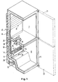
- a combined apparatus 6 for refrigerating and freezing food comprising substantially a refrigerating compartment 7 and a freezing compartment 8 which are separate, disposed one above the other, extend vertically and are contained in a parallelepiped metal cabinet 9 with a thermal insulation 10 interposed therebetween, such as e.g. expanded polyurethane or another suitable thermally insulating material.
- Compartments 7 and 8 are in particular provided, respectively, with a conventional refrigerating evaporator 11 of the "vanishing" type, i.e. adapted to be applied against the back surface of the back wall of the compartment, in which it is incorporated within thermal insulation 10, and with a refrigerating evaporator 12 equipped with a battery and fins 13 for increasing the heat exchange surface, and also having an electrical heating element for defrosting 14 disposed in contact with the outer surface of the battery evaporator and connected electrically to the electrical system of the apparatus.
- a conventional refrigerating evaporator 11 of the "vanishing" type i.e. adapted to be applied against the back surface of the back wall of the compartment, in which it is incorporated within thermal insulation 10
- a refrigerating evaporator 12 equipped with a battery and fins 13 for increasing the heat exchange surface, and also having an electrical heating element for defrosting 14 disposed in contact with the outer surface of the battery evaporator and connected electrically to the electrical system of the apparatus
- Freezing compartment 8 is furthermore provided with at least one fan 15 which is disposed In the compartment in the vicinity of battery evaporator 12 and set rotating by a traditional electrical motor 16 connected to the electrical system of the apparatus, in order to freeze the food disposed in the shelves of the compartment (which are not shown) by means of a current of cold air.
- This apparatus is referred to as "no frost" thanks to the possibility of periodically defrosting the battery evaporator by means of heating element 14.
- the present combined apparatus is finally provided with a condenser 17 and a refrigerating compressor 18 adapted to be applied respectively against the rear surface of back 19 of cabinet 9 and within a space 20 formed in the rear lower part of the cabinet, the apparatus being further provided with two doors 21 and 22 for closing the front of corresponding compartments 7 and 8, the doors being hinged to the right (or left) side of the cabinet.
- FIG. 2 shows that during the first working phase of this apparatus, which involves refrigerating compartment 7 made of plastic preformed by working techniques known as such, the compartment is placed upside down and supported on a suitable fixed support 23 or on a conveyor belt (not shown) of the production line of the apparatus.
- refrigerating evaporator 11 is applied against the outer surface of back wall 24 of compartment 7 by means of adhesives, adhesive bands or similar methods, the evaporator being preferably embodied by a pipe coil whose ends are connected beforehand, preferably by welding, to the corresponding ends of battery evaporator 12.
- the battery evaporator is provided with a return pipe 25 adapted to be connected to the corresponding intake pipe (not shown) of the refrigerating compressor (also not shown) during the assembly of the latter in the combined apparatus, at the same time as the condenser of the refrigerating circuit (the condenser not being shown either).
- This compartment is disposed adjacent the other compartment (not shown) and spaced therefrom so as to allow for the mutual assembly of the compartments during the operation of foaming the polyurethane thermal insulation of the apparatus.
- This compartment is furthermore realized with a side wall 27 which is dismountable therefrom to allow for introduction of battery evaporator 12 inside the compartment during this working phase of the apparatus.
- side wall 27 is dimensioned to fit against the corresponding peripheral edge of compartment 8 and, after the introduction of battery evaporator 12 inside the compartment, said wall is fixed with working methods known as such against the lateral edge of the compartment.
- This side wall is furthermore provided with a through hole 28 in correspondence with the above-mentioned peripheral edge, said edge having inserted therein a packing 29 provided to prevent the penetration of the thermal insulation inside compartment 8 during the foaming phase, and said packing having holes for the passage of pipes 30 and 31 for interconnecting evaporators 11 and 12.
- electrical heating element 34 adapted to effect the periodic defrosting is applied by gluing, taping or similar methods against the outer surface of conveyor 32 for collecting water during the periodic defrosting of battery evaporator 12, the conveyor being disposed below the evaporator and connected with a pipe 33 for discharging the water to the outside.
- battery evaporator 12 is applied against back wall 35 of compartment 8, as can be seen in Fig. 5, by means of screws 36 to be screwed into and out of corresponding threaded sockets 37 to be inserted through corresponding holes 38 through the back wall and equipped with appropriately bent rigid arms 39 adapted to form a stop against the corresponding surface of the back wall in order to hold sockets 37 in position before they are countersunk in thermal insulation 10, during the following phase of foaming the latter around both compartments 7 and 8, performed in the way described below.
- die 41 is provided with two separate protruding portions 43 and 44 dimensioned to fit perfectly inside corresponding refrigerating and freezing compartments 7 and 8, while punch 42 is in turn provided with a flat plate 45 dimensioned to fit the outer profile of compartments 7 and 8, being spaced from the profile to allow for formation of thermal insulation 10.
- protruding portion 44 of die 42 is also provided with a through hole 46 formed in correspondence with the position of battery evaporator 12 inside freezing compartment 8 and dimensioned to allow for a perfect fit of the battery evaporator through the hole during the introduction of aforesaid protruding portions 43 and 44 into corresponding compartments 7 and 8.
- the expanded polyurethane can be injected inside the pressing tool, thereby forming the combined apparatus whose evaporator 11 is countersunk in thermal insulation 10 and whose battery evaporator 12 with its defrosting heating element 14 is put directly in position inside freezing compartment 8.
- fan 15 with its driving motor 16 is introduced inside compartment 8, the fan being put in position by being screwed against corresponding sockets (not shown) countersunk in the thermal insulation of the apparatus, together with the sockets for the passage of cable 47 for supplying power to the motor and to the heating element for defrosting 14 (see Fig. 1). Furthermore, condenser 17 and compressor 18 are then disposed in their respective positions against the back walls of the apparatus and connected in the known way to the refrigerating circuit of the apparatus.
Landscapes
- Engineering & Computer Science (AREA)
- Chemical & Material Sciences (AREA)
- Combustion & Propulsion (AREA)
- Physics & Mathematics (AREA)
- Mechanical Engineering (AREA)
- Thermal Sciences (AREA)
- General Engineering & Computer Science (AREA)
- Devices That Are Associated With Refrigeration Equipment (AREA)
Claims (2)
- Procédé de production d'un appareil combiné de réfrigération et de congélation, comprenant un compartiment de réfrigération (7) et un compartiment de congélation (8) qui sont distincts, disposés l'un au dessus de l'autre et équipés, respectivement, d'un premier et d'un second évaporateurs de réfrigération (11, 12), le compartiment de congélation (8) étant également équipé d'au moins un ventilateur motorisé (15) et d'un élément électrique chauffant conçu pour créer, respectivement, un courant d'air froid dans le compartiment et un dégivrage périodique du second évaporateur (12), ledit procédé prévoyant l'utilisation d'au moins une matrice (41) et d'un poinçon (42) du type classique pour réaliser, par formation de mousse, une isolation thermique en polyuréthanne dans l'espace compris entre les compartiments de réfrigération et de congélation et l'habillage métallique extérieur de l'appareil, et qui est caractérisé : par une première phase dans laquelle le premier évaporateur (11) préalablement raccordé hermétiquement au second évaporateur (12) est appliqué par des moyens connus contre la paroi arrière (24) du compartiment de réfrigération (7) ; par une deuxième phase dans laquelle le second évaporateur (12) et l'élément chauffant (14) sont d'abord introduits ensemble dans le compartiment de congélation (8) au moyen d'une paroi latérale démontable (27) du compartiment, et le Second évaporateur (12) est ensuite mis en position dans le compartiment de congélation (8) par des moyens de fixation (36, 37) ; et par une troisième phase dans laquelle l'isolation thermique de polyuréthanne est réalisée par formation de mousse dans ledit espace, en noyant ainsi à l'intérieur le premier évaporateur (11) et les moyens de fixation (36, 37) du second évaporateur (12), et dans laquelle le ventilateur motorisé (15) est mis en place dans le compartiment de congélation (8) et connecté électriquement, en même temps que l'élément chauffant (14), aux moyens conducteurs (47) de l'appareil.
- Procédé de fabrication selon la revendication 1, caractérisé en ce que les moyens de fixation comprennent une pluralité de vis (36) destinées à être engagées dans des supports taraudés (37) destinés à être introduits dans des trous traversants (38) dans la paroi arrière (35) du compartiment de congélation (8), lesdits supports taraudés (37) étant pourvus de bras rigides (39) conçus pour former une butée contre la paroi arrière (35) pour maintenir le second évaporateur (12) en position.
Applications Claiming Priority (2)
| Application Number | Priority Date | Filing Date | Title |
|---|---|---|---|
| IT4576488 | 1988-10-20 | ||
| IT8845764A IT1225126B (it) | 1988-10-20 | 1988-10-20 | Procedimento di fabbricazione di apparecchiature combinate di refrigerazione e di congelazione |
Publications (3)
| Publication Number | Publication Date |
|---|---|
| EP0364985A2 EP0364985A2 (fr) | 1990-04-25 |
| EP0364985A3 EP0364985A3 (fr) | 1991-01-16 |
| EP0364985B1 true EP0364985B1 (fr) | 1993-03-31 |
Family
ID=11258118
Family Applications (1)
| Application Number | Title | Priority Date | Filing Date |
|---|---|---|---|
| EP89119347A Expired - Lifetime EP0364985B1 (fr) | 1988-10-20 | 1989-10-18 | Procédé de fabrication d'un appareil de réfrigération et de congélation combiné |
Country Status (4)
| Country | Link |
|---|---|
| EP (1) | EP0364985B1 (fr) |
| DE (1) | DE68905747T2 (fr) |
| ES (1) | ES2039797T3 (fr) |
| IT (1) | IT1225126B (fr) |
Families Citing this family (1)
| Publication number | Priority date | Publication date | Assignee | Title |
|---|---|---|---|---|
| EP2136168B1 (fr) | 2008-06-20 | 2020-01-15 | Electrolux Home Products Corporation N.V. | Condensateur d'appareil de refroidissement, et appareil de refroidissement l'incluant |
Family Cites Families (4)
| Publication number | Priority date | Publication date | Assignee | Title |
|---|---|---|---|---|
| GB864965A (en) * | 1958-03-27 | 1961-04-12 | Gen Motors Corp | Improved refrigerator cabinet, and method of making such a cabinet |
| US3966283A (en) * | 1973-06-04 | 1976-06-29 | Franklin Manufacturing Company | Refrigeration apparatus and method for making same |
| IT1173995B (it) * | 1984-05-18 | 1987-06-24 | Eurodomestici Ind Riunite | Mobile di apparecchio refrigerante con almeno due vani di conservazione e con isolamento in materiale sintetico espanso |
| US4826010A (en) * | 1987-07-31 | 1989-05-02 | White Consolidated Industries, Inc. | Refrigeration cabinet construction |
-
1988
- 1988-10-20 IT IT8845764A patent/IT1225126B/it active
-
1989
- 1989-10-18 EP EP89119347A patent/EP0364985B1/fr not_active Expired - Lifetime
- 1989-10-18 ES ES198989119347T patent/ES2039797T3/es not_active Expired - Lifetime
- 1989-10-18 DE DE8989119347T patent/DE68905747T2/de not_active Expired - Lifetime
Also Published As
| Publication number | Publication date |
|---|---|
| EP0364985A2 (fr) | 1990-04-25 |
| IT8845764A0 (it) | 1988-10-20 |
| DE68905747D1 (de) | 1993-05-06 |
| DE68905747T2 (de) | 1993-07-08 |
| IT1225126B (it) | 1990-11-02 |
| ES2039797T3 (es) | 1993-10-01 |
| EP0364985A3 (fr) | 1991-01-16 |
Similar Documents
| Publication | Publication Date | Title |
|---|---|---|
| US7051539B2 (en) | Convertible refrigerator-freezer | |
| US4332429A (en) | Household refrigerator and method of construction | |
| CA1046571A (fr) | Refrigerateur-congelateur a compartiments jumeles avec isolant mousse | |
| US4050145A (en) | Method of making refrigeration apparatus enclosure structure | |
| EP1462744B1 (fr) | Réfrigérateur | |
| US4776182A (en) | Circulating air refrigerator and power module for same | |
| US5722244A (en) | Modular ice cube maker and method of manufacture | |
| US8079231B2 (en) | Housing for a refrigerator | |
| KR20010023799A (ko) | 캐비넷, 캐비넷의 부품 및 관련 방법 | |
| US3913996A (en) | Refrigeration apparatus enclosure structure | |
| EP0334414A2 (fr) | Réfrigérateur modulaire | |
| US6574982B1 (en) | Icemaker fill tube assembly | |
| US3254503A (en) | Frost preventer for freezer apparatus | |
| US3717009A (en) | Refrigeration evaporator assembly | |
| EP0364985B1 (fr) | Procédé de fabrication d'un appareil de réfrigération et de congélation combiné | |
| US20040177637A1 (en) | Refrigerator methods and apparatus | |
| KR100202605B1 (ko) | 업소용 주문형 냉장고 | |
| JPH1194436A (ja) | 冷蔵庫 | |
| JPS6221898Y2 (fr) | ||
| US20120061051A1 (en) | Dispenser heater for an appliance | |
| CN222257165U (zh) | 制冷设备 | |
| JP2551773Y2 (ja) | 冷凍冷蔵庫 | |
| JP2005156080A (ja) | 冷蔵庫 | |
| JPS6244299Y2 (fr) | ||
| JP2635449B2 (ja) | 冷凍冷蔵庫の冷却器の構造 |
Legal Events
| Date | Code | Title | Description |
|---|---|---|---|
| PUAI | Public reference made under article 153(3) epc to a published international application that has entered the european phase |
Free format text: ORIGINAL CODE: 0009012 |
|
| AK | Designated contracting states |
Kind code of ref document: A2 Designated state(s): CH DE ES FR GB IT LI SE |
|
| PUAL | Search report despatched |
Free format text: ORIGINAL CODE: 0009013 |
|
| AK | Designated contracting states |
Kind code of ref document: A3 Designated state(s): CH DE ES FR GB IT LI SE |
|
| 17P | Request for examination filed |
Effective date: 19910102 |
|
| 17Q | First examination report despatched |
Effective date: 19920203 |
|
| ITF | It: translation for a ep patent filed | ||
| GRAA | (expected) grant |
Free format text: ORIGINAL CODE: 0009210 |
|
| AK | Designated contracting states |
Kind code of ref document: B1 Designated state(s): CH DE ES FR GB IT LI SE |
|
| REF | Corresponds to: |
Ref document number: 68905747 Country of ref document: DE Date of ref document: 19930506 |
|
| ET | Fr: translation filed | ||
| REG | Reference to a national code |
Ref country code: ES Ref legal event code: FG2A Ref document number: 2039797 Country of ref document: ES Kind code of ref document: T3 |
|
| PLBE | No opposition filed within time limit |
Free format text: ORIGINAL CODE: 0009261 |
|
| STAA | Information on the status of an ep patent application or granted ep patent |
Free format text: STATUS: NO OPPOSITION FILED WITHIN TIME LIMIT |
|
| 26N | No opposition filed | ||
| EAL | Se: european patent in force in sweden |
Ref document number: 89119347.6 |
|
| REG | Reference to a national code |
Ref country code: GB Ref legal event code: IF02 |
|
| PGFP | Annual fee paid to national office [announced via postgrant information from national office to epo] |
Ref country code: CH Payment date: 20070914 Year of fee payment: 19 |
|
| PGFP | Annual fee paid to national office [announced via postgrant information from national office to epo] |
Ref country code: SE Payment date: 20070917 Year of fee payment: 19 |
|
| PGFP | Annual fee paid to national office [announced via postgrant information from national office to epo] |
Ref country code: FR Payment date: 20080922 Year of fee payment: 20 |
|
| PGFP | Annual fee paid to national office [announced via postgrant information from national office to epo] |
Ref country code: GB Payment date: 20080919 Year of fee payment: 20 |
|
| PGFP | Annual fee paid to national office [announced via postgrant information from national office to epo] |
Ref country code: DE Payment date: 20080923 Year of fee payment: 20 |
|
| PGFP | Annual fee paid to national office [announced via postgrant information from national office to epo] |
Ref country code: ES Payment date: 20081008 Year of fee payment: 20 |
|
| PGFP | Annual fee paid to national office [announced via postgrant information from national office to epo] |
Ref country code: IT Payment date: 20081007 Year of fee payment: 20 |
|
| REG | Reference to a national code |
Ref country code: CH Ref legal event code: PL |
|
| EUG | Se: european patent has lapsed | ||
| PG25 | Lapsed in a contracting state [announced via postgrant information from national office to epo] |
Ref country code: LI Free format text: LAPSE BECAUSE OF NON-PAYMENT OF DUE FEES Effective date: 20081031 Ref country code: CH Free format text: LAPSE BECAUSE OF NON-PAYMENT OF DUE FEES Effective date: 20081031 |
|
| REG | Reference to a national code |
Ref country code: GB Ref legal event code: PE20 Expiry date: 20091017 |
|
| REG | Reference to a national code |
Ref country code: ES Ref legal event code: FD2A Effective date: 20091019 |
|
| PG25 | Lapsed in a contracting state [announced via postgrant information from national office to epo] |
Ref country code: ES Free format text: LAPSE BECAUSE OF EXPIRATION OF PROTECTION Effective date: 20091019 |
|
| PG25 | Lapsed in a contracting state [announced via postgrant information from national office to epo] |
Ref country code: GB Free format text: LAPSE BECAUSE OF EXPIRATION OF PROTECTION Effective date: 20091017 |
|
| PG25 | Lapsed in a contracting state [announced via postgrant information from national office to epo] |
Ref country code: SE Free format text: LAPSE BECAUSE OF NON-PAYMENT OF DUE FEES Effective date: 20081019 |