EP0365003B1 - Méthode de commande d'injection de carburant - Google Patents
Méthode de commande d'injection de carburant Download PDFInfo
- Publication number
- EP0365003B1 EP0365003B1 EP89119416A EP89119416A EP0365003B1 EP 0365003 B1 EP0365003 B1 EP 0365003B1 EP 89119416 A EP89119416 A EP 89119416A EP 89119416 A EP89119416 A EP 89119416A EP 0365003 B1 EP0365003 B1 EP 0365003B1
- Authority
- EP
- European Patent Office
- Prior art keywords
- future value
- acceleration
- engine speed
- deceleration
- correction
- Prior art date
- Legal status (The legal status is an assumption and is not a legal conclusion. Google has not performed a legal analysis and makes no representation as to the accuracy of the status listed.)
- Expired - Lifetime
Links
- 238000000034 method Methods 0.000 title claims description 51
- 239000000446 fuel Substances 0.000 title claims description 45
- 238000002347 injection Methods 0.000 title claims description 32
- 239000007924 injection Substances 0.000 title claims description 32
- 238000002485 combustion reaction Methods 0.000 title claims description 7
- 230000001133 acceleration Effects 0.000 claims description 53
- 238000012937 correction Methods 0.000 claims description 45
- 230000004069 differentiation Effects 0.000 claims description 14
- 238000006073 displacement reaction Methods 0.000 claims description 5
- 238000005259 measurement Methods 0.000 description 52
- 238000001514 detection method Methods 0.000 description 10
- 230000001052 transient effect Effects 0.000 description 7
- 238000005070 sampling Methods 0.000 description 4
- 238000013016 damping Methods 0.000 description 3
- 230000001360 synchronised effect Effects 0.000 description 3
- 238000004364 calculation method Methods 0.000 description 2
- 238000009795 derivation Methods 0.000 description 2
- 230000003321 amplification Effects 0.000 description 1
- QVGXLLKOCUKJST-UHFFFAOYSA-N atomic oxygen Chemical compound [O] QVGXLLKOCUKJST-UHFFFAOYSA-N 0.000 description 1
- 230000005540 biological transmission Effects 0.000 description 1
- 238000006243 chemical reaction Methods 0.000 description 1
- 238000010276 construction Methods 0.000 description 1
- 238000011217 control strategy Methods 0.000 description 1
- 239000002826 coolant Substances 0.000 description 1
- 230000001419 dependent effect Effects 0.000 description 1
- 238000011161 development Methods 0.000 description 1
- 230000018109 developmental process Effects 0.000 description 1
- 238000013213 extrapolation Methods 0.000 description 1
- 238000003199 nucleic acid amplification method Methods 0.000 description 1
- 230000010355 oscillation Effects 0.000 description 1
- 229910052760 oxygen Inorganic materials 0.000 description 1
- 239000001301 oxygen Substances 0.000 description 1
- 238000012545 processing Methods 0.000 description 1
- 238000012546 transfer Methods 0.000 description 1
- 238000011282 treatment Methods 0.000 description 1
Images



Classifications
-
- F—MECHANICAL ENGINEERING; LIGHTING; HEATING; WEAPONS; BLASTING
- F02—COMBUSTION ENGINES; HOT-GAS OR COMBUSTION-PRODUCT ENGINE PLANTS
- F02D—CONTROLLING COMBUSTION ENGINES
- F02D41/00—Electrical control of supply of combustible mixture or its constituents
- F02D41/24—Electrical control of supply of combustible mixture or its constituents characterised by the use of digital means
- F02D41/26—Electrical control of supply of combustible mixture or its constituents characterised by the use of digital means using computer, e.g. microprocessor
- F02D41/28—Interface circuits
-
- F—MECHANICAL ENGINEERING; LIGHTING; HEATING; WEAPONS; BLASTING
- F02—COMBUSTION ENGINES; HOT-GAS OR COMBUSTION-PRODUCT ENGINE PLANTS
- F02D—CONTROLLING COMBUSTION ENGINES
- F02D41/00—Electrical control of supply of combustible mixture or its constituents
- F02D41/02—Circuit arrangements for generating control signals
- F02D41/04—Introducing corrections for particular operating conditions
- F02D41/045—Detection of accelerating or decelerating state
-
- F—MECHANICAL ENGINEERING; LIGHTING; HEATING; WEAPONS; BLASTING
- F02—COMBUSTION ENGINES; HOT-GAS OR COMBUSTION-PRODUCT ENGINE PLANTS
- F02D—CONTROLLING COMBUSTION ENGINES
- F02D41/00—Electrical control of supply of combustible mixture or its constituents
- F02D41/24—Electrical control of supply of combustible mixture or its constituents characterised by the use of digital means
- F02D41/2406—Electrical control of supply of combustible mixture or its constituents characterised by the use of digital means using essentially read only memories
- F02D41/2409—Addressing techniques specially adapted therefor
- F02D41/2416—Interpolation techniques
-
- Y—GENERAL TAGGING OF NEW TECHNOLOGICAL DEVELOPMENTS; GENERAL TAGGING OF CROSS-SECTIONAL TECHNOLOGIES SPANNING OVER SEVERAL SECTIONS OF THE IPC; TECHNICAL SUBJECTS COVERED BY FORMER USPC CROSS-REFERENCE ART COLLECTIONS [XRACs] AND DIGESTS
- Y02—TECHNOLOGIES OR APPLICATIONS FOR MITIGATION OR ADAPTATION AGAINST CLIMATE CHANGE
- Y02T—CLIMATE CHANGE MITIGATION TECHNOLOGIES RELATED TO TRANSPORTATION
- Y02T10/00—Road transport of goods or passengers
- Y02T10/10—Internal combustion engine [ICE] based vehicles
- Y02T10/40—Engine management systems
Definitions
- the invention relates to a method for controlling an internal combustion engine with fuel injection.
- US-A-4 424 568 discloses a control method for an internal combustion engine, directed to transient operations thereof.
- the air amount and the engine revolution speed are predicted for the time of the actual fuel injection by extrapolation from past data.
- This prediction method fails to present an accurate prediction when the operational conditions change quickly from a steady state operation and it does not include an input for the driver's intention, so that there occur problems with an over-reaction of the control system.
- DE-A-2 906 782 shows a method for damping vibrations caused by the engine. If such a vibration is detected, the injected fuel amount is changed accordingly. In order to influence the damping conditions, the first derivation of the engine revolution speed is determined and it is decided upon this determination, if a damping, i.e. an influence on the injected fuel amount, is necessary. Then the correction amount of the injected fuel is calculated as a function of this derivation. Looking at the changing rates of the engine revolution speed is, however, not sufficient for obtaining a high accuracy of the fuel injection, especially during transient operational conditions.
- EP-A-0 332 119 represents an Art. 54(3) EPC document and shows to dampen the longitudinal oscillation of a vehicle by detecting the longitudinal acceleration or the engine revolution speed and to differentiate these values. With the result of this differentiation a target opening degree of the throttle valve is determined and the same is controlled accordingly. This method is not applicable for obtaining a high precision prediction of the future value of an operational condition such as the intake air amount for determining an accurate actual fuel injection amount during operational conditions with a high changing rate.
- the object of the invention is to provide a method for controlling an internal combustion engine with fuel injection which realizes an increased accuracy of the engine control and determines future values of operational engine parameters.
- the future values of engine operational parameters such as the suction air amount can be predicted and therewith it is possible to control the fuel injection amount and timing.
- the future values can be determined with an advancing filter based on measurement data heretofore available. When the measurement values change smoothly, a high precision prediction is attained.
- the correction steps can be performed in a correction unit which calculates a difference between a predicted future value obtained by the prediction process and a real future value.
- the prediction can be performed in an advancing filter, when the measurement data starts to change relatively fast from a steady state, and calculates the future value of the measurement data. Thus, the precision of the prediction at an early stage of transient period is assured.
- the suction air amount in one step advance can be predicted with high precision, and high precision control of the air/fuel-ratio is attained by controlling the fuel supply amount in accordance with the predicted value.
- Fig. 1 shows a configuration of a device for predicting a future value of measurement data. It comprises an acceleration/deceleration level discrimination unit 12, a prediction unit 11 and a correction unit 13. Operations of the respective units are explained below.
- the prediction unit 11 predicts a future value by a digital advancing filter based on measurement data heretofore available.
- a prediction method by the advancing filter is preferably simple from a standpoint of processing by a microcomputer. Examples thereof are:
- the prediction unit predicts the future value based on the measurement values heretofore available by utilizing the formulas (10), (11) and (12).
- the future value is predicted on the assumption that one-order or two-order differentiation of the measurement data is held.
- the predicted value is passed through one-order or two-order low-pass filter represented by the following formulas of transfer function. or
- the acceleration/deceleration level discrimination means determines an acceleration or deceleration level representing a magnitude of the acceleration or deceleration of the vehicle based on a displacement ⁇ th of the throttle opening degree in a predetermined time.
- the acceleration or deceleration level may be set in the following manner. Where
- the acceleration/deceleration level discrimination means 12 discriminate the acceleration/deceleration level in accordance with the above formulas and send the result to the correction means 13.
- Fig. 2 shows a configuration of the correction means 13.
- the correction means 13 have a two-dimension map having an acceleration/deceleration level and an elapsed time from the start of the acceleration/deceleration on two axes.
- the map is looked up based on the determined acceleration/deceleration level and the elapsed time, and a time T to which the measurement data is to be advanced is multiplied to the looked-up value, and a measurement amount which is under or over when the prediction process is conducted is calculated.
- the output of the prediction unit 11 is added to the calculated measurement amount to produce a real future value of the measurement data a predetermined time ahead.
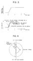
- Fig. 3 shows a response of suction air amount measurement value when an opening degree of the throttle valve is changed stepwise, a response when the above response is advanced by a desired time t0, and a response when the response of the measurement value is advanced by the time t0 by the prediction process.
- the correction unit compensates it.
- the differences between future values of the measurement data predicted by the prediction process and real future values of the measurement data are stored in the map for the respective acceleration/deceleration levels, and the measurement value produced by the prediction process is corrected by looking up the map so that the prediction precision in the early stage of the acceleration/deceleration is assured.
- the data of the map of Fig. 2 is calculated in the following manner.
- the throttle opening degree is changed at the acceleration level i from the steady operation state of the engine in which the throttle opening degree is maintained at a constant level, and an engine status amount which is a subjet of current prediction is measured.
- the response of the measurement value is represented by S1(t)
- a response when the above response is advanced by the time t0 is represented by S1(t + t0).
- a response when the response S1(t) is advanced by the prediction process is represented by S2(t).
- Data D(t) of the acceleration level i of the map is calculated by the following formula: where
- the fuel supply amount in the next step is determined based on the detection value of the current air amount in the existing system, there is approximately one stroke of delay in the detection of the air amount and hence it is difficult to precisely control the air-to-fuel ratio.
- the detection value of the air amount to be used for the determination of the fuel supply amount is advanced by a time difference between the time at which the air amount is to be inherently detected, that is, the time at which the exact cylinder inlet air amount of the next step is to be detected and a time at which the air amount to be used for the determination of the fuel supply amount is to be detected.
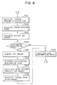
- the above time amount may be considered to be essentially within the range of the crank angle defined by the following formula, assuming that the fuel injection timing is ⁇ i crank angle before a top dead center and a suction stroke is from ⁇ s crank angle before the top dead center to ⁇ e crank angle after the top dead center, as shown in Fig. 4.
- ⁇ i - ⁇ s ⁇ ⁇ d ⁇ ⁇ i + ⁇ e 21)
- the above time difference T d (sec) is within the following range where N (rpm) is the engine rotating speed.
- the air amount at the time which is ahead by the time given by the formula (22) is predicted by the above prediction method and the fuel is controlled based on the predicted value.
- the delay in the detection of the air amount in the transient state is theoretically compensated and high precision control of the air-to-fuel ratio is attained.
- FIG. 5 shows an overall configuration of a fuel injection control apparatus which uses a speed density system (D jetronic system).
- a control unit 50 comprises a CPU 51, a ROM 52, a RAM 53, an I/O LSI 54, a timer 55 and a bus which electrically connects those elements. Signals from a throttle angle sensor 57, an internal pressure sensor 58, a coolant temperature sensor 59, a crank angle sensor 511 and an oxygen sensor 512 are supplied to the I/O LSI 54.
- the I/O LSI 53 sends a signal to a fuel injector 513.
- the I/O LSI 54 has an A/D converter and a D/A converter.
- the timer 55 issues an interruption request to the CPU 51 at a constant time interval, and the CPU 51 responds thereto to execute the control program stored in the ROM 52.
- the output of the pressure sensor is A/D-converted in a step 501 to determine an internal pressure of a suction pipe.
- a step 502 an engine rotating speed is determined based on a signal from the crank angle sensor 511.
- the data table stored in the RAM 53 is retrieved by using the engine rotating speed and the internal pressure of the suction pipe as parameters, to determine the engine suction air amount, which is stored into a predetermined address of the RAM 53.
- step 504 whether the vehicle is in the acceleration/deceleration state is determined by the method described above. If it is in the acceleration/deceleration state, the process proceeds to a step 505, and if not, the process proceeds to a step 509.
- a step 505 the future value of the suction air amount which is ahead of the time of the formula (22) is predicted by the prediction process by the advancing filter, that is, by utilizing the formulas (10), (11), (12), (13) and (14) based on the suction air amount determined in the step 503, and the time-sequential data of the suction air amounts determined in the past interruptions and stored in the RAM 53.
- ⁇ t represents the interruption period (10 msec.).
- the acceleration/deceleration level is determined based on the displacement of the throttle opening degree in the manner described above.
- a step 507 the data table stored in the RAM 53 is looked up based on the acceleration/deceleration level and the elapsed time from the start of the acceleration/deceleration, and the looked-up value is multiplied by the time to which the suction air amount is to be advanced as shown in the formula (22) to calculate an air amount ⁇ Qa which is under or over when the prediction process by the advancing filter is conducted.
- a step 508 the air amount ⁇ Qa which is under or over when the prediction process is conducted is added to the air amount Q ⁇ a' predicted by the advancing filter to calculate a true future value Q ⁇ a of the suction air amount which is ahead by the time given by the formula (22).
- a fuel injection pulse width T i corresponding to the fuel injection amount is calculated by the formula (24) based on the air amount Qa calculated in the step 503.
- the fuel injection pulse width T i is calculated by the formula (25) based on the future value Q ⁇ a of the air amount determined by the step 508.
- the suction air amount is predicted to determine the future value thereof.
- the time-serial data of the internal pressure of the suction pipe and the rotating speed may be stored, the future values of the internal pressure and the rotating speed may be determined from the time-serial data, and the data table may be looked up by the future values to determine the suction air amount so that the future value of the air amount is determined.
- the prediction may be done by the prediction unit described above or the prediction method shown in Fig. 1.
- the application to the engine of the speed density type has been described.
- the present invention is also applicable to the prediction of the air amount of a throttle speed type or a mass flow type (L jetronic system) which directly detects an electrical amount.
- the throttle speed type which infers the suction air amount based mainly on the throttle opening degree and the rotating speed
- the future value is not predicted based on the time-serial data of the inferred values of the air amount, but the future values of the throttle opening degree and the rotating speed are predicted and the suction air amount is inferred based on the predicted values to predict the future value of the air amount.
- the suction air amount may be inferred based on the future value of the throttle opening degree and the present value of the rotating speed.
- the prediction may be done by the prediction unit described above or the prediction method shown in Fig. 1.
- the pulse width T i of the synchronous injection may be calculated by the following formula based on the air amount predicted by the advancing filter, and the pulse width T i ' of the asynchronous injection may be calculated by the following formula based on the under prediction ⁇ Qa of the air amount calculated for each acceleration/deceleration level.
- the future value of the air amount for compensating the delay in the detection of the air amount is predicted.
- the delay in the detection of the air amount may also be compensated by applying the prediction method described above to the fundamental injection pulse width T p which is calculated by the control unit at the interval of 10 msec.
- the fundamental injection pulse width which is ahead of the time defined by the formula (22) is predicted based on the past data in the prediction method shown in Fig. 1, and the fuel injection pulse width T i is calculated by the following formula based on the predicted value T ⁇ p .
- T i k ⁇ T ⁇ p + T s (29) Since the delay in the detection of the air amount is compensated in this manner, the fundamental injection pulse width at the time at which the exact suction air amount in the next stroke is to be detected can be predicted so that the high precision control of the air-to-fuel ratio is attained.
Landscapes
- Engineering & Computer Science (AREA)
- Chemical & Material Sciences (AREA)
- Combustion & Propulsion (AREA)
- Mechanical Engineering (AREA)
- General Engineering & Computer Science (AREA)
- Computer Hardware Design (AREA)
- Microelectronics & Electronic Packaging (AREA)
- Combined Controls Of Internal Combustion Engines (AREA)
- Electrical Control Of Air Or Fuel Supplied To Internal-Combustion Engine (AREA)
Claims (9)
- Procédé de commande d'un moteur à combustion interne avec injection de carburant, comprenant les opérations suivantes :(A) déterminer (étape 503) la quantité d'air admis Qa avec les paramètres pression d'admission et vitesse de rotation,(B) prédire (étape 505) une valeur future pour la quantité d'air admis Q̂a' par un filtre à avance numérique à l'aide des quantités réelle et précédente d'air admis mémorisées dans une RAM (53),(C) déterminer (étape 506) un niveau accélération/décélération dans une unité (12) de détermination du niveau accélération/décélération en fonction du déplacement Δϑth d'un papillon de gaz en un temps prédéterminé,(D) déterminer une quantité correctrice ΔQa (étape 507) en fonction du niveau accélération/décélération, du temps écoulé depuis le début de l'opération accélération/décélération, et du temps auquel la quantité d'air admis doit être avancée,(E) corriger (étape 508) la valeur future de la quantité d'air admis Q̂a' dans une unité de correction (13) en ajoutant la quantité correctrice ΔQa afin d'obtenir une valeur future corrigée pour la quantité d'air admis Q̂a, et(F) commander (étape 509) l'injection de carburant en fonction de la valeur future corrigée de la quantité d'air admis Q̂a.
- Procédé selon la revendication 1, caractérisé en ce qu'on détermine la quantité réelle d'air admis Qa à partir d'une table de données mémorisée à une adresse prédéterminée de la RAM (35) (étape 503).
- Procédé selon la revendication 1 ou 2, caractérisé en ce que :
on effectue la correction de la quantité prédite d'air admis Q̂a' en lisant une table de données avec quantités correctrices unifiées D(t) mémorisée à une adresse prédéterminée d'une RAM (35), le niveau accélération/décélération et le temps écoulé depuis le début de l'opération accélération/décélération étant pris comme paramètres, et
on multiplie les quantité correctrices unifiées D(t) par le temps auquel la quantité d'air admis doit être avancée afin d'obtenir les quantités correctrices ΔQa (étapes 507, 508). - Procédé selon les revendications 1-3, caractérisé en ce qu'on effectue la correction de la quantité prédite d'air admis Q̂a' afin de compenser l'erreur des quantités prédites d'air admis Q̂a' obtenues lors de l'étape précédente d'accélération/décélération.
- Procédé de commande d'un moteur à combustion interne avec injection de carburant, comprenant les opérations suivantes :(A) prédire une valeur future de la pression dans le collecteur par un filtre à avance numérique effectuant une dérivation du nème ordre à l'aide des pressions réelle et précédente dans le collecteur mémorisées dans une RAM (35),(B) prédire une valeur future pour la vitesse du moteur par un filtre à avance numérique effectuant une dérivation du nème ordre à l'aide des vitesses de moteur réelle et précédente mémorisées dans la RAM (35),(C) déterminer (étape 506) un niveau accélération/décélération en fonction du déplacement Δϑth d'un papillon de gaz en un temps prédéterminé,(D) déterminer une quantité correctrice pour la valeur future de la pression dans le collecteur en fonction du niveau accélération/décélération, du temps écoulé depuis le début de l'opération accélération/décélération et du temps auquel la pression dans le collecteur doit être avancée,(E) déterminer une quantité correctrice pour la valeur future de la vitesse du moteur en fonction du niveau accélération/décélération, du temps écoulé depuis le début de l'opération accélération/décélération et du temps auquel la vitesse du moteur doit être avancée,(F) corriger la valeur future de la pression dans le collecteur en ajoutant la quantité correctrice pour la valeur future de la pression dans le collecteur afin d'obtenir une valeur future corrigée de la pression dans le collecteur,(G) corriger la valeur future de la vitesse du moteur en ajoutant la quantité correctrice pour la valeur future de la vitesse du moteur afin d'obtenir une valeur future corrigée de la vitesse du moteur,(H) déterminer la valeur future de la quantité d'air admis Q̂a avec les paramètres valeur future corrigée de la pression dans le collecteur et valeur future corrigée de la vitesse du moteur, et(I) commander l'injection de carburant en fonction de la valeur future de la quantité d'air admis Q̂a.
- Procédé selon la revendication 5, caractérisé en ce que :
on effectue la correction de la pression prédite dans le collecteur en lisant une première table de données avec des premières quantités correctrices unifiées mémorisée à une adresse prédéterminée dans la RAM (35), les paramètres étant le niveau accélération/décélération et le temps écoulé depuis le début de l'opération accélération/décélération,
on multiplie les premières quantités correctrices unifiées par le temps auquel la pression dans le collecteur doit être avancée afin d'obtenir les quantités correctrices pour la valeur future de la pression dans le collecteur,
on effectue la correction de la vitesse du moteur prédite en lisant une deuxième table de données avec des deuxièmes valeurs correctrices unifiées mémorisée à une autre adresse prédéterminée de la RAM (35), les paramètres étant le niveau accélération/décélération et le temps écoulé depuis le début de l'opération accélération/décélération, et
on multiplie les deuxièmes quantités correctrices unifiées par le temps auquel la vitesse du moteur doit être avancée afin d'obtenir les quantités correctrices pour la valeur future de la vitesse du moteur. - Procédé de commande d'un moteur à combustion interne avec injection de carburant, comprenant les opérations suivantes :(A) prédire une valeur future pour l'angle du papillon par un filtre à avance numérique effectuant une dérivation du nème ordre à l'aide des angles de papillon réel et précédent mémorisés dans une RAM (35),(B) prédire une valeur future pour la vitesse du moteur par un filtre à avance numérique effectuant une dérivation du nème ordre à l'aide des vitesses de moteur réelle et précédente mémorisées dans la RAM (35),(C) déterminer (étape 506) un niveau accélération/décélération en fonction du déplacement Δϑth d'un papillon des gaz en un temps prédéterminé,(D) déterminer une quantité correctrice pour la valeur future de l'angle du papillon en fonction du niveau accélération/décélération, du temps écoulé depuis le début de l'opération accélération/décélération et du temps auquel l'angle du papillon doit être avancé,(E) déterminer une quantité correctrice pour la valeur future de la vitesse du moteur en fonction du niveau accélération/décélération, du temps écoulé depuis le début de l'opération accélération/décélération et du temps auquel la vitesse du moteur doit être avancée,(F) corriger la valeur future de l'angle du papillon en ajoutant la quantité correctrice de la valeur future de l'angle de papillon afin d'obtenir une valeur future corrigée de l'angle du papillon,(G) corriger la valeur future de la vitesse du moteur en ajoutant la quantité correctrice de la valeur future de la vitesse du moteur afin d'obtenir une valeur future corrigée de la vitesse du moteur,(H) déterminer la valeur future de la quantité d'air admis, les paramètres étant la valeur future corrigée de l'angle du papillon et la valeur future corrigée de la vitesse du moteur, et(I) commander l'injection de carburant en fonction de la valeur future de la quantité d'air admis Q̂a.
- Procédé selon la revendication 7, caractérisé en ce que :
on effectue la correction de l'angle de papillon prédit en lisant une première table de données avec des quantités correctrices unifiées D(t) mémorisée à une adresse prédéterminée dans une RAM (35), les paramètres étant le niveau accélération/décélération et le temps écoulé depuis le début de l'opération accélération/décélération,
on multiplie les premières quantités correctrices unifiées D(t) par le temps auquel l'angle du papillon doit être avancé afin d'obtenir les quantités correctrices de la valeur future de l'angle du papillon,
on effectue la correction de la vitesse de moteur prédite en lisant une deuxième table de données avec des deuxièmes valeurs correctrices unifiées mémorisée en une autre adresse prédéterminée de la RAM (35), les paramètres étant le niveau accélération/décélération et le temps écoulé depuis le début de l'opération accélération/décélération, et
on multiplie les deuxièmes quantités correctrices unifiées par le temps auquel la vitesse du moteur doit être avancée afin d'obtenir les quantités correctrices de la valeur future de la vitesse du moteur. - Procédé selon les revendications 1-8, caractérisé en ce qu'un positionnement temporel d'injection de carburant est de ϑi degrés avant le point mort haut, la course d'aspiration va de ϑs avant le point mort haut à ϑe après le point mort haut, et le temps Td auquel l'air admis, la pression dans le collecteur ou la vitesse du moteur doivent être avancés est compris dans les limites de :

Applications Claiming Priority (4)
| Application Number | Priority Date | Filing Date | Title |
|---|---|---|---|
| JP261494/88 | 1988-10-19 | ||
| JP26149488A JP2753278B2 (ja) | 1988-10-19 | 1988-10-19 | エンジンの制御装置 |
| JP30781688A JPH02155072A (ja) | 1988-12-07 | 1988-12-07 | テーブル検索方式 |
| JP307816/88 | 1988-12-07 |
Publications (3)
| Publication Number | Publication Date |
|---|---|
| EP0365003A2 EP0365003A2 (fr) | 1990-04-25 |
| EP0365003A3 EP0365003A3 (en) | 1990-09-19 |
| EP0365003B1 true EP0365003B1 (fr) | 1994-01-19 |
Family
ID=26545107
Family Applications (1)
| Application Number | Title | Priority Date | Filing Date |
|---|---|---|---|
| EP89119416A Expired - Lifetime EP0365003B1 (fr) | 1988-10-19 | 1989-10-19 | Méthode de commande d'injection de carburant |
Country Status (4)
| Country | Link |
|---|---|
| US (1) | US5274559A (fr) |
| EP (1) | EP0365003B1 (fr) |
| KR (1) | KR900006657A (fr) |
| DE (1) | DE68912501T2 (fr) |
Families Citing this family (19)
| Publication number | Priority date | Publication date | Assignee | Title |
|---|---|---|---|---|
| FR2672087A1 (fr) * | 1991-01-29 | 1992-07-31 | Siements Automotive Sa | Procede et dispositif d'evaluation du debit d'air admis dans un moteur a combustion interne, en regime transitoire. |
| US5497329A (en) * | 1992-09-23 | 1996-03-05 | General Motors Corporation | Prediction method for engine mass air flow per cylinder |
| US5609136A (en) * | 1994-06-28 | 1997-03-11 | Cummins Engine Company, Inc. | Model predictive control for HPI closed-loop fuel pressure control system |
| EP0928369B1 (fr) * | 1996-08-23 | 2006-05-10 | Cummins Inc. | Moteur a allumage par compression d'une charge premelangee avec regulation optimale de la combustion |
| US6230683B1 (en) | 1997-08-22 | 2001-05-15 | Cummins Engine Company, Inc. | Premixed charge compression ignition engine with optimal combustion control |
| WO1999042718A1 (fr) | 1998-02-23 | 1999-08-26 | Cummins Engine Company, Inc. | Moteur a allumage par compression d'une charge prealablement melangee, et a reglage optimal de la combustion |
| US6170475B1 (en) * | 1999-03-01 | 2001-01-09 | Ford Global Technologies, Inc. | Method and system for determining cylinder air charge for future engine events |
| US6155242A (en) * | 1999-04-26 | 2000-12-05 | Ford Global Technologies, Inc. | Air/fuel ratio control system and method |
| US6460409B1 (en) * | 2000-05-13 | 2002-10-08 | Ford Global Technologies, Inc. | Feed-forward observer-based control for estimating cylinder air charge |
| JP2002201998A (ja) * | 2000-11-06 | 2002-07-19 | Denso Corp | 内燃機関の制御装置 |
| US6470675B1 (en) * | 2001-06-20 | 2002-10-29 | Ford Global Technologies, Inc. | System and method controlling engine based on predicated engine operating conditions |
| US6993899B2 (en) * | 2001-06-20 | 2006-02-07 | Ford Global Technologies, Llc | System and method for controlling catalyst storage capacity |
| US6453661B1 (en) * | 2001-06-20 | 2002-09-24 | Ford Global Technologies, Inc. | System and method for determining target oxygen storage in an automotive catalyst |
| US6598468B2 (en) | 2001-07-11 | 2003-07-29 | Cummins Inc. | Apparatus and methods for determining start of combustion for an internal combustion engine |
| KR100440163B1 (ko) * | 2002-06-29 | 2004-07-12 | 현대자동차주식회사 | 실린더 흡입 공기량 산출방법 및 시스템 그리고 이를이용한 엔진 연료 제어 방법 및 시스템 |
| EP1787019A1 (fr) | 2004-08-27 | 2007-05-23 | Optimum Power Technology, L.P. | Gestion predictive de la combustion moteur |
| US8868252B2 (en) * | 2007-11-03 | 2014-10-21 | GM Global Technology Operations LLC | Control architecture and method for two-dimensional optimization of input speed and input power including search windowing |
| US8433486B2 (en) | 2007-11-07 | 2013-04-30 | GM Global Technology Operations LLC | Method and apparatus to determine a preferred operating point for an engine of a powertrain system using an iterative search |
| US8095299B2 (en) * | 2009-02-13 | 2012-01-10 | Ford Global Technologies, Llc | Method for starting a vehicle engine |
Citations (2)
| Publication number | Priority date | Publication date | Assignee | Title |
|---|---|---|---|---|
| DE2906782A1 (de) * | 1979-02-22 | 1980-09-04 | Bosch Gmbh Robert | Einrichtung zum daempfen von ruckelschwingungen bei einer brennkraftmaschine |
| EP0332119A2 (fr) * | 1988-03-09 | 1989-09-13 | Hitachi, Ltd. | Méthode de commande de moteur de type électronique |
Family Cites Families (13)
| Publication number | Priority date | Publication date | Assignee | Title |
|---|---|---|---|---|
| US3631520A (en) * | 1968-08-19 | 1971-12-28 | Bell Telephone Labor Inc | Predictive coding of speech signals |
| US3619360A (en) * | 1968-12-17 | 1971-11-09 | Beloit Corp | Basis weight control system for a papermaking machine |
| US4424568A (en) * | 1980-01-31 | 1984-01-03 | Hitachi, Ltd. | Method of controlling internal combustion engine |
| JPS58172446A (ja) * | 1982-04-02 | 1983-10-11 | Honda Motor Co Ltd | 内燃機関の作動状態制御装置 |
| US4548185A (en) * | 1984-09-10 | 1985-10-22 | General Motors Corporation | Engine control method and apparatus |
| DE3636810A1 (de) * | 1985-10-29 | 1987-04-30 | Nissan Motor | Kraftstoffeinspritzregelsystem fuer eine brennkraftmaschine |
| JPH081142B2 (ja) * | 1986-04-28 | 1996-01-10 | マツダ株式会社 | エンジンの空燃比制御装置 |
| JPH0730728B2 (ja) * | 1987-05-30 | 1995-04-10 | マツダ株式会社 | エンジンのアイドル回転数制御装置 |
| JP2569586B2 (ja) * | 1987-08-21 | 1997-01-08 | トヨタ自動車株式会社 | 内燃機関の電子制御装置 |
| JPH01216053A (ja) * | 1988-02-24 | 1989-08-30 | Fuji Heavy Ind Ltd | エンジンの燃料噴射制御装置 |
| US4974563A (en) * | 1988-05-23 | 1990-12-04 | Toyota Jidosha Kabushiki Kaisha | Apparatus for estimating intake air amount |
| US5003950A (en) * | 1988-06-15 | 1991-04-02 | Toyota Jidosha Kabushiki Kaisha | Apparatus for control and intake air amount prediction in an internal combustion engine |
| JPH02104930A (ja) * | 1988-10-13 | 1990-04-17 | Fuji Heavy Ind Ltd | 内燃機関の燃料噴射制御装置 |
-
1989
- 1989-10-16 US US07/421,783 patent/US5274559A/en not_active Expired - Lifetime
- 1989-10-18 KR KR1019890014986A patent/KR900006657A/ko not_active Ceased
- 1989-10-19 EP EP89119416A patent/EP0365003B1/fr not_active Expired - Lifetime
- 1989-10-19 DE DE68912501T patent/DE68912501T2/de not_active Expired - Fee Related
Patent Citations (2)
| Publication number | Priority date | Publication date | Assignee | Title |
|---|---|---|---|---|
| DE2906782A1 (de) * | 1979-02-22 | 1980-09-04 | Bosch Gmbh Robert | Einrichtung zum daempfen von ruckelschwingungen bei einer brennkraftmaschine |
| EP0332119A2 (fr) * | 1988-03-09 | 1989-09-13 | Hitachi, Ltd. | Méthode de commande de moteur de type électronique |
Also Published As
| Publication number | Publication date |
|---|---|
| EP0365003A2 (fr) | 1990-04-25 |
| EP0365003A3 (en) | 1990-09-19 |
| DE68912501T2 (de) | 1994-06-30 |
| US5274559A (en) | 1993-12-28 |
| DE68912501D1 (de) | 1994-03-03 |
| KR900006657A (ko) | 1990-05-08 |
Similar Documents
| Publication | Publication Date | Title |
|---|---|---|
| EP0365003B1 (fr) | Méthode de commande d'injection de carburant | |
| US5282449A (en) | Method and system for engine control | |
| JP2556964B2 (ja) | 内燃機関用アイドル運転制御装置 | |
| EP0461480B1 (fr) | Méthode et dispositif de commande de l'injection de carburant dans un moteur à combustion interne | |
| EP0924421B1 (fr) | Dispositif pour régler l'injection de carburant pour moteur à combustion interne | |
| EP0401847B1 (fr) | Procédé et appareil pour commander un moteur sur banc d'essai | |
| JP2830265B2 (ja) | 気筒流入空気量算出装置 | |
| EP0345814B1 (fr) | Appareil de commande électrique pour automobile et méthode de compensation du retard de mesure des données | |
| EP0387100B1 (fr) | Procédé et dispositif pour la commande de l'instant d'allumage dans un moteur à combustion interne | |
| EP0546579B1 (fr) | Système d'alimentation en carburant par injection électronique | |
| JP2562577B2 (ja) | 内燃機関用アイドル運転制御装置 | |
| US5611315A (en) | Fuel supply amount control apparatus for internal combustion engine | |
| GB2266975A (en) | Fuel metering control | |
| US4635201A (en) | Apparatus for detecting amount of change in rotational speed of internal combustion engine | |
| EP0378814B1 (fr) | Méthode de commande du rapport air-carburant | |
| US4548180A (en) | Method for controlling the operating condition of an internal combustion engine | |
| EP0157340B1 (fr) | Méthode de commande de l'alimentation en carburant d'un moteur à combustion interne | |
| US6985806B2 (en) | Method for determining an estimated value of a mass flow in the intake channel of an internal combustion engine | |
| EP0332119B1 (fr) | Méthode de commande de moteur de type électronique | |
| EP0156356B1 (fr) | Méthode de contrôle de l'alimentation en carburant d'un moteur à combustion interne | |
| JP2753278B2 (ja) | エンジンの制御装置 | |
| JP3131333B2 (ja) | エンジンの電子制御燃料噴射装置 | |
| EP0332962B1 (fr) | Méthode et appareil de commande de moteur | |
| US6370469B1 (en) | Cruise control method | |
| JPH0777098A (ja) | 内燃機関の燃料噴射時期制御装置 |
Legal Events
| Date | Code | Title | Description |
|---|---|---|---|
| PUAI | Public reference made under article 153(3) epc to a published international application that has entered the european phase |
Free format text: ORIGINAL CODE: 0009012 |
|
| AK | Designated contracting states |
Kind code of ref document: A2 Designated state(s): DE FR GB |
|
| PUAL | Search report despatched |
Free format text: ORIGINAL CODE: 0009013 |
|
| AK | Designated contracting states |
Kind code of ref document: A3 Designated state(s): DE FR GB |
|
| 17P | Request for examination filed |
Effective date: 19900921 |
|
| 17Q | First examination report despatched |
Effective date: 19910122 |
|
| RBV | Designated contracting states (corrected) |
Designated state(s): DE GB |
|
| GRAA | (expected) grant |
Free format text: ORIGINAL CODE: 0009210 |
|
| AK | Designated contracting states |
Kind code of ref document: B1 Designated state(s): DE GB |
|
| REF | Corresponds to: |
Ref document number: 68912501 Country of ref document: DE Date of ref document: 19940303 |
|
| PLBE | No opposition filed within time limit |
Free format text: ORIGINAL CODE: 0009261 |
|
| STAA | Information on the status of an ep patent application or granted ep patent |
Free format text: STATUS: NO OPPOSITION FILED WITHIN TIME LIMIT |
|
| 26N | No opposition filed | ||
| REG | Reference to a national code |
Ref country code: GB Ref legal event code: IF02 |
|
| PGFP | Annual fee paid to national office [announced via postgrant information from national office to epo] |
Ref country code: GB Payment date: 20050926 Year of fee payment: 17 |
|
| PGFP | Annual fee paid to national office [announced via postgrant information from national office to epo] |
Ref country code: DE Payment date: 20051202 Year of fee payment: 17 |
|
| PG25 | Lapsed in a contracting state [announced via postgrant information from national office to epo] |
Ref country code: DE Free format text: LAPSE BECAUSE OF NON-PAYMENT OF DUE FEES Effective date: 20070501 |
|
| GBPC | Gb: european patent ceased through non-payment of renewal fee |
Effective date: 20061019 |
|
| PG25 | Lapsed in a contracting state [announced via postgrant information from national office to epo] |
Ref country code: GB Free format text: LAPSE BECAUSE OF NON-PAYMENT OF DUE FEES Effective date: 20061019 |