EP0365130B1 - Tuyère d'injection de combustible - Google Patents
Tuyère d'injection de combustible Download PDFInfo
- Publication number
- EP0365130B1 EP0365130B1 EP89309046A EP89309046A EP0365130B1 EP 0365130 B1 EP0365130 B1 EP 0365130B1 EP 89309046 A EP89309046 A EP 89309046A EP 89309046 A EP89309046 A EP 89309046A EP 0365130 B1 EP0365130 B1 EP 0365130B1
- Authority
- EP
- European Patent Office
- Prior art keywords
- fuel
- stem
- actuating piston
- poppet valve
- chamber
- Prior art date
- Legal status (The legal status is an assumption and is not a legal conclusion. Google has not performed a legal analysis and makes no representation as to the accuracy of the status listed.)
- Expired - Lifetime
Links
- 239000000446 fuel Substances 0.000 title claims description 70
- 238000002347 injection Methods 0.000 title claims description 51
- 239000007924 injection Substances 0.000 title claims description 51
- MWUXSHHQAYIFBG-UHFFFAOYSA-N Nitric oxide Chemical compound O=[N] MWUXSHHQAYIFBG-UHFFFAOYSA-N 0.000 description 15
- 238000002485 combustion reaction Methods 0.000 description 8
- 239000004215 Carbon black (E152) Substances 0.000 description 5
- 229930195733 hydrocarbon Natural products 0.000 description 5
- 150000002430 hydrocarbons Chemical class 0.000 description 5
- 230000002708 enhancing effect Effects 0.000 description 2
- 238000010276 construction Methods 0.000 description 1
- 238000003780 insertion Methods 0.000 description 1
- 230000037431 insertion Effects 0.000 description 1
- 239000000203 mixture Substances 0.000 description 1
- 238000013022 venting Methods 0.000 description 1
Images

Classifications
-
- F—MECHANICAL ENGINEERING; LIGHTING; HEATING; WEAPONS; BLASTING
- F02—COMBUSTION ENGINES; HOT-GAS OR COMBUSTION-PRODUCT ENGINE PLANTS
- F02M—SUPPLYING COMBUSTION ENGINES IN GENERAL WITH COMBUSTIBLE MIXTURES OR CONSTITUENTS THEREOF
- F02M61/00—Fuel-injectors not provided for in groups F02M39/00 - F02M57/00 or F02M67/00
- F02M61/16—Details not provided for in, or of interest apart from, the apparatus of groups F02M61/02 - F02M61/14
- F02M61/20—Closing valves mechanically, e.g. arrangements of springs or weights or permanent magnets; Damping of valve lift
-
- F—MECHANICAL ENGINEERING; LIGHTING; HEATING; WEAPONS; BLASTING
- F02—COMBUSTION ENGINES; HOT-GAS OR COMBUSTION-PRODUCT ENGINE PLANTS
- F02M—SUPPLYING COMBUSTION ENGINES IN GENERAL WITH COMBUSTIBLE MIXTURES OR CONSTITUENTS THEREOF
- F02M61/00—Fuel-injectors not provided for in groups F02M39/00 - F02M57/00 or F02M67/00
- F02M61/04—Fuel-injectors not provided for in groups F02M39/00 - F02M57/00 or F02M67/00 having valves, e.g. having a plurality of valves in series
- F02M61/042—The valves being provided with fuel passages
- F02M61/045—The valves being provided with fuel discharge orifices
-
- F—MECHANICAL ENGINEERING; LIGHTING; HEATING; WEAPONS; BLASTING
- F02—COMBUSTION ENGINES; HOT-GAS OR COMBUSTION-PRODUCT ENGINE PLANTS
- F02M—SUPPLYING COMBUSTION ENGINES IN GENERAL WITH COMBUSTIBLE MIXTURES OR CONSTITUENTS THEREOF
- F02M61/00—Fuel-injectors not provided for in groups F02M39/00 - F02M57/00 or F02M67/00
- F02M61/04—Fuel-injectors not provided for in groups F02M39/00 - F02M57/00 or F02M67/00 having valves, e.g. having a plurality of valves in series
- F02M61/08—Fuel-injectors not provided for in groups F02M39/00 - F02M57/00 or F02M67/00 having valves, e.g. having a plurality of valves in series the valves opening in direction of fuel flow
-
- F—MECHANICAL ENGINEERING; LIGHTING; HEATING; WEAPONS; BLASTING
- F02—COMBUSTION ENGINES; HOT-GAS OR COMBUSTION-PRODUCT ENGINE PLANTS
- F02B—INTERNAL-COMBUSTION PISTON ENGINES; COMBUSTION ENGINES IN GENERAL
- F02B2275/00—Other engines, components or details, not provided for in other groups of this subclass
- F02B2275/14—Direct injection into combustion chamber
-
- Y—GENERAL TAGGING OF NEW TECHNOLOGICAL DEVELOPMENTS; GENERAL TAGGING OF CROSS-SECTIONAL TECHNOLOGIES SPANNING OVER SEVERAL SECTIONS OF THE IPC; TECHNICAL SUBJECTS COVERED BY FORMER USPC CROSS-REFERENCE ART COLLECTIONS [XRACs] AND DIGESTS
- Y02—TECHNOLOGIES OR APPLICATIONS FOR MITIGATION OR ADAPTATION AGAINST CLIMATE CHANGE
- Y02T—CLIMATE CHANGE MITIGATION TECHNOLOGIES RELATED TO TRANSPORTATION
- Y02T10/00—Road transport of goods or passengers
- Y02T10/10—Internal combustion engine [ICE] based vehicles
- Y02T10/12—Improving ICE efficiencies
Definitions
- This invention relates to a fuel injection nozzle for delivering fuel to the combustion chamber of an internal combustion engine.
- a pump supplies a measured amount of fuel to a fuel injection nozzle for delivery directly into the engine combustion chamber.
- US-A-4693424 describes a fuel injection nozzle having an outwardly opening poppet valve that controls delivery of fuel to the engine combustion chamber. That fuel injection nozzle allows the engine to operate with lower noise, hydrocarbon and nitrogen oxide emissions than engines with other nozzles.
- FR-A-2289756 discloses a fuel injection valve assembly in which a poppet valve with upper and lower sets of orifices discharge fuel sequentially to improve dosage mixture. During light load operation, for example during idling, only the lower set of orifices might be used.
- US-A-4750675 describes an improved fuel injection nozzle also having an outwardly opening poppet valve that controls delivery of fuel to the engine combustion chamber. That improved fuel injection nozzle includes a piston that dampens opening movement of the poppet valve, thereby reducing the initial rate of injection and thus enhancing the ability of the engine to operate with low noise, hydrocarbon and nitrogen oxide emissions.
- This invention provides a further improved fuel injection nozzle also having an outwardly opening poppet valve that controls the delivery of fuel to the engine combustion chamber.
- a fuel injection nozzle in accordance with the present invention is characterised over US-A-4750675 by the features specified in the characterising portion of claim 1.
- an actuating piston increases the difference between the injection pressure required to initiate opening of the poppet valve and the injection pressure required to fully open the poppet valve.
- the actuating piston effectively limits opening of the poppet valve during light load engine operation, thereby reducing the rate of injection during light load engine operation and thus enhancing the ability of the engine to operate with low noise, hydrocarbon and nitrogen oxide emissions.
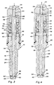
- a nozzle 10 has a body 12 adapted to be received in an engine cylinder head, and a holder 14 having a fitting 16 that receives fuel from an injection pump. Body 12 and holder 14 are threaded together at 18, and a gasket 20 seals the threaded connection.
- a poppet valve 22 is received in a bore 24 of body 12.
- Poppet valve 22 has a head 26 that engages a lower end 28 of body 12, and a stem 30 that extends into a chamber 32 formed between body 12 and holder 14.
- a spring 34 is compressed between a spring retainer 36 secured around the upper end of stem 30 and a stop member 38 that rests against the top 40 of body 12.
- Holder 14 has a fuel inlet passage 42 that opens into a piston bore 44.
- An actuating piston 46 is lapped fit in piston bore 44.
- the lower end 48 of actuating piston 46 is tapered or recessed to a face 50 that seals against the top 52 of stem 30.
- the area of the upper face 53 of actuating piston 46 and the characteristics of spring 34 are chosen so that, in response to the lower injection pressures of light load engine operation, poppet valve 22 is displaced only far enough to expose the lower set of orifices 58 below the lower end 28 of body 12.
- poppet valve 22 In response to the higher injection pressures of heavy load engine operation, poppet valve 22 is displaced until a shoulder 64 on stem 30 engages stop member 38. At that time, both sets of orifices 58 and 60 are exposed below the lower end 28 of body 12 to allow delivery of the fuel required for heavy load engine operation.
- An opening 66 through stop member 38 is eccentric to the axis of fuel injection nozzle 10, thereby allowing stop member 38 to be assembled around stem 30 and then, upon insertion into holder 14, to slide laterally under shoulder 64 to act as a stop for poppet valve 22.
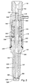
- a fuel injection nozzle 110 has a body 112 adapted to be received in an engine cylinder head, and a holder 114 having a fitting 116 that receives fuel from an injection pump. Body 112 and holder 114 are threaded together at 118, and a gasket 120 seals the threaded connection.
- a poppet valve 122 is received in a bore 124 of body 112.
- Poppet valve 122 has a head 126 that engages a lower end 128 of body 112, and a stem 130 that extends into a chamber 132 formed between body 112 and holder 114.
- a spring 134 is compressed between a spring retainer 136 secured around an upper end of stem 130 and a stop member 138 that rests against the top 140 of body 112.
- Holder 114 has a fuel inlet passage 142 that opens into a piston bore 144.
- An actuating piston 146 formed as an extension of stem 130 is received in piston bore 144.
- the area of the upper face 153 of actuating piston 146 and the characteristics of spring 134 are chosen so that, in response to the lower injection pressures of light load engine operation, poppet valve 122 is displaced only far enough to expose the lower set of orifices 158 below the lower end 128 of body 112.
- poppet valve 122 In response to the higher injection pressures of heavy load engine operation, poppet valve 122 is displaced until a shoulder 164 on stem 130 engages stop member 138. At that time, both sets of orifices 158 and 160 are exposed below the lower end 128 of body 112 to allow delivery of the fuel required for heavy load engine operation.
Landscapes
- Engineering & Computer Science (AREA)
- Chemical & Material Sciences (AREA)
- Combustion & Propulsion (AREA)
- Mechanical Engineering (AREA)
- General Engineering & Computer Science (AREA)
- Fuel-Injection Apparatus (AREA)
Claims (3)
- Injecteur (10, 110) de carburant ayant un corps (12, 112) qui a un alésage axial (24, 124), une soupape à tige (22, 122) ayant une tige (30, 130) logée dans l'alésage et une tête (26, 126) destinée à venir au contact d'une extrémité (28, 128) du corps, un ressort (34, 134) rappelant la tige afin qu'elle mette la tête au contact de l'extrémité du corps, et un organe de retenue (14, 114) fixé au corps, l'organe de retenue ayant un passage (42, 142) d'entrée de carburant, le passage d'entrée de carburant débouchant dans un alésage (44, 144) de piston formé dans l'organe de retenue, si bien que le carburant peut circuler dans le passage d'entrée de carburant et dans des moyens formant passage (56, 155) formés dans la tige vers un premier et un second ensemble d'orifices (58, 60, 158, 160) traversant la tige à partir des moyens formant passage afin que le carburant soit évacué par les orifices dans un espace (62) formé entre la tête et l'extrémité du corps, caractérisé en ce qu'un piston de manoeuvre (46, 146) est logé dans l'alésage de piston, le piston de manoeuvre ayant une face (53, 153) qui est exposée à la pression d'injection du carburant régnant dans le passage d'entrée du carburant, et des moyens formant passage (54, 155) de circulation du carburant du passage d'entrée de carburant vers les moyens formant passage de la tige, le piston de manoeuvre étant destiné à transférer la pression d'injection à la tige afin que la soupape à tige soit déplacée malgré la force de rappel du ressort et permette l'écoulement du carburant, en ce que la section de la face du piston de manoeuvre et les caractéristiques du ressort sont choisies afin que, en réponse à des faibles pressions d'injection lors du fonctionnement du moteur à faible charge, la soupape à tige ne se déplace que suffisamment pour permettre l'évacuation du carburant par le premier ensemble (58, 158) d'orifices, et que, en réponse à des pressions plus élevées d'injection lors du fonctionnement du moteur à forte charge, la soupape à tige se déplace suffisamment pour permettre l'évacuation du carburant par tous les orifices, si bien que le débit de carburant évacué lors du fonctionnement du moteur à faible charge est inférieur au débit de carburant évacué lors du fonctionnement du moteur à forte charge.
- Injecteur de carburant selon la revendication 1, dans lequel la tige (30) s'étend dans une chambre (32) formée entre le corps (12) et l'organe de retenue (14), le piston de manoeuvre (46) s'étend dans la chambre et a une autre face (50) destinée à coopérer de manière étanche avec une extrémité (52) de la tige, et l'aire de la face (52) du piston de manoeuvre (46) qui est exposée à la pression d'injection est supérieure à l'aire de la face (50) du piston de manoeuvre qui est destinée à coopérer de manière étanche avec l'extrémité (52) de la tige, si bien que, lorsque le ressort (34) déplace la soupape à tige (22) afin que la tête (26) soit remise au contact de l'extrémité (28) du corps, le piston de manoeuvre se soulève et s'écarte de l'extrémité (52) de la tige et évacue la pression de la chambre par les moyens formant passage (56) formés dans le piston de manoeuvre, vers le passage (42) d'entrée de carburant.
- Injecteur de carburant selon la revendication 1, dans lequel la tige (130) s'étend dans une chambre (132) formée entre le corps (112) et l'organe de retenue (114), le piston de manoeuvre (146) est un prolongement de la tige (130), et l'injecteur de carburant a un passage (168) qui débouche de la chambre (132) afin que la pression de la chambre soit évacuée lorsque le ressort (134) déplace la soupape à tige (122) afin qu'elle remette la tête (126) au contact de l'extrémité (128) du corps.
Applications Claiming Priority (2)
| Application Number | Priority Date | Filing Date | Title |
|---|---|---|---|
| US07/258,903 US4909444A (en) | 1988-10-17 | 1988-10-17 | Poppet covered orifice fuel injection nozzle |
| US258903 | 1988-10-17 |
Publications (2)
| Publication Number | Publication Date |
|---|---|
| EP0365130A1 EP0365130A1 (fr) | 1990-04-25 |
| EP0365130B1 true EP0365130B1 (fr) | 1992-10-28 |
Family
ID=22982634
Family Applications (1)
| Application Number | Title | Priority Date | Filing Date |
|---|---|---|---|
| EP89309046A Expired - Lifetime EP0365130B1 (fr) | 1988-10-17 | 1989-09-06 | Tuyère d'injection de combustible |
Country Status (4)
| Country | Link |
|---|---|
| US (1) | US4909444A (fr) |
| EP (1) | EP0365130B1 (fr) |
| JP (1) | JPH02149767A (fr) |
| DE (1) | DE68903324T2 (fr) |
Families Citing this family (19)
| Publication number | Priority date | Publication date | Assignee | Title |
|---|---|---|---|---|
| JP2521057Y2 (ja) * | 1990-07-11 | 1996-12-25 | 株式会社ゼクセル | 燃料噴射ノズル |
| US5127584A (en) * | 1991-05-06 | 1992-07-07 | General Motors Corporation | Fuel injection nozzle |
| DE4332124A1 (de) * | 1993-09-22 | 1995-03-23 | Bosch Gmbh Robert | Kraftstoffeinspritzdüse für Brennkraftmaschinen |
| DE4444363A1 (de) * | 1994-12-14 | 1996-06-20 | Bosch Gmbh Robert | Mehrstrahl-Kraftstoffeinspritzdüse |
| DE19645900A1 (de) * | 1996-11-07 | 1998-05-14 | Bosch Gmbh Robert | Kraftstoffeinspritzventil für Brennkraftmaschinen |
| GB9811649D0 (en) * | 1998-05-29 | 1998-07-29 | Lucas Ind Plc | Fuel injector |
| AUPP861299A0 (en) * | 1999-02-11 | 1999-03-04 | Casey, Alan Patrick | Direct fuel injection |
| US6260776B1 (en) * | 2000-01-12 | 2001-07-17 | Woodward Governor Company | Universal gaseous fuel injector cartridge |
| US6454189B1 (en) * | 2000-07-03 | 2002-09-24 | Caterpillar Inc. | Reverse acting nozzle valve and fuel injector using same |
| US6764028B2 (en) * | 2001-04-04 | 2004-07-20 | Synerject, Llc | Fuel injector nozzles |
| KR100444857B1 (ko) * | 2001-10-16 | 2004-08-21 | 현대자동차주식회사 | 디젤 엔진용 연료 분사 노즐 |
| DE102004033842A1 (de) * | 2004-07-13 | 2006-02-09 | Robert Bosch Gmbh | Brennstoffeinspritzventil |
| US7334741B2 (en) * | 2005-01-28 | 2008-02-26 | Cummins Inc. | Fuel injector with injection rate control |
| JP4412241B2 (ja) * | 2005-06-15 | 2010-02-10 | 株式会社デンソー | 燃料噴射弁 |
| US9062642B2 (en) * | 2010-03-23 | 2015-06-23 | Cummins Inc. | Fuel injector with variable spray |
| CN101798978B (zh) * | 2010-03-24 | 2012-04-04 | 朱小平 | 电控裂式喷油器 |
| US9920674B2 (en) | 2014-01-09 | 2018-03-20 | Cummins Inc. | Variable spray angle injector arrangement |
| SE539926C2 (en) * | 2016-05-24 | 2018-01-16 | Scania Cv Ab | Sackless fuel injector |
| US10927739B2 (en) * | 2016-12-23 | 2021-02-23 | Cummins Emission Solutions Inc. | Injector including swirl device |
Family Cites Families (34)
| Publication number | Priority date | Publication date | Assignee | Title |
|---|---|---|---|---|
| US1342486A (en) * | 1916-08-11 | 1920-06-08 | Merl R Wolfard | Atomizing-nozzle |
| US1898325A (en) * | 1931-08-26 | 1933-02-21 | Theodore H Venn | Atomizer |
| US2063709A (en) * | 1933-03-25 | 1936-12-08 | Taylor John Leonard | Atomizer |
| US2035203A (en) * | 1934-02-21 | 1936-03-24 | John W Smith | Method of and apparatus for feeding fuel |
| US2096814A (en) * | 1936-03-02 | 1937-10-26 | Saurer Ag Adolph | Internal combustion engine |
| FR827877A (fr) * | 1936-10-14 | 1938-05-05 | Pulvérisateur de combustible pour moteurs thermiques | |
| GB542371A (en) * | 1940-04-13 | 1942-01-06 | Saurer Ag Adolph | Improvements in or relating to injection nozzles for internal combustion engines |
| US2295081A (en) * | 1940-12-10 | 1942-09-08 | Albert S Harvath | Diesel engine injector |
| US2521224A (en) * | 1944-07-12 | 1950-09-05 | Kammer George Stephen | Pilot fuel injector |
| US2592111A (en) * | 1948-12-30 | 1952-04-08 | Bischof Bernhard | Injector for internal-combustion engines |
| DE802968C (de) * | 1948-12-30 | 1951-02-26 | Bernhard Bischof | Einspritzduese fuer Brennkraftmaschinen |
| US2762654A (en) * | 1952-07-01 | 1956-09-11 | Gen Motors Corp | Fuel injection device |
| US2901185A (en) * | 1956-04-19 | 1959-08-25 | Bendix Aviat Corp | Dampened pintle nozzle |
| DE2451462A1 (de) * | 1974-10-30 | 1976-05-06 | Maschf Augsburg Nuernberg Ag | Einspritzventil fuer hubkolbenbrennkraftmaschinen |
| DE2542727A1 (de) * | 1975-09-25 | 1977-03-31 | Bosch Gmbh Robert | Kraftstoffeinspritzduese |
| US4034917A (en) * | 1975-12-22 | 1977-07-12 | Caterpillar Tractor Co. | Variable orifice fuel injection nozzle |
| US3982693A (en) * | 1976-01-16 | 1976-09-28 | General Motors Corporation | Orifice plunger valve fuel injector |
| US4082224A (en) * | 1976-10-07 | 1978-04-04 | Caterpillar Tractor Co. | Fuel injection nozzle |
| GB1593147A (en) * | 1976-11-12 | 1981-07-15 | Lucas Industries Ltd | Fuel injection nozzles |
| DE2711393A1 (de) * | 1977-03-16 | 1978-09-21 | Bosch Gmbh Robert | Kraftstoffeinspritzduese |
| DE2711902A1 (de) * | 1977-03-18 | 1978-09-21 | Bosch Gmbh Robert | Kraftstoffeinspritzduese |
| US4096995A (en) * | 1977-04-19 | 1978-06-27 | General Motors Corporation | Variable spray direction fuel injection nozzle |
| US4195783A (en) * | 1978-01-03 | 1980-04-01 | Hulsing Kenneth L | Plunger valve nozzle |
| US4213564A (en) * | 1978-07-17 | 1980-07-22 | Hulsing Kenneth L | Fuel injector |
| DE3105686A1 (de) * | 1981-02-17 | 1982-09-02 | Robert Bosch Gmbh, 7000 Stuttgart | "kraftstoffeinspritzduese" |
| DE3148937A1 (de) * | 1981-12-10 | 1983-06-23 | Robert Bosch Gmbh, 7000 Stuttgart | Kraftstoff-einspritzduese fuer brennkraftmaschinen |
| DE3149276A1 (de) * | 1981-12-12 | 1983-06-23 | Robert Bosch Gmbh, 7000 Stuttgart | "kraftstoff-einspritzduese fuer brennkraftmaschinen" |
| US4509691A (en) * | 1982-07-15 | 1985-04-09 | Lucas Industries Public Limited Company | Fuel injection nozzles |
| GB2140080B (en) * | 1983-05-19 | 1986-10-08 | Lucas Ind Plc | Compression ignition engine fuel injection nozzle |
| CA1269003A (fr) * | 1985-07-15 | 1990-05-15 | David P. Sczomak | Buse d'injection de carburant, avec orifice ferme par clapet |
| US4693424A (en) * | 1985-07-15 | 1987-09-15 | General Motors Corporation | Poppet covered orifice fuel injection nozzle |
| CH669822A5 (fr) * | 1986-02-12 | 1989-04-14 | Sulzer Ag | |
| US4671464A (en) * | 1986-02-14 | 1987-06-09 | Rexnord Inc. | Method and apparatus for energy efficient comminution |
| US4750675A (en) * | 1987-10-05 | 1988-06-14 | General Motors Corporation | Damped opening poppet covered orifice fuel injection nozzle |
-
1988
- 1988-10-17 US US07/258,903 patent/US4909444A/en not_active Expired - Fee Related
-
1989
- 1989-09-06 EP EP89309046A patent/EP0365130B1/fr not_active Expired - Lifetime
- 1989-09-06 DE DE8989309046T patent/DE68903324T2/de not_active Expired - Fee Related
- 1989-10-16 JP JP1266389A patent/JPH02149767A/ja active Pending
Also Published As
| Publication number | Publication date |
|---|---|
| JPH02149767A (ja) | 1990-06-08 |
| EP0365130A1 (fr) | 1990-04-25 |
| US4909444A (en) | 1990-03-20 |
| DE68903324D1 (de) | 1992-12-03 |
| DE68903324T2 (de) | 1993-03-11 |
Similar Documents
| Publication | Publication Date | Title |
|---|---|---|
| EP0365130B1 (fr) | Tuyère d'injection de combustible | |
| US4771754A (en) | Pneumatic direct cylinder fuel injection system | |
| US4684067A (en) | Two-stage, hydraulic-assisted fuel injection nozzle | |
| CA1228269A (fr) | Soupapes d'injection electromagnetiques (indirecte) | |
| US4269360A (en) | Fuel injection nozzle | |
| US5941215A (en) | Fuel injection system for a multicylinder internal combustion engine | |
| US6024297A (en) | Fuel injector | |
| US3982693A (en) | Orifice plunger valve fuel injector | |
| US5505384A (en) | Rate shaping control valve for fuel injection nozzle | |
| EP0365131B1 (fr) | Buse d'injection de combustible | |
| US5778925A (en) | Pressure regulation valve | |
| EP0890736B1 (fr) | Injecteur | |
| JPH039301B2 (fr) | ||
| EP0311266A2 (fr) | Injecteur du carburant avec un orifice couverts par un disque et avec ouverture amortie | |
| US5950930A (en) | Fuel injection valve for internal combustion engines | |
| US5150684A (en) | High pressure fuel injection unit for engine | |
| US4231347A (en) | Fuel pressure regulating valve | |
| WO2000017506A9 (fr) | Injecteur de carburant servocommande a dispositif limiteur de fuites | |
| US4071197A (en) | Fuel injector with self-centering valve | |
| US4153200A (en) | Fuel injection nozzles | |
| EP0017872A1 (fr) | Amortisseur de retenue pour injecteur de combustible | |
| EP0630443B1 (fr) | Pompe a carburant | |
| KR20060054347A (ko) | 엔진용 연료 분사 장치 | |
| US5146904A (en) | Internal combustion engine fuel supply system | |
| US5878958A (en) | Fuel pumping apparatus |
Legal Events
| Date | Code | Title | Description |
|---|---|---|---|
| PUAI | Public reference made under article 153(3) epc to a published international application that has entered the european phase |
Free format text: ORIGINAL CODE: 0009012 |
|
| AK | Designated contracting states |
Kind code of ref document: A1 Designated state(s): DE FR GB IT |
|
| 17P | Request for examination filed |
Effective date: 19900504 |
|
| 17Q | First examination report despatched |
Effective date: 19910618 |
|
| GRAA | (expected) grant |
Free format text: ORIGINAL CODE: 0009210 |
|
| ITF | It: translation for a ep patent filed | ||
| AK | Designated contracting states |
Kind code of ref document: B1 Designated state(s): DE FR GB IT |
|
| REF | Corresponds to: |
Ref document number: 68903324 Country of ref document: DE Date of ref document: 19921203 |
|
| ET | Fr: translation filed | ||
| PLBE | No opposition filed within time limit |
Free format text: ORIGINAL CODE: 0009261 |
|
| STAA | Information on the status of an ep patent application or granted ep patent |
Free format text: STATUS: NO OPPOSITION FILED WITHIN TIME LIMIT |
|
| PGFP | Annual fee paid to national office [announced via postgrant information from national office to epo] |
Ref country code: GB Payment date: 19930901 Year of fee payment: 5 |
|
| PGFP | Annual fee paid to national office [announced via postgrant information from national office to epo] |
Ref country code: FR Payment date: 19930930 Year of fee payment: 5 |
|
| 26N | No opposition filed | ||
| PGFP | Annual fee paid to national office [announced via postgrant information from national office to epo] |
Ref country code: DE Payment date: 19931026 Year of fee payment: 5 |
|
| PG25 | Lapsed in a contracting state [announced via postgrant information from national office to epo] |
Ref country code: GB Effective date: 19940906 |
|
| GBPC | Gb: european patent ceased through non-payment of renewal fee |
Effective date: 19940906 |
|
| PG25 | Lapsed in a contracting state [announced via postgrant information from national office to epo] |
Ref country code: FR Effective date: 19950531 |
|
| PG25 | Lapsed in a contracting state [announced via postgrant information from national office to epo] |
Ref country code: DE Effective date: 19950601 |
|
| REG | Reference to a national code |
Ref country code: FR Ref legal event code: ST |
|
| PG25 | Lapsed in a contracting state [announced via postgrant information from national office to epo] |
Ref country code: IT Free format text: LAPSE BECAUSE OF NON-PAYMENT OF DUE FEES;WARNING: LAPSES OF ITALIAN PATENTS WITH EFFECTIVE DATE BEFORE 2007 MAY HAVE OCCURRED AT ANY TIME BEFORE 2007. THE CORRECT EFFECTIVE DATE MAY BE DIFFERENT FROM THE ONE RECORDED. Effective date: 20050906 |