EP0365300A2 - Sterilisable syringe - Google Patents
Sterilisable syringe Download PDFInfo
- Publication number
- EP0365300A2 EP0365300A2 EP89310701A EP89310701A EP0365300A2 EP 0365300 A2 EP0365300 A2 EP 0365300A2 EP 89310701 A EP89310701 A EP 89310701A EP 89310701 A EP89310701 A EP 89310701A EP 0365300 A2 EP0365300 A2 EP 0365300A2
- Authority
- EP
- European Patent Office
- Prior art keywords
- syringe
- valve
- coupling
- head
- end portion
- Prior art date
- Legal status (The legal status is an assumption and is not a legal conclusion. Google has not performed a legal analysis and makes no representation as to the accuracy of the status listed.)
- Withdrawn
Links
- 230000008878 coupling Effects 0.000 claims abstract description 53
- 238000010168 coupling process Methods 0.000 claims abstract description 53
- 238000005859 coupling reaction Methods 0.000 claims abstract description 53
- 239000007788 liquid Substances 0.000 claims abstract description 7
- 239000000306 component Substances 0.000 claims description 44
- 239000012530 fluid Substances 0.000 claims description 25
- 238000004891 communication Methods 0.000 claims description 9
- 230000006854 communication Effects 0.000 claims description 9
- 238000010276 construction Methods 0.000 claims description 7
- 230000000295 complement effect Effects 0.000 claims description 5
- 230000002093 peripheral effect Effects 0.000 claims description 4
- 230000000903 blocking effect Effects 0.000 claims description 3
- 239000003814 drug Substances 0.000 claims description 3
- 230000009969 flowable effect Effects 0.000 claims description 2
- 238000007789 sealing Methods 0.000 abstract 1
- XLYOFNOQVPJJNP-UHFFFAOYSA-N water Substances O XLYOFNOQVPJJNP-UHFFFAOYSA-N 0.000 description 20
- 238000004659 sterilization and disinfection Methods 0.000 description 13
- 210000003128 head Anatomy 0.000 description 8
- 238000000034 method Methods 0.000 description 8
- 239000007789 gas Substances 0.000 description 4
- 238000004519 manufacturing process Methods 0.000 description 4
- 238000001356 surgical procedure Methods 0.000 description 4
- MHAJPDPJQMAIIY-UHFFFAOYSA-N Hydrogen peroxide Chemical compound OO MHAJPDPJQMAIIY-UHFFFAOYSA-N 0.000 description 2
- 206010052428 Wound Diseases 0.000 description 2
- 208000027418 Wounds and injury Diseases 0.000 description 2
- 230000009471 action Effects 0.000 description 2
- 230000006835 compression Effects 0.000 description 2
- 238000007906 compression Methods 0.000 description 2
- 230000001276 controlling effect Effects 0.000 description 2
- 238000001804 debridement Methods 0.000 description 2
- 238000013461 design Methods 0.000 description 2
- 239000000463 material Substances 0.000 description 2
- 230000007246 mechanism Effects 0.000 description 2
- 210000000214 mouth Anatomy 0.000 description 2
- 239000002324 mouth wash Substances 0.000 description 2
- 229940051866 mouthwash Drugs 0.000 description 2
- 239000000126 substance Substances 0.000 description 2
- 238000011144 upstream manufacturing Methods 0.000 description 2
- IJGRMHOSHXDMSA-UHFFFAOYSA-N Atomic nitrogen Chemical compound N#N IJGRMHOSHXDMSA-UHFFFAOYSA-N 0.000 description 1
- 229910001369 Brass Inorganic materials 0.000 description 1
- 206010011985 Decubitus ulcer Diseases 0.000 description 1
- 229920002449 FKM Polymers 0.000 description 1
- 206010040943 Skin Ulcer Diseases 0.000 description 1
- 230000004075 alteration Effects 0.000 description 1
- 239000004411 aluminium Substances 0.000 description 1
- XAGFODPZIPBFFR-UHFFFAOYSA-N aluminium Chemical compound [Al] XAGFODPZIPBFFR-UHFFFAOYSA-N 0.000 description 1
- 229910052782 aluminium Inorganic materials 0.000 description 1
- 230000003444 anaesthetic effect Effects 0.000 description 1
- 230000000712 assembly Effects 0.000 description 1
- 238000000429 assembly Methods 0.000 description 1
- 230000008901 benefit Effects 0.000 description 1
- 230000005540 biological transmission Effects 0.000 description 1
- 239000010951 brass Substances 0.000 description 1
- 238000006243 chemical reaction Methods 0.000 description 1
- 239000003795 chemical substances by application Substances 0.000 description 1
- 238000004140 cleaning Methods 0.000 description 1
- 238000007796 conventional method Methods 0.000 description 1
- 230000006866 deterioration Effects 0.000 description 1
- 229910001873 dinitrogen Inorganic materials 0.000 description 1
- 201000010099 disease Diseases 0.000 description 1
- 208000037265 diseases, disorders, signs and symptoms Diseases 0.000 description 1
- 239000012153 distilled water Substances 0.000 description 1
- NBVXSUQYWXRMNV-UHFFFAOYSA-N fluoromethane Chemical compound FC NBVXSUQYWXRMNV-UHFFFAOYSA-N 0.000 description 1
- 238000003780 insertion Methods 0.000 description 1
- 230000037431 insertion Effects 0.000 description 1
- 230000013011 mating Effects 0.000 description 1
- 239000003595 mist Substances 0.000 description 1
- 239000000203 mixture Substances 0.000 description 1
- 238000012986 modification Methods 0.000 description 1
- 230000004048 modification Effects 0.000 description 1
- 230000000474 nursing effect Effects 0.000 description 1
- 230000008569 process Effects 0.000 description 1
- 230000002035 prolonged effect Effects 0.000 description 1
- 231100000019 skin ulcer Toxicity 0.000 description 1
- 229910001220 stainless steel Inorganic materials 0.000 description 1
- 239000010935 stainless steel Substances 0.000 description 1
- 239000008223 sterile water Substances 0.000 description 1
- -1 such as Substances 0.000 description 1
- 230000000699 topical effect Effects 0.000 description 1
Images


Classifications
-
- A—HUMAN NECESSITIES
- A61—MEDICAL OR VETERINARY SCIENCE; HYGIENE
- A61C—DENTISTRY; APPARATUS OR METHODS FOR ORAL OR DENTAL HYGIENE
- A61C17/00—Devices for cleaning, polishing, rinsing or drying teeth, teeth cavities or prostheses; Saliva removers; Dental appliances for receiving spittle
- A61C17/02—Rinsing or air-blowing devices, e.g. using fluid jets or comprising liquid medication
- A61C17/0202—Hand-pieces
-
- A—HUMAN NECESSITIES
- A61—MEDICAL OR VETERINARY SCIENCE; HYGIENE
- A61C—DENTISTRY; APPARATUS OR METHODS FOR ORAL OR DENTAL HYGIENE
- A61C1/00—Dental machines for boring or cutting ; General features of dental machines or apparatus, e.g. hand-piece design
- A61C1/08—Machine parts specially adapted for dentistry
- A61C1/18—Flexible shafts; Clutches or the like; Bearings or lubricating arrangements; Drives or transmissions
Definitions
- the present invention relates to a syringe, and more particularly to a medical/dental syringe capable of being sterilised readily.
- a typical syringe includes a handle having a proximal end with a nozzle and one or more finger-actuated valves for controlling flow through the nozzle.
- the handle has a distal end which is connected to at least one, and preferably two or more flexible hoses each of which is connected to a source of fluid under pressure. For instance, one hose may be connected to air under a line pressure of 5.6 kg/cm2 gauge (80 psig), and the other hose may be connected to water under a pressure of 3.15 kg/cm2 gauge (45 psig).
- the flow control valves when actuated, cause either water or air, or a mixture of water and air to be discharged from the nozzle into the body cavity.
- An example of a desirable syringe having the aforementioned structure and functional features is disclosed in US-A-4149315.
- a primary aim of the present invention is to provide a novel sterilisable syringe capable of readily being disconnected from, and reconnected to, at least one supply hose.
- Another aim is to provide an improved medical/dental syringe that can be quickly connected to and disconnected from at least one flexible fluid hose without the use of tools.
- a further aim is to provide an improved syringe which is capable of being sterilised in an autoclave, chemiclave, dry clave, or other method of sterilisation and which has replaceable components that resist deterioration due to high temperature or chemical action during sterilisation.
- a further aim is to provide a unique sterilisable syringe that has a snap-together coupling that affords ready connection to and disconnection from a flexible supply hose.
- Yet another aim of the present invention is to provide valves which automatically seal off the supply hose contents when the syringe handle is separated from a supply hose line.
- a syringe having a handle with a nozzle at its proximal end portion, a flow control valve for the nozzle, and a distal end portion, is characterised in that coupling means is provided for releasably coupling the distal end portion to an end portion of a flexible hose connected to a source of fluid flowable with respect to said nozzle, said coupling means including a first coupling component mountable on said hose end portion and a second coupling component carried by said distal end portion of said handle, said first and second coupling components being telescopically matingly engageable and disengageable with one another and having cooperrating valving and actuator means operable automatically upon engagement to provide fluid communication between said hose and said handle when said coupling components are interconnected and upon disengagement to block said fluid communication.
- the coupling component secured to the hose mounts the valve member and the actuating means is carried on the distal end of the handle.
- the hose connected coupling component also carries a pinch valve block assembly which enables the flow rate to be adjusted readily.
- the flow control valve for the nozzle is preferivelyably specially designed to withstand high temperature sterilisation, to provide excellent chemical resistance, and to be capable of readily being disassembled and reassembled in the field.
- Figure 1 illustrates a syringe 10 which embodies the present invention.
- the syringe 10 is similar in appearance to the syringe illustrated in our US-A-4149315.
- the syringe 10 is particularly suited for use in medical and dental applications where it is desired to flow either a fluid, such as water, or a gas such as air, into a body cavity, such as an oral cavity in a dental surgery.
- fluid is defined as either a compressible gas or an incompressible liquid.
- the syringe 10 comprises an elongate handle 11 having a proximal end portion 11a to which is secured a nozzle 12 from which a fluid may be flowed, such as in the manner described in the aforementioned patent.
- the proximal end portion, or valve body head, 11a of the handle 11 also has one or more push button control valves having finger actuators, such as the actuators 13 and 14 shown in Figure 2.
- the handle 11 has a distal end portion 11b connected to a flexible hose assembly 15.
- the hose assembly 15 includes a tube 15a connected to a source of water (not shown) and a tube 15b connected to a source of air (not shown).
- syringes of conventional design are not capable readily of being connected to and disconnected from the air and water supply hose assembly 15.
- the handle portions usually remain firmly connected to the hose assembly. Thus, they are difficult to sterilize effectively.
- the present invention overcomes the aforementioned drawbacks associated with conventional syringes by providing a syringe which can be quickly connected to and disconnected from a flexible hose assembly without requiring any special tools. This enables the entire syringe to be removed from the dental or medical surgery for sterilisation in an autoclave. As a result, the syringe, and particularly the proximal end portions thereof which are normally placed in close proximity with a body cavity, can be sterilised readily and effectively.
- a coupling means 16 (Figure 2) is provided for releasably coupling the distal end portion 11b of the handle 11 to the hose assembly 15.
- first and second coupling components 16a, 16b which are telescopically matingly engageable and disengageable with one another and which have cooperating valving and actuator means operable automatically upon engagement to provide fluid communication between the hose assembly 15 and the handle 11 when interconnected and to block fluid communication when disconnected.
- the first and second coupling components providing the coupling means 16 are indicated generally within the region denominated by the reference numeral 16 in Figure 2.
- first coupling component 16a is carried on end portions of the hoses 15a, 15b and the second coupling component 16b is carried on the distal end portion 11b of the syringe handle 11.
- the first coupling component 16a is provided by a frusto-conical (or cylindrical) body 17 having a pair of valve chambers 17a, 17b each of which telescopically receives a union, such as the unions 19a and 19b, respectively.
- the unions 19a and 19b have ridged portions, engaged inside the end portions of the hoses 15a and 15b.
- a pinch valve assembly 22 is provided on the upstream side of the coupling body 17.
- the pinch valve assembly 22 includes a valve block 25 having a pair of through bores which receive the hose end portions 15a, 15b and the unions 19a and 19b in the manner illustrated.
- the pinch valve assembly 22 includes a pair of set screws 23 and 24 threaded into a pinch valve block 25.
- the set screws 23 and 24 are operable, when rotated in one direction or another in a well-known manner, to compress the walls of the hoses 15a, 15b to restrict the flow of air or water therethrough.
- the coupling component body 17 has an externally threaded portion 17c which rotatably receives a complementary threaded portion of a tubular ferrule 26.
- the ferrule 26 has an open end 26a rotatably receiving the nose end portions 15a, 15b.
- the ferrule 26 secures the pinch valve block assembly 22 in position at the right, or upstream, end of the coupling body 17 for causing either air and water under pressure to be supplied continuously to the valve chambers 17a and 17b, respectively at a preselected flow rate.
- each valve chamber is provided with a valve member movable between a seated position illustrated in Figure 4 and an unseated position illustrated in Figure 5.
- Each valve member such as the valve member 28 associated with the chamber 17b, has a head 28a mounting an O-ring 29 adapted to engage a seat 30 confronting the valve chamber 17b.
- the valve member 28 is preferably of hollow tubular form having a central passage 28b which communicates adjacent its head 28a with a pair of lateral ports 28c ( Figure 6).
- the valve member 28 has a peripheral flange 28′ at the end opposite its head 28a which surrounds an axial end port 28d.
- a helical compression spring 31 is engaged between the flange 28′ and a shoulder in a bore slidably receiving the valve member 28 to bias the valve member 28 into its closed position illustrated in Figure 4.
- the lateral ports 28c are sealed from the valve chamber 17b by the engagement of the O-ring 29 with its seat 30.
- the valve member 32 associated with the other chamber 17a is of like construction and operates in the same manner as the valve 28.
- both valves 28 and 32 are maintained in a normally flow blocking relation with relation to their respective chambers to prevent fluid under pressure from being discharged from the chambers 17a and 17b until actuated.
- actuator means is provided in the second coupling component 16b on the handle 11.
- the actuator means includes a pair of conduits 35 and 36 extending in spaced parallel relation axially inside the handle 11 from its proximal end portion 11a to its distal end portion 11b.
- the second coupling component 16b is provided by a tubular extension wall 18 which is located on the distal end 11b of the handle 11 and which surrounds the end portions of the conduits 35 and 36 and provides a recess 18a in the distal end 11b of the handle 11.
- the coupling component body 17 has a boss 17d which is sized to be telescopically received within the recess 18a.
- passages 35b, 36b in the conduits 35 and 36 are aligned axially with the passages in the valves 28 and 32, but when pushed together into the position illustrated in Figure 5, ends 35′, 36′ of the conduits 35, 36, respectively, engage the open ends of the valves 28 and 32, respectively and displace the valves 28 and 32 to the right into their fully-open positions.
- O-rings 37 and 38 are mounted in grooves in the coupling component body 17 and surround the outer peripheries of the conduits 35 and 36. The regions of the conduits adjacent to the ends, 35′ and 36′ are tapered as illustrated to facilitate insertion.
- a split circular spring ring 40 is mounted in a groove on the downstream end 17d of the coupling component body 17, and the spring 40 is adapted to engage in an interior groove 18b in the other coupling component wall 18 in the manner illustrated in Figure 5 when the coupling components 16a and 16b are matingly telescopically engaged with one another.
- the spring rate 40 and its complementary groove 18b are designed to provide a snap-together connection which keeps the components connected under gauge fluid pressures as high as 5.6 kg/cm2 (80 psig), but permits disconnection at an axial force of at least 3.63 kg (8 lbs.), but less than about 7.25 kg (16 lbs.).
- valves and valve actuators When the coupling components 16a and 16b are matingly engaged, the valves and valve actuators are in the positions illustrated in Figure 5. In such position, both the valve members 28 and 32 are displaced to the right by the engagement therewith of the ends 35′, 36′ of the conduits 35 and 36 which function as valve actuators. In the extreme right hand displaced position, fluid flows from the valve cavities 17a, 17b, into the lateral ports of the valve members 28 and 32 and axially through the valve members into the tubes 35, 36 to the proximal end portion 11a of the handle 11 for discharge from the nozzle 12 by selective actuation of the valve actuators 13, 14.
- the handle 11 When it is desired to sterilise the syringe 10, the handle 11 is simply pulled axially and its coupling component 16b disconnected from the coupling component 16a on the hose assembly 15. When pulled apart, the conduits 35 and 36 are disengaged completely from the ends of the valves 32 and 28 respectively, enabling the valve springs 31 to return the valves to their closed positions illustrated in Figure 4 to prevent leakage of the incompressible liquid and compressible gas from the valve chambers 17a and 17b.
- the thus-removed syringe 10 can be sterilised by conventional techniques, such as the application of high temperature steam in an autoclave, heat in a chemiclave, or dry heat in a dry heat steriliser.
- air and water are supplied to the nozzle via the two valved flow paths illustrated.
- warm water may be continually supplied to the proximal end of the syringe 10 by flowing it forwardly through one conduit to the proximal end portion 11a of Figure 1 through a T-connection and returning any unused portion rearwardly through a third exit conduit in the handle 11 to maintain continuity of flow, and hence constant delivery temperature.
- three conduits and complementary valve assemblies may be provided and arranged such as in the manner illustrated in cross-section in Figure 7.
- three valve actuators are provided, one for air, a second for warm water input and a third for the exit of return water.
- conduits for various purposes may be provided in the handle of the syringe with each being provided with its own flow control valve.
- one of the conduits may be used to supply air to the nozzle, another to supply either warm or cool water, and a third to supply a liquid medicament.
- a fourth conduit may be provided and utilised either as a return for warm water, or possibly, to provide a mouth wash deliverable from the nozzle 12.
- Still another combination for use in dentistry is to provide compressed air, pressurised water, a local topical anaesthetic, and a mouth wash.
- a source of nitrogen gas, sterile and distilled water a debridement agent, such as, hydrogen peroxide, and medicament are used.
- a debridement agent such as, hydrogen peroxide
- medicament a debridement agent
- Such combination can be provided on a mobile cart delivery system with the supply of all four fluids contained in pressurized canisters which will permit convenient bedside use in a hospital setting.
- the advantage of syringe delivery is that this method minimizes the potential of wound recontamination during the debridement and treatment procedure.
- These four conduits may be arranged as illustrated in cross-section in Figure 8.
- the snap-together type connection is provided by a split circular spring ring carried on one component and an interior complementary mating groove in the other.
- other means may be provided which afford rapid connection and disconnection without the use of tools.
- ball detent mechanisms, bayonet-type connections, O-ring type mechanisms and high pitch threads may be used, as desired.
- the O-rings are of a material that resists repeated subjection to high temperatures, such as the 316°C (600°F) temperature in a sterilisation process.
- the preferred material is a fluorocarbon manufactured under the trade designation VITON.
- Various other parts of the syringe are preferably fabricated of plated brass, stainless steel and/or hard anodised aluminium.
- the syringe 110 illustrated in Figure 9 is otherwise structurally the same as that illustrated in Figures 1 and 4 of US-A-4149315.
- the flow control valve illustrated in Figure 5 of that patent is fabricated of a series of components which are assembled in a manner which prevents them from being disassembled in the field. As a result, the flow control valve in the prior art structure must be removed, discarded and replaced when worn. Not only is this economically undesirable, but the flow control valve structure itself is not inexpensive to manufacture.
- a flow control valve is provided which can be manufactured economically and removed easily in the field for replacement of O-rings, and while it is particularly suited for the autoclavable syringe illustrated in Figures 1 to 8, it may also be used in a syringe such as described in US-A-4149315.
- a syringe 110 having a handle 111 with a proximal end portion 111a and a nozzle 112 is provided with a flow control valve assembly 150.
- the flow control valve assembly 150 is mounted in a recess provided by a circular cylindrical wall 111′ in the proximal end 111a of the syringe 110 for controlling fluid flow between the conduits in the handle 111 and the nozzle 112 in the same manner as described in US-A-4149315.
- the valve assembly 150 includes a one-piece valve body 151 having a tubular side wall 152 and an end wall 153.
- the tubular side wall 152 has an outer peripheral groove 152a and one or more ports 152b opening into a central cavity 154.
- the end wall 153 has an axial port 153a which also communicates with the cavity 154.
- a pair of axially spaced grooves 152c and 152d are provided on opposite sides of the ports 152b and mount O-rings 155 and 156, respectively for sealingly engaging the syringe wall 111′.
- the upper end of the valve body side wall 152 is provided with an annular flange 152e having a groove 152f which is engageable by a set screw 157 for removably mounting the valve body 151 in place.
- valve element 160 having a stem 160a which extends through the axial port 153a and terminates at its lower end in a head 160b.
- the head 160b has a peripheral groove which mounts an O-ring 161.
- the upper end of the stem 160a is formed integrally with a finger actuator 162 having an enlarged button portion 162a overlying part of the proximal end 111a of the syringe 110.
- An O-ring 163 is mounted in a groove in the actuator 162.
- the O-ring 161 in the head of the valve element 160 is normally biased into engagement with the end wall 153 around the axial port 153a by means of a helical compression spring 165 mounted in the valve cavity 154 and engaged between the end wall 153 and a shoulder on the valve actuator 162.
- the O-ring 161 on the head 160b provides the sole means for retaining the valve actuator 162 engaged with the valve body 161.
- the O-rings 163, 155 and 156 can then be removed and replaced, the actuator 162 reinstalled, and the O-ring 161 replaced, and the valve assembly 150 reinstalled and secured in place by means of the set screw 157.
- the flow control valve assembly 150 is particularly suited for use in the autoclavable syringe 10 of Figures 1 to 8, but because of its essentially two-piece machined construction having replaceable O-rings, it may also be used readily in a conventional syringe which is not normally subjected to the high temperatures associated with sterilisation in an autoclave.
- the relatively simple structure of the flow control valve assembly 150 renders it straightforward to manufacture by high speed mass production machinery thereby enabling significant manufacturing cost savings to be realised.
- the present invention now provides an improved syringe which is particularly suited for sterilisation methods known to date, including treatment in an autoclave.
- This is due to its capability of being readily disconnected from compressible gas (including air) and incompressible liquid (including water) supply hoses, and because of other design features which both resist the high temperatures and increased chemical reaction rates at higher temperatures encountered in sterilisation procedures and afford field parts replacement should such become necessary after repeated sterilisation cycles.
- the syringe of the present invention may find widespread applicability, not only in a dental surgery (or operatory), but also in the medical field where surgical procedures are performed in hospital operating rooms and nursing care delivered at bedside and where sterile areas must be maintained.
Landscapes
- Health & Medical Sciences (AREA)
- Dentistry (AREA)
- Epidemiology (AREA)
- Life Sciences & Earth Sciences (AREA)
- Animal Behavior & Ethology (AREA)
- General Health & Medical Sciences (AREA)
- Public Health (AREA)
- Veterinary Medicine (AREA)
- Oral & Maxillofacial Surgery (AREA)
- Infusion, Injection, And Reservoir Apparatuses (AREA)
- Nozzles (AREA)
- Dental Tools And Instruments Or Auxiliary Dental Instruments (AREA)
Abstract
Description
- The present invention relates to a syringe, and more particularly to a medical/dental syringe capable of being sterilised readily.
- Syringes for use by medical and dental personnel to flow water or air into a body cavity, such as the oral cavity, have been known for quite some time. A typical syringe includes a handle having a proximal end with a nozzle and one or more finger-actuated valves for controlling flow through the nozzle. The handle has a distal end which is connected to at least one, and preferably two or more flexible hoses each of which is connected to a source of fluid under pressure. For instance, one hose may be connected to air under a line pressure of 5.6 kg/cm² gauge (80 psig), and the other hose may be connected to water under a pressure of 3.15 kg/cm² gauge (45 psig). The flow control valves, when actuated, cause either water or air, or a mixture of water and air to be discharged from the nozzle into the body cavity. An example of a desirable syringe having the aforementioned structure and functional features is disclosed in US-A-4149315.
- In the aforementioned patent, and in US-A-2029734; US-A-3254646 and US-A-4026025 and nozzles are detachably secured to the proximal ends of the handles which enable the nozzles to be sterilised periodically. In each of these known syringes, however, the distal ends of the handles are secured to end portions of the flexible hoses in essentially a permanent manner. As a result, although the nozzles can be removed for sterilisation, the handles, being connected to the hoses, are not readily capable of being sterilised by effective sterilisation techniques, such as by placement in an autoclave. Thus, while the aforementioned syringes having removable nozzles provide some measure of sterilisability, it would be more desirable for the entire syringe to be capable of being sterilised after each use in order to provide as much protection as possible against the transmission of disease.
- With the foregoing in mind, a primary aim of the present invention is to provide a novel sterilisable syringe capable of readily being disconnected from, and reconnected to, at least one supply hose.
- Another aim is to provide an improved medical/dental syringe that can be quickly connected to and disconnected from at least one flexible fluid hose without the use of tools.
- A further aim is to provide an improved syringe which is capable of being sterilised in an autoclave, chemiclave, dry clave, or other method of sterilisation and which has replaceable components that resist deterioration due to high temperature or chemical action during sterilisation.
- A further aim is to provide a unique sterilisable syringe that has a snap-together coupling that affords ready connection to and disconnection from a flexible supply hose.
- Yet another aim of the present invention is to provide valves which automatically seal off the supply hose contents when the syringe handle is separated from a supply hose line.
- According to the present invention, a syringe having a handle with a nozzle at its proximal end portion, a flow control valve for the nozzle, and a distal end portion, is characterised in that coupling means is provided for releasably coupling the distal end portion to an end portion of a flexible hose connected to a source of fluid flowable with respect to said nozzle, said coupling means including a first coupling component mountable on said hose end portion and a second coupling component carried by said distal end portion of said handle, said first and second coupling components being telescopically matingly engageable and disengageable with one another and having cooperrating valving and actuator means operable automatically upon engagement to provide fluid communication between said hose and said handle when said coupling components are interconnected and upon disengagement to block said fluid communication.
- Preferably, the coupling component secured to the hose mounts the valve member and the actuating means is carried on the distal end of the handle. Desirably, the hose connected coupling component also carries a pinch valve block assembly which enables the flow rate to be adjusted readily. The flow control valve for the nozzle is preferably specially designed to withstand high temperature sterilisation, to provide excellent chemical resistance, and to be capable of readily being disassembled and reassembled in the field.
- The invention will now be further described, by way of example, with reference to the accompanying drawings, in which:
- Figure 1 is a side elevational view of a sterilisable syringe embodying the present invention;
- Figure 2 is a plan view of the syringe illustrated in Figure 1, but with a portion partially disassembled to expose interior details of construction;
- Figure 3 is an enlarged transverse sectional view taken on line 3-3 of Figure 4;
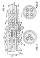
- Figure 4 is an enlarged longitudinal sectional view of the distal end portion of the syringe illustrated in Figure 1, but showing the various components immediately prior to coupling;
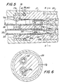
- Figure 5 is a further enlarged fragmentary cross-sectional view of a portion of the assembly illustrated in Figure 4 but illustrating the components in operative engagement providing fluid communication between the hose and syringe.
- Figure 6 is a transverse sectional view taken on line 6-6 of Figure 5;
- Figure 7 is a transverse sectional view, similar to Figure 6, but of a modified embodiment of the present invention;
- Figure 8 is a transverse sectional view, similar to Figure 7, but illustrating a further modified embodiment of the present invention; and
- Figure 9 is an enlarged fragmentary longitudinal sectional view of an improved flow control valve for use in a syringe according to the present invention.
- Referring now to the drawings, Figure 1 illustrates a syringe 10 which embodies the present invention. Outwardly, the syringe 10 is similar in appearance to the syringe illustrated in our US-A-4149315. As described in that patent, the syringe 10 is particularly suited for use in medical and dental applications where it is desired to flow either a fluid, such as water, or a gas such as air, into a body cavity, such as an oral cavity in a dental surgery. As used herein, fluid is defined as either a compressible gas or an incompressible liquid.
- The syringe 10 comprises an elongate handle 11 having a proximal end portion 11a to which is secured a
nozzle 12 from which a fluid may be flowed, such as in the manner described in the aforementioned patent. The proximal end portion, or valve body head, 11a of the handle 11 also has one or more push button control valves having finger actuators, such as theactuators distal end portion 11b connected to aflexible hose assembly 15. As shown in Figure 2, thehose assembly 15 includes atube 15a connected to a source of water (not shown) and atube 15b connected to a source of air (not shown). By selective operation of thevalve actuators nozzle 12 into a body cavity. - As discussed earlier, one of the problems associated with syringes of conventional design is that they are not capable readily of being connected to and disconnected from the air and water
supply hose assembly 15. Thus, even though some may have nozzles that can be disconnected for sterilisation, the handle portions usually remain firmly connected to the hose assembly. Thus, they are difficult to sterilize effectively. - The present invention overcomes the aforementioned drawbacks associated with conventional syringes by providing a syringe which can be quickly connected to and disconnected from a flexible hose assembly without requiring any special tools. This enables the entire syringe to be removed from the dental or medical surgery for sterilisation in an autoclave. As a result, the syringe, and particularly the proximal end portions thereof which are normally placed in close proximity with a body cavity, can be sterilised readily and effectively.
- To this end, a coupling means 16 (Figure 2) is provided for releasably coupling the
distal end portion 11b of the handle 11 to thehose assembly 15. In the illustrated embodiment (Figure 4) this is accomplished by first andsecond coupling components 16a, 16b which are telescopically matingly engageable and disengageable with one another and which have cooperating valving and actuator means operable automatically upon engagement to provide fluid communication between thehose assembly 15 and the handle 11 when interconnected and to block fluid communication when disconnected. The first and second coupling components providing the coupling means 16 are indicated generally within the region denominated by thereference numeral 16 in Figure 2. As best seen in Figure 4 the first coupling component 16a is carried on end portions of thehoses second coupling component 16b is carried on thedistal end portion 11b of the syringe handle 11. The first coupling component 16a is provided by a frusto-conical (or cylindrical)body 17 having a pair ofvalve chambers 17a, 17b each of which telescopically receives a union, such as theunions 19a and 19b, respectively. Theunions 19a and 19b have ridged portions, engaged inside the end portions of thehoses - For enabling flow rate adjustments to be made, a
pinch valve assembly 22 is provided on the upstream side of thecoupling body 17. As best seen in Figure 4, thepinch valve assembly 22 includes avalve block 25 having a pair of through bores which receive thehose end portions unions 19a and 19b in the manner illustrated. As best seen in Figure 3, thepinch valve assembly 22 includes a pair ofset screws pinch valve block 25. Theset screws hoses - To mount the
pinch valve assembly 22, thecoupling component body 17 has an externally threadedportion 17c which rotatably receives a complementary threaded portion of atubular ferrule 26. Theferrule 26 has an open end 26a rotatably receiving thenose end portions ferrule 26 secures the pinchvalve block assembly 22 in position at the right, or upstream, end of thecoupling body 17 for causing either air and water under pressure to be supplied continuously to thevalve chambers 17a and 17b, respectively at a preselected flow rate. - In order to block fluid flow from the
valve chambers 17a and 17b when thecoupling components 16a and 16b are disconnected, each valve chamber is provided with a valve member movable between a seated position illustrated in Figure 4 and an unseated position illustrated in Figure 5. Each valve member, such as thevalve member 28 associated with thechamber 17b, has a head 28a mounting an O-ring 29 adapted to engage aseat 30 confronting thevalve chamber 17b. In the illustrated embodiment, thevalve member 28 is preferably of hollow tubular form having acentral passage 28b which communicates adjacent its head 28a with a pair oflateral ports 28c (Figure 6). Thevalve member 28 has aperipheral flange 28′ at the end opposite its head 28a which surrounds anaxial end port 28d. Ahelical compression spring 31 is engaged between theflange 28′ and a shoulder in a bore slidably receiving thevalve member 28 to bias thevalve member 28 into its closed position illustrated in Figure 4. In such position, thelateral ports 28c are sealed from thevalve chamber 17b by the engagement of the O-ring 29 with itsseat 30. Thevalve member 32 associated with the other chamber 17a is of like construction and operates in the same manner as thevalve 28. Thus, bothvalves chambers 17a and 17b until actuated. - For the purpose of unseating the
valves valve chambers 17b and 17a, respectively and thesyringe nozzle 12, actuator means is provided in thesecond coupling component 16b on the handle 11. In the illustrated embodiment, as best seen in Figure 4, the actuator means includes a pair ofconduits distal end portion 11b. In the present instance, thesecond coupling component 16b is provided by atubular extension wall 18 which is located on thedistal end 11b of the handle 11 and which surrounds the end portions of theconduits distal end 11b of the handle 11. Thecoupling component body 17 has aboss 17d which is sized to be telescopically received within the recess 18a. When initially arranged in the manner illustrated in Figure 4,passages 35b, 36b in theconduits valves conduits valves valves rings 37 and 38 are mounted in grooves in thecoupling component body 17 and surround the outer peripheries of theconduits - To provide a desirable snap-together releasable connection, a split
circular spring ring 40 is mounted in a groove on thedownstream end 17d of thecoupling component body 17, and thespring 40 is adapted to engage in an interior groove 18b in the othercoupling component wall 18 in the manner illustrated in Figure 5 when thecoupling components 16a and 16b are matingly telescopically engaged with one another. Preferably, thespring rate 40 and its complementary groove 18b are designed to provide a snap-together connection which keeps the components connected under gauge fluid pressures as high as 5.6 kg/cm² (80 psig), but permits disconnection at an axial force of at least 3.63 kg (8 lbs.), but less than about 7.25 kg (16 lbs.). - When the
coupling components 16a and 16b are matingly engaged, the valves and valve actuators are in the positions illustrated in Figure 5. In such position, both thevalve members ends 35′, 36′ of theconduits valve cavities 17a, 17b, into the lateral ports of thevalve members tubes nozzle 12 by selective actuation of thevalve actuators coupling component 16b disconnected from the coupling component 16a on thehose assembly 15. When pulled apart, theconduits valves valve chambers 17a and 17b. The thus-removed syringe 10 can be sterilised by conventional techniques, such as the application of high temperature steam in an autoclave, heat in a chemiclave, or dry heat in a dry heat steriliser. - In the embodiment of Figures 1 to 6, air and water are supplied to the nozzle via the two valved flow paths illustrated. If desired, however, warm water may be continually supplied to the proximal end of the syringe 10 by flowing it forwardly through one conduit to the proximal end portion 11a of Figure 1 through a T-connection and returning any unused portion rearwardly through a third exit conduit in the handle 11 to maintain continuity of flow, and hence constant delivery temperature. In such event, three conduits and complementary valve assemblies may be provided and arranged such as in the manner illustrated in cross-section in Figure 7. In this embodiment, three valve actuators are provided, one for air, a second for warm water input and a third for the exit of return water.
- If desired, a plurality of conduits for various purposes may be provided in the handle of the syringe with each being provided with its own flow control valve. For instance, one of the conduits may be used to supply air to the nozzle, another to supply either warm or cool water, and a third to supply a liquid medicament. A fourth conduit may be provided and utilised either as a return for warm water, or possibly, to provide a mouth wash deliverable from the
nozzle 12. Still another combination for use in dentistry is to provide compressed air, pressurised water, a local topical anaesthetic, and a mouth wash. In medical applications, for example, in cleaning and preparing infected wounds, such as the treatment of decubitus skin ulcers, a source of nitrogen gas, sterile and distilled water, a debridement agent, such as, hydrogen peroxide, and medicament are used. Such combination can be provided on a mobile cart delivery system with the supply of all four fluids contained in pressurized canisters which will permit convenient bedside use in a hospital setting. The advantage of syringe delivery is that this method minimizes the potential of wound recontamination during the debridement and treatment procedure. These four conduits may be arranged as illustrated in cross-section in Figure 8. - In the illustrated embodiment, the snap-together type connection is provided by a split circular spring ring carried on one component and an interior complementary mating groove in the other. If desired, however, other means may be provided which afford rapid connection and disconnection without the use of tools. For instance, ball detent mechanisms, bayonet-type connections, O-ring type mechanisms and high pitch threads may be used, as desired. In the disclosed embodiment, the O-rings are of a material that resists repeated subjection to high temperatures, such as the 316°C (600°F) temperature in a sterilisation process. The preferred material is a fluorocarbon manufactured under the trade designation VITON. Various other parts of the syringe are preferably fabricated of plated brass, stainless steel and/or hard anodised aluminium.
- Over a prolonged period of time, repeated subjection of the syringe to the high temperatures associated with autoclave or other sterilisation methods may cause the O-rings associated with the
flow control valves flow control valves - Except for the novel construction of the flow control valves, to be described, and the coupling means described heretofore, the
syringe 110 illustrated in Figure 9 is otherwise structurally the same as that illustrated in Figures 1 and 4 of US-A-4149315. The flow control valve illustrated in Figure 5 of that patent is fabricated of a series of components which are assembled in a manner which prevents them from being disassembled in the field. As a result, the flow control valve in the prior art structure must be removed, discarded and replaced when worn. Not only is this economically undesirable, but the flow control valve structure itself is not inexpensive to manufacture. - Therefore, a flow control valve is provided which can be manufactured economically and removed easily in the field for replacement of O-rings, and while it is particularly suited for the autoclavable syringe illustrated in Figures 1 to 8, it may also be used in a syringe such as described in US-A-4149315.
- Referring now to Figure 9, a
syringe 110 having a handle 111 with a proximal end portion 111a and anozzle 112 is provided with a flowcontrol valve assembly 150. - The flow
control valve assembly 150 is mounted in a recess provided by a circular cylindrical wall 111′ in the proximal end 111a of thesyringe 110 for controlling fluid flow between the conduits in the handle 111 and thenozzle 112 in the same manner as described in US-A-4149315. Thevalve assembly 150 includes a one-piece valve body 151 having atubular side wall 152 and anend wall 153. Thetubular side wall 152 has an outerperipheral groove 152a and one ormore ports 152b opening into acentral cavity 154. Theend wall 153 has an axial port 153a which also communicates with thecavity 154. A pair of axially spacedgrooves ports 152b and mount O-rings body side wall 152 is provided with anannular flange 152e having agroove 152f which is engageable by aset screw 157 for removably mounting thevalve body 151 in place. - The desired valving action is provided by a
valve element 160 having a stem 160a which extends through the axial port 153a and terminates at its lower end in ahead 160b. Thehead 160b has a peripheral groove which mounts an O-ring 161. The upper end of the stem 160a is formed integrally with afinger actuator 162 having anenlarged button portion 162a overlying part of the proximal end 111a of thesyringe 110. An O-ring 163 is mounted in a groove in theactuator 162. The O-ring 161 in the head of thevalve element 160 is normally biased into engagement with theend wall 153 around the axial port 153a by means of ahelical compression spring 165 mounted in thevalve cavity 154 and engaged between theend wall 153 and a shoulder on thevalve actuator 162. The O-ring 161 on thehead 160b provides the sole means for retaining thevalve actuator 162 engaged with thevalve body 161. As a result, after theset screw 157 is backed-off and the flowcontrol valve assembly 150 removed from its recess, thevalve assembly 150 can be disassembled first by disconnecting the O-ring 161 from thevalve head 160b and then sliding theactuator 162 axially outward. The O-rings actuator 162 reinstalled, and the O-ring 161 replaced, and thevalve assembly 150 reinstalled and secured in place by means of theset screw 157. The flowcontrol valve assembly 150 is particularly suited for use in the autoclavable syringe 10 of Figures 1 to 8, but because of its essentially two-piece machined construction having replaceable O-rings, it may also be used readily in a conventional syringe which is not normally subjected to the high temperatures associated with sterilisation in an autoclave. The relatively simple structure of the flowcontrol valve assembly 150 renders it straightforward to manufacture by high speed mass production machinery thereby enabling significant manufacturing cost savings to be realised. - In view of the foregoing, it should be apparent that the present invention now provides an improved syringe which is particularly suited for sterilisation methods known to date, including treatment in an autoclave. This is due to its capability of being readily disconnected from compressible gas (including air) and incompressible liquid (including water) supply hoses, and because of other design features which both resist the high temperatures and increased chemical reaction rates at higher temperatures encountered in sterilisation procedures and afford field parts replacement should such become necessary after repeated sterilisation cycles. Thus, the syringe of the present invention may find widespread applicability, not only in a dental surgery (or operatory), but also in the medical field where surgical procedures are performed in hospital operating rooms and nursing care delivered at bedside and where sterile areas must be maintained.
- While preferred embodiments of the present invention have been described in detail, various modifications, alterations and changes may be made without departing from the scope of the following claims.
Claims (17)
Applications Claiming Priority (2)
| Application Number | Priority Date | Filing Date | Title |
|---|---|---|---|
| US07/260,932 US4957483A (en) | 1988-10-21 | 1988-10-21 | Sterilizable syringe |
| US260932 | 2005-10-27 |
Publications (2)
| Publication Number | Publication Date |
|---|---|
| EP0365300A2 true EP0365300A2 (en) | 1990-04-25 |
| EP0365300A3 EP0365300A3 (en) | 1991-09-04 |
Family
ID=22991256
Family Applications (1)
| Application Number | Title | Priority Date | Filing Date |
|---|---|---|---|
| EP19890310701 Withdrawn EP0365300A3 (en) | 1988-10-21 | 1989-10-18 | Sterilisable syringe |
Country Status (5)
| Country | Link |
|---|---|
| US (1) | US4957483A (en) |
| EP (1) | EP0365300A3 (en) |
| JP (1) | JPH02172550A (en) |
| CA (1) | CA1333875C (en) |
| MX (1) | MX165497B (en) |
Cited By (2)
| Publication number | Priority date | Publication date | Assignee | Title |
|---|---|---|---|---|
| WO2000035370A1 (en) * | 1998-12-17 | 2000-06-22 | Segal Alan J | Handpiece for a dental syringe assembly |
| EP1434620A4 (en) * | 2001-10-09 | 2005-04-13 | Halkey Roberts Corp | Male luer valve |
Families Citing this family (84)
| Publication number | Priority date | Publication date | Assignee | Title |
|---|---|---|---|---|
| US5045055A (en) * | 1988-10-21 | 1991-09-03 | Den-Tal-Ez, Inc. | Flow control valve assembly for syringes |
| USD322670S (en) | 1989-01-03 | 1991-12-24 | Hans Grohe Gmbh & Co. Kg | Combined dental syringe, nozzles and control unit |
| US5391145A (en) * | 1990-01-26 | 1995-02-21 | Dorsey, Iii; James H. | Irrigation control valve for endoscopic instrument |
| US5090904A (en) * | 1990-02-09 | 1992-02-25 | Young Dental Manufacturing Company | Autoclavable air polisher handpiece |
| FR2666988A1 (en) * | 1990-09-20 | 1992-03-27 | Bailly Alain | EQUIPMENT FOR SYRINGES FOR SPRAYING A MIXTURE OF FLUIDS USED, IN PARTICULAR, IN DENTAL ART. |
| US5224929A (en) * | 1990-12-21 | 1993-07-06 | C. R. Bard, Inc. | Irrigation/aspiration cannula and valve assembly |
| US5433485A (en) * | 1991-02-22 | 1995-07-18 | A-Dec, Inc. | Syringe tip retainer assembly |
| US5125835A (en) * | 1991-06-25 | 1992-06-30 | Dental Components, Inc. | Dental syringe with finger actuated tip retainer assembly |
| US5184652A (en) * | 1991-07-02 | 1993-02-09 | Fan Chin Fu | Universal medication port |
| AT396742B (en) * | 1991-09-13 | 1993-11-25 | Intec Innovative Med Tech | DENTAL HANDPIECE |
| DE4138673C1 (en) * | 1991-11-25 | 1993-03-11 | Kaltenbach & Voigt Gmbh & Co, 7950 Biberach, De | |
| US5514110A (en) * | 1993-03-22 | 1996-05-07 | Teh; Eutiquio L. | Automatic flow control device |
| US6746419B1 (en) | 1993-04-19 | 2004-06-08 | Stryker Corporation | Irrigation handpiece with built in pulsing pump |
| US5470305A (en) | 1993-04-19 | 1995-11-28 | Stryker Corporation | Irrigation handpiece with built in pulsing pump |
| US5401245A (en) * | 1993-11-26 | 1995-03-28 | Haining; Michael L. | Medical connector with valve |
| US5785693A (en) * | 1993-11-26 | 1998-07-28 | Haining; Michael L. | Medical connector |
| US5533983A (en) * | 1993-11-26 | 1996-07-09 | Haining; Michael L. | Valved medical connector |
| US6213970B1 (en) | 1993-12-30 | 2001-04-10 | Stryker Corporation | Surgical suction irrigation |
| US5501596A (en) * | 1994-07-27 | 1996-03-26 | Young Dental Manufacturing Company, Inc. | Autoclavable dental scaler handpiece |
| US5722949A (en) * | 1994-08-26 | 1998-03-03 | Sanese Medical Corporation | Fluid supply and suction apparatus and method |
| US5554111A (en) * | 1995-03-16 | 1996-09-10 | Mayo Foundation For Medical Education & Research | Bone cleaning and drying system |
| US5685851A (en) * | 1995-06-06 | 1997-11-11 | Eams Industries, Inc. | Irrigation syringe |
| USD373636S (en) | 1995-08-24 | 1996-09-10 | Howard Martin | Root canal handpiece |
| US7320594B1 (en) * | 1995-08-31 | 2008-01-22 | Biolase Technology, Inc. | Fluid and laser system |
| US5847734A (en) | 1995-12-04 | 1998-12-08 | Pawlowski, Jr.; Norman E. | Air purge system for an ink-jet printer |
| US5771053A (en) | 1995-12-04 | 1998-06-23 | Hewlett-Packard Company | Assembly for controlling ink release from a container |
| US5900895A (en) | 1995-12-04 | 1999-05-04 | Hewlett-Packard Company | Method for refilling an ink supply for an ink-jet printer |
| US5815182A (en) | 1995-12-04 | 1998-09-29 | Hewlett-Packard Company | Fluid interconnect for ink-jet pen |
| US5732751A (en) | 1995-12-04 | 1998-03-31 | Hewlett-Packard Company | Filling ink supply containers |
| US5799700A (en) * | 1996-06-27 | 1998-09-01 | Teh; Eutiquio L. | Automatic intravenous flow control device |
| US5944520A (en) * | 1996-08-29 | 1999-08-31 | Ash; Albert | Dental hand piece with internal back flow prevention valve |
| US5848893A (en) * | 1996-10-18 | 1998-12-15 | Martin; Daniel H. | Dental spray syringe |
| US6099494A (en) | 1997-08-20 | 2000-08-08 | Stryker Corporation | Pulsed irrigator useful for surgical and medical procedures |
| KR100301169B1 (en) * | 1999-02-24 | 2001-09-22 | 성영동 | Foaming gun for rolyurethane solution |
| US6485451B1 (en) | 2000-08-02 | 2002-11-26 | Welch Allyn, Inc. | Body cavity irrigation system |
| US6652488B1 (en) | 2000-09-11 | 2003-11-25 | Stryker Corporation | Surgical suction irrigator |
| US6382970B1 (en) | 2001-01-19 | 2002-05-07 | Stephen A. Foster | Dental air/water syringe purge device |
| US6458094B1 (en) | 2001-04-11 | 2002-10-01 | Welch Allyn, Inc. | Disposable tip for body cavity irrigation system |
| US10022078B2 (en) | 2004-07-13 | 2018-07-17 | Dexcom, Inc. | Analyte sensor |
| US6824385B1 (en) * | 2003-05-05 | 2004-11-30 | Dentech Corporation | Dental syringe apparatus and method |
| US7285110B2 (en) * | 2003-06-10 | 2007-10-23 | P. Rowan Smith, Jr. | Retractable hypodermic safety syringe |
| US7591801B2 (en) | 2004-02-26 | 2009-09-22 | Dexcom, Inc. | Integrated delivery device for continuous glucose sensor |
| US8886273B2 (en) | 2003-08-01 | 2014-11-11 | Dexcom, Inc. | Analyte sensor |
| US8626257B2 (en) | 2003-08-01 | 2014-01-07 | Dexcom, Inc. | Analyte sensor |
| US20190357827A1 (en) | 2003-08-01 | 2019-11-28 | Dexcom, Inc. | Analyte sensor |
| US7920906B2 (en) | 2005-03-10 | 2011-04-05 | Dexcom, Inc. | System and methods for processing analyte sensor data for sensor calibration |
| US20050048436A1 (en) * | 2003-08-29 | 2005-03-03 | Udi Fishman | Handpiece apparatus and method for dispensing media |
| US9247900B2 (en) | 2004-07-13 | 2016-02-02 | Dexcom, Inc. | Analyte sensor |
| US8423114B2 (en) | 2006-10-04 | 2013-04-16 | Dexcom, Inc. | Dual electrode system for a continuous analyte sensor |
| US8364231B2 (en) | 2006-10-04 | 2013-01-29 | Dexcom, Inc. | Analyte sensor |
| US11633133B2 (en) | 2003-12-05 | 2023-04-25 | Dexcom, Inc. | Dual electrode system for a continuous analyte sensor |
| US8532730B2 (en) | 2006-10-04 | 2013-09-10 | Dexcom, Inc. | Analyte sensor |
| US8425416B2 (en) | 2006-10-04 | 2013-04-23 | Dexcom, Inc. | Analyte sensor |
| US8425417B2 (en) | 2003-12-05 | 2013-04-23 | Dexcom, Inc. | Integrated device for continuous in vivo analyte detection and simultaneous control of an infusion device |
| US8287453B2 (en) | 2003-12-05 | 2012-10-16 | Dexcom, Inc. | Analyte sensor |
| US8364230B2 (en) | 2006-10-04 | 2013-01-29 | Dexcom, Inc. | Analyte sensor |
| US8808228B2 (en) | 2004-02-26 | 2014-08-19 | Dexcom, Inc. | Integrated medicament delivery device for use with continuous analyte sensor |
| US7783333B2 (en) | 2004-07-13 | 2010-08-24 | Dexcom, Inc. | Transcutaneous medical device with variable stiffness |
| US8886272B2 (en) | 2004-07-13 | 2014-11-11 | Dexcom, Inc. | Analyte sensor |
| US8989833B2 (en) | 2004-07-13 | 2015-03-24 | Dexcom, Inc. | Transcutaneous analyte sensor |
| USD533274S1 (en) | 2004-10-12 | 2006-12-05 | Allegiance Corporation | Handle for surgical suction-irrigation device |
| DK1928517T3 (en) * | 2005-09-27 | 2017-03-13 | Allegiance Corp | HAND PIECE FOR MEDICAL SUCCESS AND RINSE DEVICE |
| US8478377B2 (en) | 2006-10-04 | 2013-07-02 | Dexcom, Inc. | Analyte sensor |
| US8447376B2 (en) | 2006-10-04 | 2013-05-21 | Dexcom, Inc. | Analyte sensor |
| US8298142B2 (en) | 2006-10-04 | 2012-10-30 | Dexcom, Inc. | Analyte sensor |
| US8562528B2 (en) | 2006-10-04 | 2013-10-22 | Dexcom, Inc. | Analyte sensor |
| US8449464B2 (en) | 2006-10-04 | 2013-05-28 | Dexcom, Inc. | Analyte sensor |
| US8275438B2 (en) | 2006-10-04 | 2012-09-25 | Dexcom, Inc. | Analyte sensor |
| CA2688184A1 (en) | 2007-06-08 | 2008-12-18 | Dexcom, Inc. | Integrated medicament delivery device for use with continuous analyte sensor |
| EP4159114B1 (en) | 2007-10-09 | 2024-04-10 | DexCom, Inc. | Integrated insulin delivery system with continuous glucose sensor |
| US8396528B2 (en) | 2008-03-25 | 2013-03-12 | Dexcom, Inc. | Analyte sensor |
| US9149220B2 (en) | 2011-04-15 | 2015-10-06 | Dexcom, Inc. | Advanced analyte sensor calibration and error detection |
| US20100211010A1 (en) * | 2009-02-18 | 2010-08-19 | Michael Wycoki | Topical anesthetic and antiseptic dispensing device |
| JP2011036769A (en) * | 2009-08-07 | 2011-02-24 | Meiji Kikai Seisakusho:Kk | Spray gun |
| USD667554S1 (en) * | 2010-07-05 | 2012-09-18 | Societe Our la Conception des Applications des Techniques Electroniques-Satelec | Dental airpolisher gun |
| US9289319B2 (en) * | 2012-05-14 | 2016-03-22 | Abbott Cardiovascular Systems Inc. | Flow regulation valve for controlling inflation rate of a balloon deploying a scaffold |
| DE102012106666B4 (en) * | 2012-07-23 | 2017-06-01 | MEDTRONIC medizinisch-elektronische Geräte-Gesellschaft mit beschränkter Haftung | Coupling device for connecting a supply hose for dental instruments with a supply and control unit |
| US20150216622A1 (en) * | 2014-02-05 | 2015-08-06 | Albert Vartanian | Ergonomically optimized, in-line water valve assembly for use with a dental handpiece |
| EP3324875B1 (en) * | 2016-06-22 | 2018-11-28 | Kaltenbach & Voigt GmbH | Dental treatment and/or examination assembly, dental coupling unit and method for rinsing the liquid pumping system of a dental treatment and/or examination assembly |
| US10368579B2 (en) * | 2017-05-01 | 2019-08-06 | Yongjie James Xu | Microvaporizer quick-release mechanism |
| DK3928687T3 (en) | 2017-10-24 | 2024-09-30 | Dexcom Inc | PORTABLE DEVICE WITH PRE-CONNECTED ANALYTIC SENSOR |
| US11331022B2 (en) | 2017-10-24 | 2022-05-17 | Dexcom, Inc. | Pre-connected analyte sensors |
| KR102142041B1 (en) * | 2020-03-20 | 2020-08-06 | 박봉수 | Dental syringe |
| WO2026061863A1 (en) * | 2024-09-23 | 2026-03-26 | Koninklijke Philips N.V. | Valve system for dental cleaning appliance head-handle interface |
Family Cites Families (15)
| Publication number | Priority date | Publication date | Assignee | Title |
|---|---|---|---|---|
| US2029734A (en) * | 1933-07-31 | 1936-02-04 | Oscar H Pieper | Dental syringe |
| US2628850A (en) * | 1949-03-19 | 1953-02-17 | Donald V Summerville | Releasable conduit connection with automatic valving |
| US2571856A (en) * | 1949-06-15 | 1951-10-16 | Freedman Hyman | Dental appliance |
| GB984561A (en) * | 1960-03-07 | 1965-02-24 | Amalgamated Dental Co Ltd | Dental equipment |
| US3254646A (en) * | 1962-08-20 | 1966-06-07 | American Hospital Supply Corp | Dental syringes |
| US3357599A (en) * | 1966-02-11 | 1967-12-12 | George B Douglas | Commercial type hair lotion applicator |
| US3500824A (en) * | 1967-03-16 | 1970-03-17 | Hydro Mfg Inc | Oral hydrotherapeutic apparatus |
| US3570483A (en) * | 1967-10-30 | 1971-03-16 | Dentsply Int Inc | Dental syringe with releasable hose coupling |
| US3698088A (en) * | 1969-10-24 | 1972-10-17 | George K Austin Jr | Dental syringes |
| US4026025A (en) * | 1975-10-28 | 1977-05-31 | Hunt Roderick S | Dental syringe |
| US4149315A (en) * | 1977-02-14 | 1979-04-17 | Den-Tal-Ez Mfg. Co. | Dental syringe |
| DE2855719A1 (en) * | 1978-12-22 | 1980-07-10 | Siemens Ag | DENTAL HANDPIECE ARRANGEMENT |
| US4403959A (en) * | 1981-07-31 | 1983-09-13 | Kabushiki Kaisha Yoshida Seisakusho | Coupling device for a dental instrument |
| JPS6190650A (en) * | 1984-10-12 | 1986-05-08 | 株式会社 吉田製作所 | Dental treating apparatus |
| DE3734864C2 (en) * | 1987-10-14 | 1994-06-09 | Kaltenbach & Voigt | Dental spray handpiece |
-
1988
- 1988-10-21 US US07/260,932 patent/US4957483A/en not_active Expired - Fee Related
-
1989
- 1989-09-22 CA CA000612606A patent/CA1333875C/en not_active Expired - Fee Related
- 1989-10-18 EP EP19890310701 patent/EP0365300A3/en not_active Withdrawn
- 1989-10-20 JP JP1271946A patent/JPH02172550A/en active Pending
- 1989-10-20 MX MX018047A patent/MX165497B/en unknown
Cited By (5)
| Publication number | Priority date | Publication date | Assignee | Title |
|---|---|---|---|---|
| WO2000035370A1 (en) * | 1998-12-17 | 2000-06-22 | Segal Alan J | Handpiece for a dental syringe assembly |
| GB2359258A (en) * | 1998-12-17 | 2001-08-22 | Segal Alan J | Handpiece for a dental syringe assembly |
| US6500000B1 (en) | 1998-12-17 | 2002-12-31 | Alan Julian Segal | Handpiece for a dental syringe assembly |
| GB2359258B (en) * | 1998-12-17 | 2003-11-19 | Segal Alan J | Handpiece for a dental syringe assembly |
| EP1434620A4 (en) * | 2001-10-09 | 2005-04-13 | Halkey Roberts Corp | Male luer valve |
Also Published As
| Publication number | Publication date |
|---|---|
| US4957483A (en) | 1990-09-18 |
| JPH02172550A (en) | 1990-07-04 |
| MX165497B (en) | 1992-11-13 |
| EP0365300A3 (en) | 1991-09-04 |
| CA1333875C (en) | 1995-01-10 |
Similar Documents
| Publication | Publication Date | Title |
|---|---|---|
| EP0365300A2 (en) | Sterilisable syringe | |
| US5045055A (en) | Flow control valve assembly for syringes | |
| AU674706B2 (en) | Portable sterilizable water supply for dental appliances | |
| US5247966A (en) | Suction irrigator valve apparatus | |
| CA2157935C (en) | Minimally invasive irrigator/aspirator surgical probe and method of using same | |
| KR101092805B1 (en) | Respiratory apparatus having an introduction section configured for releasable attachment with a respiratory instrument | |
| CA2146122C (en) | Water purification system for dental instrument | |
| US5397314A (en) | Surgical cannula with ball valve | |
| US6364853B1 (en) | Irrigation and suction valve and method therefor | |
| US5288290A (en) | Multi-ported valve assembly | |
| EP0389818B1 (en) | Medical evacuation and irrigation device | |
| EP1551487B1 (en) | Improved respiratory valve | |
| US20050043690A1 (en) | Cannula that provides bi-directional fluid flow that is regulated by a single valve | |
| GB2268072A (en) | Suction/irrigation instrument having reusable handle with disposable fluid path | |
| US5234338A (en) | Autoclavable head and handle for dental syringe | |
| US6500000B1 (en) | Handpiece for a dental syringe assembly | |
| US6302692B1 (en) | Multi-valve dental handpiece supply reservoir | |
| WO1997001367A1 (en) | Bag in pressure chamber arrangement for use in anaesthesia and resuscitation apparatus | |
| US6290498B1 (en) | Water valve for dental handpiece | |
| WO2001054611A2 (en) | Water valve for dental handpiece |
Legal Events
| Date | Code | Title | Description |
|---|---|---|---|
| PUAI | Public reference made under article 153(3) epc to a published international application that has entered the european phase |
Free format text: ORIGINAL CODE: 0009012 |
|
| AK | Designated contracting states |
Kind code of ref document: A2 Designated state(s): DE FR GB IT |
|
| RAP3 | Party data changed (applicant data changed or rights of an application transferred) |
Owner name: DEN-TAL-EZ, INC. |
|
| PUAL | Search report despatched |
Free format text: ORIGINAL CODE: 0009013 |
|
| AK | Designated contracting states |
Kind code of ref document: A3 Designated state(s): DE FR GB IT |
|
| 17P | Request for examination filed |
Effective date: 19920130 |
|
| 17Q | First examination report despatched |
Effective date: 19930906 |
|
| STAA | Information on the status of an ep patent application or granted ep patent |
Free format text: STATUS: THE APPLICATION IS DEEMED TO BE WITHDRAWN |
|
| 18D | Application deemed to be withdrawn |
Effective date: 19950125 |