EP0365301B1 - Verfahren und Gerät für Bilddarstellungen - Google Patents
Verfahren und Gerät für Bilddarstellungen Download PDFInfo
- Publication number
- EP0365301B1 EP0365301B1 EP89310703A EP89310703A EP0365301B1 EP 0365301 B1 EP0365301 B1 EP 0365301B1 EP 89310703 A EP89310703 A EP 89310703A EP 89310703 A EP89310703 A EP 89310703A EP 0365301 B1 EP0365301 B1 EP 0365301B1
- Authority
- EP
- European Patent Office
- Prior art keywords
- cells
- radiation
- array
- radiation sensitive
- examination region
- Prior art date
- Legal status (The legal status is an assumption and is not a legal conclusion. Google has not performed a legal analysis and makes no representation as to the accuracy of the status listed.)
- Expired - Lifetime
Links
Images


Classifications
-
- A—HUMAN NECESSITIES
- A61—MEDICAL OR VETERINARY SCIENCE; HYGIENE
- A61B—DIAGNOSIS; SURGERY; IDENTIFICATION
- A61B6/00—Apparatus or devices for radiation diagnosis; Apparatus or devices for radiation diagnosis combined with radiation therapy equipment
- A61B6/52—Devices using data or image processing specially adapted for radiation diagnosis
- A61B6/5205—Devices using data or image processing specially adapted for radiation diagnosis involving processing of raw data to produce diagnostic data
-
- A—HUMAN NECESSITIES
- A61—MEDICAL OR VETERINARY SCIENCE; HYGIENE
- A61B—DIAGNOSIS; SURGERY; IDENTIFICATION
- A61B6/00—Apparatus or devices for radiation diagnosis; Apparatus or devices for radiation diagnosis combined with radiation therapy equipment
- A61B6/02—Arrangements for diagnosis sequentially in different planes; Stereoscopic radiation diagnosis
- A61B6/03—Computed tomography [CT]
- A61B6/032—Transmission computed tomography [CT]
-
- G—PHYSICS
- G01—MEASURING; TESTING
- G01T—MEASUREMENT OF NUCLEAR OR X-RADIATION
- G01T1/00—Measuring X-radiation, gamma radiation, corpuscular radiation, or cosmic radiation
- G01T1/29—Measurement performed on radiation beams, e.g. position or section of the beam; Measurement of spatial distribution of radiation
- G01T1/2914—Measurement of spatial distribution of radiation
- G01T1/2985—In depth localisation, e.g. using positron emitters; Tomographic imaging (longitudinal and transverse section imaging; apparatus for radiation diagnosis sequentially in different planes, steroscopic radiation diagnosis)
Definitions
- This invention relates to imaging apparatuses and methods. More particularly the invention relates to medical diagnostic imaging apparatuses and methods, especially computed tomography (CT) apparatuses and methods.
- CT computed tomography
- the invention finds application in conjunction with volumetric medical diagnostic imaging and will be described with particular reference thereto. However, it is to be appreciated that the invention also relates to single slice imaging, quality control examinations, and the like.
- CT apparatus i.e. scanners have included a plurality of discrete radiation detectors arranged in a ring, or a section of a ring that is rotatable, around a patient examination region.
- Each discrete detector included a scintillation crystal which received radiation traversing a selected slice of a patient in the examination region and converted the radiation energy into light.
- a solid state photodiode or vacuum photomultiplier tube converted the light emitted by the scintillation crystal into electrical signals indicative of the intensity of emitted light, hence, the intensity of received radiation.
- an imaging apparatus comprising: means defining an examination region; radiation source means for rotating a beam of radiation about the examination region; means for receiving radiation that has traversed the examination region and producing electrical signals indicative of the received radiation, said means for receiving including a plurality of segmented arrays of radiation sensitive cells; and image reconstruction means for reconstructing the electrical signals into an image representation, characterised in that each segmented array comprises a two dimensional regular grid of radiation sensitive cells on a common substrate, the grid having a plurality of columns of radiation sensitive cells which extend along a circumference of the examination region and a plurality of rows of radiation sensitive cells which extend in a direction lengthwise of the examination region.
- a method of imaging comprising: rotating a fan beam of radiation about an examination region and thereby around an object to be imaged disposed therein; detecting radiation which has traversed the object using detection means comprising a plurality of segmented arrays of radiation sensitive cells; reading radiation absorption data from the detection means; and reconstructing an image representation from the read data, characterised in that each segmented array used in said method comprises a two dimensional regular grid of radiation sensitive cells on a common substrate, the grid having a plurality of columns of radiation sensitive cells which extend along a circumference of the examination region and a plurality of rows of radiation sensitive cells which extend in a direction lengthwise of the examination region.
- One advantage of the present invention resides in the generation of volumetric data for a volume that may be defined by the fan beam projection of an x-ray source moving in a circular path as the position of a patent table is incremented.
- the x-ray source may move continuously in a circular path as the table also moves continuously. This results in the source following a helical path around the patient relative to the patient. In such arrangements the x-ray flux utilization is increased and the total examination period for a given volume is significantly reduced.
- Another advantage of the present invention resides in its flexibility and imaging versatility. Multiple detectors can be grouped to maintain high photo efficiency while reducing the amount of data that has to be collected and processed. This can be done with a minimal reduction in resolution. If detectors are grouped in the axial direction, partial volume artifacts are significantly reduced over current scans of the same slice thickness.
- EP-A-0112475 discloses an imaging apparatus comprising: means defining an examination region; radiation source means for rotating a beam of radiation about the examination region; means for receiving radiation that has traversed the examination region and producing electrical signals indicative of the received radiation, said means for receiving including a plurality of segmented arrays of radiation sensitive cells; and image reconstruction means for reconstructing the electrical signals into an image representation.
- a CT scanner 10 selectively images cross sectional slices of a region of a patient supported on a stationary patient couch 12 within a scan circle or patient aperture 14.
- the patient couch is incremented to take a plurality of parallel slices.
- the couch moves continuously such that the patient is scanned along a helical path.
- An x-ray tube 16 for emitting a fan-shaped beam of radiation toward and spanning the scan circle 14 is mounted to a rotatable gantry 18.
- a multi spot x-ray tube may be utilized to increase the thickness of the fan beam or generate plural parallel beams.
- a collimator 20 defines the dimensions of the x-ray beam(s), particularly its width to select the thicknesses of an individual slice or group of slices which are imaged.
- An outer continuously adjustable collimator part 22 sets the overall width of the x-ray beam, i.e. the width of the outer slices. If the outer collimator part 22 is closed sufficiently, the outer slices may be eliminated and the center or inner slice(s) can be narrowed. If the halves of the outer collimator part 22 are moved independently, one of the outer slices may be eliminated and the other adjusted to a selected width, e.g. the width of the inner slice.
- An inner collimator part 24 selectively narrows the center or inner slice.
- the inner collimator part 24 has a fixed profile which is selectively moved into and out of the radiation beam.
- the fixed collimator segments may have selectable profiles such that the center slice collimation is adjustable.
- Other mechanical slice thickness adjustment or selection devices for the inner and outer slices may, of course, be utilized.
- a plurality of segmented detector array modules 30 receive radiation which has traversed the scan circle and provide output signals indicative of the intensity of received radiation.
- 128 detector modules each include three columns of 24 photodiodes to define three rings of 2,880 photodiodes per ring around the scan circle.
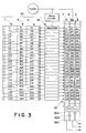
- each detector module includes three columns A, B, C of 24 x-ray sensitive cells each.
- the cells of column A are labelled A1-A24, etc.
- Other numbers of columns, such as five or more, may be provided and other numbers of radiation sensitive cells may be provided within each column without departing from the present invention.
- the center column B preferably is narrower than the side columns A and C. This enables the center column to have a higher resolution or define a narrower slice.
- the amount of radiation impinging on the outer columns A and C and the amount impinging on the inner column B are selectively adjustable. This enables the slice defined by the outer columns to be the same as the center column, wider, or narrower.
- each column there are a plurality of different height cells.
- taller cells A1, A3, A5,...A23, B1, B3,...B23, C1, C3,...C23 alternate with shorter cells A2, A4, A6...A24, B2, B4,...B24, C2, C4...C24.
- the radiation sensitive cells of the modules 30 are photodiodes.
- An array of charge injectors 32 periodically, at the sampling interval, recharges each photodiode of the array to a preselected charge level. As radiation impinges on the photodiodes, the charge is dissipated in proportion to the intensity of radiation and the duration of exposure.
- the injectors 32 At the end of each sampling interval when the injectors 32 recharge each photodiode, the injectors provide a like amount of charge to corresponding cells of a charge coupled device (CCD) array 34.
- the CCD array 34 has three columns of cells which in Figure 3 are labelled with the same designation as the corresponding photodiode of the photodiode array 30.
- the cells of the CCD array may be arranged in a different order than that of the corresponding diodes of the photodiode array to accommodate the order of data anticipated by downstream processing equipment.
- the CCD array is loaded with charge values indicative of the amount of charge necessary to recharge each photodiode to the preselected charge, i.e. the amount of charge dissipated.
- an indication of the charge remaining on each photodiode may be transferred to the CCD array.
- each charge value in the cells of each column, A, B, and C of the CCD array are shifted rapidly to charge amplifiers 36a, 36b, and 36c, respectively.
- each charge value is shifted in a time equal to 1/24th or less of the sampling interval. In this manner, the data from one sampling is converted to serial video signal data and the CCD array is ready to receive new data before the next sampling. If the three columns of cells are read serially rather than in parallel, the data is clocked out of each column three times as fast, such that all three columns are emptied before the next sampling.
- each buffer receives data serially from one of the rings.
- a combining means 46a,46b includes an intra-ring weighting and filtering means 46a for selectively weighting or filtering the data from the different sized cells of each ring.
- Algorithm means 48 converts the data into its logarithmic values. In the illustrated embodiment, three logarithmic circuits each process the data from one ring.
- the combining means 46a,46b further includes an axial combining means 46b for combining the data from the rings.
- the combining means selects a corresponding combination algorithm.
- the selected or combined data is reconstructed into an image representation by an image reconstruction means 50 such as a convolution and filtered back projection algorithm.
- the image representation may be stored in one or more image memories 52 for selective display on one or more video monitors 54.
- the image represen- tatons may be stored in computer memory, stored on tape, subject to further processing, or the like.
- the operator can select various imaging modes including single and multiple slice modes with different resolutions.
- the outputs of the rings are combined in various manners, both axially and transversely or processed independently.
- the outputs of each set of corresponding A, B, and C cells are combined.
- the outer collimator part 22 adjusts the outer slice width and the inner collimator part 24 sets the width of the center slice.
- the three rings of cells receive the radiation and produce output signals which could be used to produce three slices. Unless the center and outside columns of cells are exposed to the same amount of radiation, the three slices have different resolutions.
- the corresponding cells of the three rings are weighted to accommodate the different resolutions, summed, averaged, or the like. In an arrangement in which the center cells are three millimeters wide and the outer ones, four millimeters wide, this single slice technique is applicable to single slices with a width of about three to ten millimeters.
- the adjustable outer collimator part 22 or inner collimator part 24 may be utilized to reduce the width of the single slice below the width of the center column of cells.
- a multiple slice mode three slices are produced. That is, the data from each of the three rings of cells is processed separately.
- the center slice has the width of the center column of cells or the width defined by the inner collimator part 24.
- the width of the outer slices is separately adjusted by the outer collimator part 22. For many applications, it is advantageous to have all three slices the same width or resolution.
- two overlapping slices are produced. Data from corresponding cells of the center column and one column are combined to produce one set of data. Data from corresponding cells of the center column and the other side columm are also combined to produce a second set of data.
- the two sets of data, which represent overlapping slices, are processed separately. Again, the width of the slices may be adjusted with the collimator 20.
- transverse combinations of radiation sensitive cells can be selected.
- a spatially weighted view averaging mode adjacent different sized cells within the same ring A, B, or C are combined or weighted. This effectively averages the views from which the resultant image is reconstructed.
- a filtering mode the data from adjacent cells within each ring is time averaged or weighted.
- a view averaging mode the outputs of adjacent cells within each ring are summed or averaged without filtering or weighting.
- the views that are summed or averaged may be the time filtered or spatially weighted views described above.
- Various other imaging modes or combinations of these imaging modes may, of course, be selected.
- the logarithm may be taken earlier or later in the processing stream. Preferably, the logarithm is taken before an axial combination to reduce partial volume effects.
- the photodiode array 30 could alternatively be interconnected with an array of field effect transistor (FET) switches 60, rather than the CCD array as described above.
- FET field effect transistor
- the FETs are each connected with a respective one of the photodiodes for conveying an indication of the conductivity of the photodiode to one of the output amplifiers 36a, 36b and 36c.
- an instantaneous voltage across a photodiode and resistor combination is measured.
- other means besides a FET array or a CCD array may be provided for converting concurrently collected data into serial data signals.
Landscapes
- Health & Medical Sciences (AREA)
- Life Sciences & Earth Sciences (AREA)
- Engineering & Computer Science (AREA)
- Medical Informatics (AREA)
- Physics & Mathematics (AREA)
- High Energy & Nuclear Physics (AREA)
- Molecular Biology (AREA)
- Radiology & Medical Imaging (AREA)
- Animal Behavior & Ethology (AREA)
- Biophysics (AREA)
- Veterinary Medicine (AREA)
- Nuclear Medicine, Radiotherapy & Molecular Imaging (AREA)
- Optics & Photonics (AREA)
- Pathology (AREA)
- Public Health (AREA)
- Biomedical Technology (AREA)
- Heart & Thoracic Surgery (AREA)
- Surgery (AREA)
- General Health & Medical Sciences (AREA)
- Computer Vision & Pattern Recognition (AREA)
- General Physics & Mathematics (AREA)
- Spectroscopy & Molecular Physics (AREA)
- Pulmonology (AREA)
- Theoretical Computer Science (AREA)
- Apparatus For Radiation Diagnosis (AREA)
- Magnetic Resonance Imaging Apparatus (AREA)
- Image Processing (AREA)
- Image Analysis (AREA)
Claims (17)
Applications Claiming Priority (2)
| Application Number | Priority Date | Filing Date | Title |
|---|---|---|---|
| US07/260,403 US4965726A (en) | 1988-10-20 | 1988-10-20 | CT scanner with segmented detector array |
| US260403 | 1988-10-20 |
Publications (3)
| Publication Number | Publication Date |
|---|---|
| EP0365301A1 EP0365301A1 (de) | 1990-04-25 |
| EP0365301B1 true EP0365301B1 (de) | 1994-08-31 |
| EP0365301B2 EP0365301B2 (de) | 2002-09-25 |
Family
ID=22989022
Family Applications (1)
| Application Number | Title | Priority Date | Filing Date |
|---|---|---|---|
| EP89310703A Expired - Lifetime EP0365301B2 (de) | 1988-10-20 | 1989-10-18 | Verfahren und Gerät für Bilddarstellungen |
Country Status (4)
| Country | Link |
|---|---|
| US (1) | US4965726A (de) |
| EP (1) | EP0365301B2 (de) |
| JP (1) | JP3008356B2 (de) |
| DE (1) | DE68917846T3 (de) |
Families Citing this family (81)
| Publication number | Priority date | Publication date | Assignee | Title |
|---|---|---|---|---|
| US5166961A (en) * | 1988-10-20 | 1992-11-24 | Picker International, Inc. | CT scanner having multiple detector widths |
| US5262946A (en) * | 1988-10-20 | 1993-11-16 | Picker International, Inc. | Dynamic volume scanning for CT scanners |
| DE3843232A1 (de) * | 1988-12-22 | 1990-06-28 | Philips Patentverwaltung | Schaltungsanordnung zur geometrischen bildtransformation |
| IL90521A0 (en) * | 1989-06-04 | 1990-01-18 | Elscint Ltd | Dual slice scanner |
| US5396528A (en) * | 1991-06-28 | 1995-03-07 | General Electric Company | Tomographic image reconstruction using cross-plane rays |
| IL98945A0 (en) * | 1991-07-24 | 1992-07-15 | Elscint Ltd | Multiple slice ct scanner |
| US5241576A (en) * | 1991-12-23 | 1993-08-31 | General Electric Company | Segmented detector containing sub-elements for separate measuring of a fan beam |
| US5469486A (en) * | 1992-08-07 | 1995-11-21 | General Electric Company | Projection domain reconstruction method for helical scanning computed tomography apparatus with multi-column detector array employing overlapping beams |
| US5291402A (en) * | 1992-08-07 | 1994-03-01 | General Electric Company | Helical scanning computed tomography apparatus |
| JP3637074B2 (ja) * | 1992-12-15 | 2005-04-06 | 株式会社東芝 | ヘリカルスキャン方式のコンピュータ断層撮影装置 |
| US5355309A (en) * | 1992-12-30 | 1994-10-11 | General Electric Company | Cone beam spotlight imaging using multi-resolution area detector |
| JP3449561B2 (ja) * | 1993-04-19 | 2003-09-22 | 東芝医用システムエンジニアリング株式会社 | X線ct装置 |
| US5430784A (en) * | 1994-02-28 | 1995-07-04 | General Electric Company | Computerized tomography imaging using multi-slice detector with selectable slice thickness |
| US6047040A (en) * | 1994-07-29 | 2000-04-04 | Hu; Hui | Detector signal integration in volumetric CT scanner detector arrays |
| US6397098B1 (en) * | 1994-09-21 | 2002-05-28 | Medrad, Inc. | Data communication and control for medical imaging systems |
| US5840026A (en) * | 1994-09-21 | 1998-11-24 | Medrad, Inc. | Patient specific dosing contrast delivery systems and methods |
| US5592523A (en) * | 1994-12-06 | 1997-01-07 | Picker International, Inc. | Two dimensional detector array for CT scanners |
| JP2914891B2 (ja) * | 1995-07-05 | 1999-07-05 | 株式会社東芝 | X線コンピュータ断層撮影装置 |
| EP0809912B1 (de) * | 1995-12-18 | 2001-10-17 | Koninklijke Philips Electronics N.V. | Röntgenstrahluntersuchungsvorrichtung eine bildaufnahmematrix mit korrektureinheit enthaltend |
| US5974108A (en) * | 1995-12-25 | 1999-10-26 | Kabushiki Kaisha Toshiba | X-ray CT scanning apparatus |
| JP3455041B2 (ja) | 1995-12-25 | 2003-10-06 | 株式会社東芝 | X線ct装置 |
| US5867554A (en) * | 1996-06-20 | 1999-02-02 | Siemens Aktiengesellschaft | Spiral scan computed tomography apparatus having a modular surface detector for radiation |
| US5708691A (en) * | 1996-07-05 | 1998-01-13 | Kabushiki Kaisha Toshiba | X-ray computed tomographic imaging device and x-ray computed tomographic method |
| JP3763611B2 (ja) * | 1996-07-12 | 2006-04-05 | 株式会社東芝 | X線ctスキャナ |
| IL119033A0 (en) * | 1996-08-07 | 1996-11-14 | Elscint Ltd | Multi-slice detector array |
| JP3828967B2 (ja) * | 1996-10-30 | 2006-10-04 | 株式会社東芝 | X線ctスキャナ |
| JP3313611B2 (ja) * | 1997-05-06 | 2002-08-12 | ジーイー横河メディカルシステム株式会社 | 放射線断層撮影方法および装置 |
| US6115448A (en) * | 1997-11-26 | 2000-09-05 | General Electric Company | Photodiode array for a scalable multislice scanning computed tomography system |
| US6137857A (en) * | 1997-11-26 | 2000-10-24 | General Electric Company | Scalable detector for computed tomograph system |
| US6144718A (en) * | 1997-11-26 | 2000-11-07 | General Electric Company | Flexible cable connection for detector module |
| US6173031B1 (en) | 1997-11-26 | 2001-01-09 | General Electric Company | Detector modules for computed tomograph system |
| WO1999030616A1 (en) * | 1997-12-16 | 1999-06-24 | Koninklijke Philips Electronics N.V. | Computer tomography device |
| US5982846A (en) * | 1998-04-13 | 1999-11-09 | General Electric Company | Methods and apparatus for dose reduction in a computed tomograph |
| US6275562B1 (en) * | 1998-04-28 | 2001-08-14 | General Electric Company | Apparatus and methods for performing scalable multislice computed tomography scan |
| DE19832276C2 (de) * | 1998-07-17 | 2002-10-24 | Siemens Ag | Verfahren zur Rekonstruktion von aus mittels eines CT-Gerätes durch Spiralabtastung gewonnenen Meßwerten |
| DE19832275B4 (de) * | 1998-07-17 | 2006-09-14 | Siemens Ag | Verfahren zur Rekonstruktion von Bildern aus mittels eines CT-Gerätes durch Spiralabtastung des Untersuchungsobjekts gewonnenen Meßwerten und CT-Gerät zur Durchführung des Verfahrens |
| US6198791B1 (en) | 1998-08-25 | 2001-03-06 | General Electric Company | Scalable multislice imaging system |
| US6246743B1 (en) * | 1998-08-25 | 2001-06-12 | General Electric Company | Methods and apparatus for troubleshooting scaleable multislice imaging system |
| US6185271B1 (en) | 1999-02-16 | 2001-02-06 | Richard Estyn Kinsinger | Helical computed tomography with feedback scan control |
| DE19927953A1 (de) * | 1999-06-18 | 2001-01-11 | Siemens Ag | Röntgendiagnostikgerät |
| DE19935093A1 (de) * | 1999-07-27 | 2001-02-15 | Siemens Ag | CT-Gerät mit mehrzeiligem Detektorsystem |
| US6553092B1 (en) | 2000-03-07 | 2003-04-22 | Koninklijke Philips Electronics, N.V. | Multi-layer x-ray detector for diagnostic imaging |
| US6658082B2 (en) | 2000-08-14 | 2003-12-02 | Kabushiki Kaisha Toshiba | Radiation detector, radiation detecting system and X-ray CT apparatus |
| US6717150B2 (en) | 2000-12-12 | 2004-04-06 | Ge Medical Systems Global Technology Company, Llc | Solid-state CT detector modules with improved scintillator/diode coupling |
| SE523589C2 (sv) * | 2002-02-15 | 2004-05-04 | Xcounter Ab | Apparat och metod för detektering av strålning med användning av skanning |
| US7813473B2 (en) * | 2002-07-23 | 2010-10-12 | General Electric Company | Method and apparatus for generating temporally interpolated projections |
| US6904118B2 (en) * | 2002-07-23 | 2005-06-07 | General Electric Company | Method and apparatus for generating a density map using dual-energy CT |
| JP2006509198A (ja) * | 2002-11-27 | 2006-03-16 | トモセラピー インコーポレイテッド | 放射線検出器、超高圧放射線検出器および超高圧放射線検出器作成方法 |
| US7003077B2 (en) * | 2003-10-03 | 2006-02-21 | General Electric Company | Method and apparatus for x-ray anode with increased coverage |
| US7639774B2 (en) * | 2003-12-23 | 2009-12-29 | General Electric Company | Method and apparatus for employing multiple axial-sources |
| US7333587B2 (en) * | 2004-02-27 | 2008-02-19 | General Electric Company | Method and system for imaging using multiple offset X-ray emission points |
| DE102004034500A1 (de) * | 2004-07-16 | 2006-02-09 | Siemens Ag | Verfahren zur Rekonstruktion von Schnittbildern aus Detektormessdaten eines Tomographiegerätes |
| EP1812101A4 (de) | 2004-11-16 | 2014-04-23 | Medrad Inc | Modellierung von pharmazeutischer verbreitung |
| DK2902053T3 (da) * | 2004-11-24 | 2017-11-13 | Bayer Healthcare Llc | Anordninger, systemer og fremgangsmåder til væskefremføring |
| US20080056432A1 (en) * | 2006-08-30 | 2008-03-06 | General Electric Company | Reconstruction of CT projection data |
| US7616731B2 (en) * | 2006-08-30 | 2009-11-10 | General Electric Company | Acquisition and reconstruction of projection data using a stationary CT geometry |
| US7706499B2 (en) * | 2006-08-30 | 2010-04-27 | General Electric Company | Acquisition and reconstruction of projection data using a stationary CT geometry |
| US7835486B2 (en) * | 2006-08-30 | 2010-11-16 | General Electric Company | Acquisition and reconstruction of projection data using a stationary CT geometry |
| EP2097835B1 (de) | 2006-12-29 | 2018-05-30 | Bayer Healthcare LLC | Patientenbasierte parametergenerierungssysteme für medizinische injektionsverfahren |
| US8093572B2 (en) * | 2007-06-29 | 2012-01-10 | Accuray Incorporated | Integrated variable-aperture collimator and fixed-aperture collimator |
| EP2170165B1 (de) | 2007-07-17 | 2018-12-05 | Bayer Healthcare LLC | Systeme zur bestimmung von parametern für ein verfahren zur schätzung der kardiopulmonalen funktion und zur flüssigkeitsabgabe |
| US9421330B2 (en) | 2008-11-03 | 2016-08-23 | Bayer Healthcare Llc | Mitigation of contrast-induced nephropathy |
| US8779907B2 (en) * | 2009-08-31 | 2014-07-15 | General Electric Company | Multifunctional switch and detector assembly for a medical imaging system including the same |
| CA2803169C (en) | 2010-06-24 | 2020-09-22 | Medrad, Inc. | Modeling of pharmaceutical propagation and parameter generation for injection protocols |
| US9415240B2 (en) | 2011-10-21 | 2016-08-16 | Accuray Incorporated | Apparatus for generating multi-energy x-ray images and methods of using the same |
| HUE056182T2 (hu) | 2012-05-14 | 2022-01-28 | Bayer Healthcare Llc | Összeállítások és eljárások gyógyászati fluidum befecskendezési protokollok röntgencsõ-feszültség alapján történõ meghatározására |
| EP2962309B1 (de) | 2013-02-26 | 2022-02-16 | Accuray, Inc. | Elektromagnetisch betätigter mehrblatt-kollimator |
| US9555379B2 (en) | 2013-03-13 | 2017-01-31 | Bayer Healthcare Llc | Fluid path set with turbulent mixing chamber, backflow compensator |
| EP3423130B1 (de) | 2016-03-03 | 2025-05-14 | Bayer Healthcare LLC | System und verfahren zur verbesserten fluidabgabe in injektorsystem für mehrere fluide |
| EP3538182A1 (de) | 2016-11-14 | 2019-09-18 | Bayer Healthcare LLC | Verfahren und systeme zur verifizierung des inhalts einer zur abgabe einer medizinischen flüssigkeit verwendeten spritze |
| JP7493337B2 (ja) | 2017-08-31 | 2024-05-31 | バイエル・ヘルスケア・エルエルシー | 流体インジェクタシステムにおける動的圧力制御のための方法 |
| AU2018326485B2 (en) | 2017-08-31 | 2024-01-04 | Bayer Healthcare Llc | Injector pressure calibration system and method |
| CN110809482B (zh) | 2017-08-31 | 2023-03-07 | 拜耳医药保健有限公司 | 流体注入器系统体积补偿系统和方法 |
| CN110891630B (zh) | 2017-08-31 | 2022-04-26 | 拜耳医药保健有限公司 | 驱动构件定位和流体注入器系统机械校准的系统和方法 |
| AU2018323442B2 (en) | 2017-08-31 | 2024-06-27 | Bayer Healthcare Llc | Fluid path impedance assessment for improving fluid delivery performance |
| US11278254B2 (en) * | 2017-09-22 | 2022-03-22 | The University Of Chicago | System and method for low-dose multi-spectral X-ray tomography |
| CA3097557A1 (en) | 2018-04-19 | 2019-10-24 | Bayer Healthcare Llc | System and method for air detection in fluid injector |
| CA3110859A1 (en) | 2018-08-28 | 2020-03-05 | Bayer Healthcare Llc | Fluid injector system, method of preventing fluid backflow, and computer program product |
| JP2021536278A (ja) | 2018-08-28 | 2021-12-27 | バイエル・ヘルスケア・エルエルシーBayer HealthCare LLC | 比性能を改善した流体注入器システム |
| CN109171781B (zh) * | 2018-11-06 | 2022-05-13 | 上海联影医疗科技股份有限公司 | 灌注扫描图像重建方法、装置、影像扫描设备及存储介质 |
| CN112384145B (zh) * | 2019-08-27 | 2023-06-27 | 上海联影医疗科技股份有限公司 | 四维ct扫描的系统和方法 |
Family Cites Families (17)
| Publication number | Priority date | Publication date | Assignee | Title |
|---|---|---|---|---|
| GB1478123A (en) * | 1973-08-18 | 1977-06-29 | Emi Ltd | Tomography |
| US4206359A (en) * | 1974-01-31 | 1980-06-03 | E M I Limited | Radiography |
| GB1572445A (en) * | 1976-03-18 | 1980-07-30 | Emi Ltd | Radiography |
| US4150292A (en) * | 1977-02-18 | 1979-04-17 | Ter Pogossian Michel M | Imaging device for computerized emission tomography |
| DE2717349A1 (de) * | 1977-04-19 | 1978-10-26 | Siemens Ag | Roentgenschichtgeraet zur herstellung von transversalschichtbildern |
| DE2741732C2 (de) * | 1977-09-16 | 1985-01-24 | Siemens AG, 1000 Berlin und 8000 München | Schichtgerät zur Herstellung von Transversalschichtbildern |
| DE2744226C2 (de) * | 1977-09-30 | 1985-06-27 | Siemens AG, 1000 Berlin und 8000 München | Schichtgerät zur Herstellung von Transversalschichtbildern |
| NL7711120A (nl) * | 1977-10-11 | 1979-04-17 | Philips Nv | Inrichting voor het bepalen van lokale absorp- tiewaarden in een vlak van een lichaam en een rij van detektoren voor een dergelijke in- richting. |
| US4298800A (en) * | 1978-02-27 | 1981-11-03 | Computome Corporation | Tomographic apparatus and method for obtaining three-dimensional information by radiation scanning |
| US4247774A (en) * | 1978-06-26 | 1981-01-27 | The United States Of America As Represented By The Department Of Health, Education And Welfare | Simultaneous dual-energy computer assisted tomography |
| DE2926456A1 (de) * | 1979-06-30 | 1981-01-15 | Philips Patentverwaltung | Verfahren zur ermittlung des randes eines koerpers mittels am koerper gestreuter strahlung |
| US4383327A (en) * | 1980-12-01 | 1983-05-10 | University Of Utah | Radiographic systems employing multi-linear arrays of electronic radiation detectors |
| JPS5988676A (ja) * | 1982-11-12 | 1984-05-22 | Toshiba Corp | 多チヤンネル放射線検出器ブロツクの製造方法 |
| US4559639A (en) * | 1982-11-22 | 1985-12-17 | General Electric Company | X-Ray detector with compensation for height-dependent sensitivity and method of using same |
| US4752879A (en) * | 1985-01-30 | 1988-06-21 | Picker International, Inc. | Method and apparatus for medical imaging |
| US4686692A (en) * | 1985-04-12 | 1987-08-11 | Picker International Inc. | Computed tomography patient localization scanning |
| JPH06102065B2 (ja) * | 1985-11-26 | 1994-12-14 | 株式会社島津製作所 | 放射線撮影装置 |
-
1988
- 1988-10-20 US US07/260,403 patent/US4965726A/en not_active Expired - Lifetime
-
1989
- 1989-10-18 EP EP89310703A patent/EP0365301B2/de not_active Expired - Lifetime
- 1989-10-18 DE DE68917846T patent/DE68917846T3/de not_active Expired - Fee Related
- 1989-10-19 JP JP1270520A patent/JP3008356B2/ja not_active Expired - Fee Related
Also Published As
| Publication number | Publication date |
|---|---|
| JP3008356B2 (ja) | 2000-02-14 |
| DE68917846D1 (de) | 1994-10-06 |
| JPH02249535A (ja) | 1990-10-05 |
| EP0365301A1 (de) | 1990-04-25 |
| US4965726A (en) | 1990-10-23 |
| EP0365301B2 (de) | 2002-09-25 |
| DE68917846T3 (de) | 2003-05-15 |
| DE68917846T2 (de) | 1994-12-22 |
Similar Documents
| Publication | Publication Date | Title |
|---|---|---|
| EP0365301B1 (de) | Verfahren und Gerät für Bilddarstellungen | |
| US6694172B1 (en) | Fault-tolerant detector for gamma ray imaging | |
| US6396898B1 (en) | Radiation detector and x-ray CT apparatus | |
| US10393891B2 (en) | Sub-pixel segmentation for semiconductor radiation detectors and methods of fabricating thereof | |
| JP5268499B2 (ja) | 計算機式断層写真法(ct)イメージング・システム | |
| Watanabe et al. | A high resolution animal PET scanner using compact PS-PMT detectors | |
| US7570736B2 (en) | Direct conversion energy discriminating CT detector with over-ranging correction | |
| EP0715830B1 (de) | CT-Vorrichtungen | |
| JP4759255B2 (ja) | 静止型コンピュータ断層撮影システム及び方法 | |
| EP1005257A2 (de) | Rechnergestützte Tomographie | |
| US6275562B1 (en) | Apparatus and methods for performing scalable multislice computed tomography scan | |
| JPH08299322A (ja) | Ct装置 | |
| EP0950372A1 (de) | Verfahren und Vorrichtung zur Reduzierung der Dosis eines Computertomographen | |
| JP2006503631A (ja) | コンピュータ断層撮影用のダイナミック検出器インターレーシング | |
| US5802138A (en) | Multisection imaging device | |
| US6118840A (en) | Methods and apparatus to desensitize incident angle errors on a multi-slice computed tomograph detector | |
| US7551712B2 (en) | CT detector with non-rectangular cells | |
| EP3933445B1 (de) | Röntgen-ct-gerät und -verfahren | |
| CN116250855A (zh) | 基于模块化伽马探头的核医学成像系统及核医学成像方法 | |
| US6359957B1 (en) | Fet switching method and apparatus for multi-slice CT detector | |
| JP2005288152A (ja) | 回転コンピュータ断層撮影のシステム及び方法 | |
| EP1120666A2 (de) | Verfahren und Vorrichtung für Computertomographiebilder mit variablen Querschnittsdicken | |
| US7113120B1 (en) | Charge transfer system and method | |
| JP2010279427A (ja) | X線コンピュータ断層撮影装置 | |
| JP2004194946A (ja) | X線コンピュータ断層撮影装置 |
Legal Events
| Date | Code | Title | Description |
|---|---|---|---|
| PUAI | Public reference made under article 153(3) epc to a published international application that has entered the european phase |
Free format text: ORIGINAL CODE: 0009012 |
|
| AK | Designated contracting states |
Kind code of ref document: A1 Designated state(s): DE FR GB NL |
|
| 17P | Request for examination filed |
Effective date: 19901022 |
|
| 17Q | First examination report despatched |
Effective date: 19921026 |
|
| RIN1 | Information on inventor provided before grant (corrected) |
Inventor name: BRUNNETT, CARL J Inventor name: HEUSCHER, DOMINIC J. Inventor name: MATTSON, RODNEY A. |
|
| GRAA | (expected) grant |
Free format text: ORIGINAL CODE: 0009210 |
|
| AK | Designated contracting states |
Kind code of ref document: B1 Designated state(s): DE FR GB NL |
|
| PG25 | Lapsed in a contracting state [announced via postgrant information from national office to epo] |
Ref country code: NL Free format text: LAPSE BECAUSE OF FAILURE TO SUBMIT A TRANSLATION OF THE DESCRIPTION OR TO PAY THE FEE WITHIN THE PRESCRIBED TIME-LIMIT Effective date: 19940831 |
|
| REF | Corresponds to: |
Ref document number: 68917846 Country of ref document: DE Date of ref document: 19941006 |
|
| ET | Fr: translation filed | ||
| PLBI | Opposition filed |
Free format text: ORIGINAL CODE: 0009260 |
|
| 26 | Opposition filed |
Opponent name: SIEMENS AG ZFE GR PA 4 Effective date: 19950112 |
|
| NLR1 | Nl: opposition has been filed with the epo |
Opponent name: SIEMENS AG |
|
| PLBF | Reply of patent proprietor to notice(s) of opposition |
Free format text: ORIGINAL CODE: EPIDOS OBSO |
|
| PGFP | Annual fee paid to national office [announced via postgrant information from national office to epo] |
Ref country code: GB Payment date: 19960924 Year of fee payment: 8 |
|
| PG25 | Lapsed in a contracting state [announced via postgrant information from national office to epo] |
Ref country code: GB Free format text: LAPSE BECAUSE OF NON-PAYMENT OF DUE FEES Effective date: 19971018 |
|
| PLAW | Interlocutory decision in opposition |
Free format text: ORIGINAL CODE: EPIDOS IDOP |
|
| APAC | Appeal dossier modified |
Free format text: ORIGINAL CODE: EPIDOS NOAPO |
|
| APAE | Appeal reference modified |
Free format text: ORIGINAL CODE: EPIDOS REFNO |
|
| APAC | Appeal dossier modified |
Free format text: ORIGINAL CODE: EPIDOS NOAPO |
|
| GBPC | Gb: european patent ceased through non-payment of renewal fee |
Effective date: 19971018 |
|
| APAE | Appeal reference modified |
Free format text: ORIGINAL CODE: EPIDOS REFNO |
|
| APAE | Appeal reference modified |
Free format text: ORIGINAL CODE: EPIDOS REFNO |
|
| APAC | Appeal dossier modified |
Free format text: ORIGINAL CODE: EPIDOS NOAPO |
|
| PLAW | Interlocutory decision in opposition |
Free format text: ORIGINAL CODE: EPIDOS IDOP |
|
| PUAH | Patent maintained in amended form |
Free format text: ORIGINAL CODE: 0009272 |
|
| STAA | Information on the status of an ep patent application or granted ep patent |
Free format text: STATUS: PATENT MAINTAINED AS AMENDED |
|
| PGFP | Annual fee paid to national office [announced via postgrant information from national office to epo] |
Ref country code: NL Payment date: 20020919 Year of fee payment: 14 |
|
| 27A | Patent maintained in amended form |
Effective date: 20020925 |
|
| AK | Designated contracting states |
Kind code of ref document: B2 Designated state(s): DE FR GB NL |
|
| NLR2 | Nl: decision of opposition | ||
| NLV1 | Nl: lapsed or annulled due to failure to fulfill the requirements of art. 29p and 29m of the patents act | ||
| ET3 | Fr: translation filed ** decision concerning opposition | ||
| APAH | Appeal reference modified |
Free format text: ORIGINAL CODE: EPIDOSCREFNO |
|
| PGFP | Annual fee paid to national office [announced via postgrant information from national office to epo] |
Ref country code: DE Payment date: 20071210 Year of fee payment: 19 |
|
| PGFP | Annual fee paid to national office [announced via postgrant information from national office to epo] |
Ref country code: FR Payment date: 20071030 Year of fee payment: 19 |
|
| REG | Reference to a national code |
Ref country code: FR Ref legal event code: ST Effective date: 20090630 |
|
| PG25 | Lapsed in a contracting state [announced via postgrant information from national office to epo] |
Ref country code: DE Free format text: LAPSE BECAUSE OF NON-PAYMENT OF DUE FEES Effective date: 20090501 |
|
| PG25 | Lapsed in a contracting state [announced via postgrant information from national office to epo] |
Ref country code: FR Free format text: LAPSE BECAUSE OF NON-PAYMENT OF DUE FEES Effective date: 20081031 |