EP0365316B1 - Ausgabeverschluss - Google Patents
Ausgabeverschluss Download PDFInfo
- Publication number
- EP0365316B1 EP0365316B1 EP89310733A EP89310733A EP0365316B1 EP 0365316 B1 EP0365316 B1 EP 0365316B1 EP 89310733 A EP89310733 A EP 89310733A EP 89310733 A EP89310733 A EP 89310733A EP 0365316 B1 EP0365316 B1 EP 0365316B1
- Authority
- EP
- European Patent Office
- Prior art keywords
- cap
- lid member
- dispensing
- cap lid
- closed position
- Prior art date
- Legal status (The legal status is an assumption and is not a legal conclusion. Google has not performed a legal analysis and makes no representation as to the accuracy of the status listed.)
- Expired - Lifetime
Links
- 238000007789 sealing Methods 0.000 claims description 9
- 230000000717 retained effect Effects 0.000 claims 1
- 239000003599 detergent Substances 0.000 description 3
- 238000001746 injection moulding Methods 0.000 description 2
- 239000007788 liquid Substances 0.000 description 2
- 238000000034 method Methods 0.000 description 2
- 230000002093 peripheral effect Effects 0.000 description 2
- -1 polyethylene Polymers 0.000 description 2
- 239000004698 Polyethylene Substances 0.000 description 1
- 239000004743 Polypropylene Substances 0.000 description 1
- 238000004891 communication Methods 0.000 description 1
- 238000013270 controlled release Methods 0.000 description 1
- 230000014759 maintenance of location Effects 0.000 description 1
- 238000004519 manufacturing process Methods 0.000 description 1
- 229920000573 polyethylene Polymers 0.000 description 1
- 239000002861 polymer material Substances 0.000 description 1
- 229920000098 polyolefin Polymers 0.000 description 1
- 229920001155 polypropylene Polymers 0.000 description 1
- 230000000284 resting effect Effects 0.000 description 1
- 238000000926 separation method Methods 0.000 description 1
- 238000005406 washing Methods 0.000 description 1
Images

Classifications
-
- B—PERFORMING OPERATIONS; TRANSPORTING
- B65—CONVEYING; PACKING; STORING; HANDLING THIN OR FILAMENTARY MATERIAL
- B65D—CONTAINERS FOR STORAGE OR TRANSPORT OF ARTICLES OR MATERIALS, e.g. BAGS, BARRELS, BOTTLES, BOXES, CANS, CARTONS, CRATES, DRUMS, JARS, TANKS, HOPPERS, FORWARDING CONTAINERS; ACCESSORIES, CLOSURES, OR FITTINGS THEREFOR; PACKAGING ELEMENTS; PACKAGES
- B65D47/00—Closures with filling and discharging, or with discharging, devices
- B65D47/04—Closures with discharging devices other than pumps
- B65D47/20—Closures with discharging devices other than pumps comprising hand-operated members for controlling discharge
- B65D47/30—Closures with discharging devices other than pumps comprising hand-operated members for controlling discharge with plug valves, i.e. valves that open and close a passageway by turning a cylindrical or conical plug without axial passageways
- B65D47/305—Closures with discharging devices other than pumps comprising hand-operated members for controlling discharge with plug valves, i.e. valves that open and close a passageway by turning a cylindrical or conical plug without axial passageways provided with a spout, e.g. "escargot"-type valve
Definitions
- This invention relates to a dispensing closure which is adapted to be associated with the neck of a container, bottle or other like receptacle. More particularly, the invention relates to a dispensing closure of the type comprising a cap base member and a cap lid member which is hingedly mounted upon the cap base member so as to be capable of assuming a closed position, wherein the contents of the associated container are prevented from passing through a dispensing opening formed in the cap base member, and an open position wherein the contents of the container are free to pass through the dispensing opening.
- the cap lid member is connected to the cap base member by a hinge assembly which maintains the cap lid member in an open position once it has been moved into such position, until such time as deliberate force is applied by the user to close the cap lid member.
- US Specification 4717050 discloses a closure which has two cap lid members one on top of the other, so that they are alternatively openable to give access to alternative openings of different sizes but essentially the same shape.
- Dispensing closures are also known, for example from WO 81/00995, US 4209114, 4219128, 3655103 and 3655099 having a cap member having a rotatable or pivotable spout member mounted thereon in an elongated groove.
- the spout member in the closed position of the dispensing closure, rests against the cap member and effectively closes off or blocks a dispensing opening formed in the cap member, thereby preventing release of any potentially harmful contents of the container upon which the cap member is mounted.
- the spout member is adapted to be manually grasped at one end and rotated or pivoted upwardly with respect to the cap member for the purpose of bringing a longitudinal passage formed in the spout member into alignment with the dispensing opening formed in the cap member. In the latter open position for the dispensing closure, the contents of the associated container are able to pass through the aligned opening and passage.
- dispensing closures have thus either incorporated the hinged connected cap lid member or the rotatable spout member. It has not previously been suggested to combine both of these latter types of components into a single dispensing closure in order to obtain plural dispensing orifices of different shapes and functions as well as different sizes in a single device.
- the present invention provides a dispensing closure comprising the features defined in claim 1.
- the components of the present dispensing closure are few in number, and conductive to high speed, cost effective manufacturing methods, and are easy to assemble and to operate.
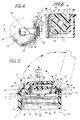
- the dispensing closure which is indicated generally at 10, comprises a cap base member 12 constructed as a unitary body by conventional injection molding techniques out of any one of a wide variety of known somewhat flexible, somewhat resilient, polymer materials.
- Various polyolefins such as polyethylene or polypropylene, may be effectively utilized.
- the cap base member 12 is defined by a depending cap skirt 14, which extends downwardly from a top surface 16.
- An annular recessed shoulder 15 is provided around the periphery of the top surface between the top surface and the skirt. From Fig. 5, it can be seen that the skirt 14 is provided with threads 18 formed on the interior surface 20 of the skirt 14 for securing the cap base member to the neck 22 of the container 24 illustrated in phantom in Figs. 1 to 3 and in Fig. 5.
- Other means may be utilized for securing the cap base member to the neck of a container.
- a nozzle-like boss 17 is provided on the top surface 16 around a dispensing opening 28 formed in the top surface and providing communiction with the interior of the associated container.
- first and second generally parallel and resilient upstanding walls 30, 32 are provided on top surface 16 of cap member 12.
- the first upstanding wall 30 extends upwardly from the top surface such that the exterior surface 34 of the first wall is substantially continuous with the exterior surface 36 of the skirt 14.
- the second upstanding wall 32 is spaced inwardly from the first wall as shown in Figs. 4 and 5.
- the first upstanding wall 30 terminates above the top surfaces in a slightly curvilinear first enlarged portion 38, which tapers inwardly and downwardly to an integral curved interior surface 40.
- the second upstanding wall 32 similarly terminates above the top surface in second enlarged portion 42, which tapers inwardly and downwardly to merge with the second integral curved interior surface 44, the second enlarged portion 42 being greater in size than first enlarged portion 38.
- the first and second curved interior surfaces 40 and 44 are connected by means of a bottom surface 46. As best depicted in Fig. 5, the respective enlarged portions 38 and 42 of the interior surfaces are substantially in alignment with each other with respect to their position above the top surface.
- the walls 30, 32 have side edges 45, and form between them a longitudinal cylindrical cavity 48 characterized by a relatively narrow top opening 50 at the location of the enlarged portions.
- the dispensing closure of the present invention further comprises a cap lid member 54, adapted to be formed by conventional injection molding techniques.
- the cap lid member is defined by a generally planar top 56, which is integral with the top edge of an annular wall 58.
- the bottom edge of the annular wall is, in turn, integral with an annular shoulder 60, which merges with a depending lid skirt 62.
- the lid skirt is formed with a slot defined by opposing generally parallel side walls 66, and an upstanding vertical rear wall 68, the slot being open at the side adjacent to the lid skirt 62.
- the hinge post 70 of generally circular cross-sectional configuration extends between the side walls 66 of the slot 64.
- the hinge post 70 is disposed within the slot, inwardly of the exterior surface 72 of the lid skirt and generally parallel to the rear wall 68 of the slot.
- the cap lid member is adapted to be assembled to the cap base member by causing the hinge post 70 to be pushed downwardly into the cavity 48 through the narrow top opening 50, thereby causing the resilient upstanding walls to deflect outwardly so that the hinge post is able to enter the cavity.
- the hinge post Once the hinge post has passed beyond the enlarged portions of the deflected walls, and has been fully inserted into the cavity, the hinge post is securely and snugly maintained in the cylindrical cavity by frictional retention with the upstanding walls which, after the hinge post has been fully inserted into the bottom part of the cavity, are restored to their original position.
- the side walls defining the slot are in abutting relationship with the side edges of the upstanding posts.
- the relatively narrow top opening 50 defined between the enlarged portions of the cavity is designed to be smaller than the cross-section of the hinge post and, hence, prevents unwanted removal of the hinge post from the cavity and undesired or inadvertent separation of the cap lid member from the cap base member, but the bottom part of the cavity allows the hinge post to rotate therein about the horizontal axis of the hinge post 70.
- cap lid member from the cap base member by application of a pulling force to the respective members sufficient to cause outward deflection of the upstanding walls on the cap base member.
- the cap lid member is adapted to assume a closed position wherein the cap lid member is oriented horizontally with respect to the cap base member as is most clearly shown in Figs. 2 and 5.
- the latter position is characterised by the lower peripheral edge 74 of the lid skirt 62 resting upon the recessed shoulder 15 of the cap base member.
- a concentric sealing plug member 76 extends downwardly from the bottom surface of the planar top 56 of the cap lid member and, in the closed position of the cap lid member is received within the dispensing opening 28 formed in the cap base member so as to close off and seal the associated container and to prevent removal of the container contents.
- the sealing plug is preferably tightly received within the dispensing opening so as to provide some resistance to withdrawal from the dispensing opening.
- a tight, well-fitting relationship between the latter components insures against inadvertent opening of the dispensing closure and provides a degree of child resistance, in that the force required to be exerted on the cap lid member in order to remove the sealing plug from the opening is in excess of the force which is capable of being applied by a child.
- the closed position of the cap lid member is further characterised by the exterior surface of the lid skirt 62 being substantially continuous with the exterior surface of the cap skirt 14 so as to together define a smooth peripheral surface for the dispensing closure.
- This continuity may be interrupted, however, by a projecting lip 78 provided on the lid skirt preferably directly opposite the hinge post.
- the lip 78 extends slightly beyond the exterior surface of the cap skirt, thus providing a means whereby the cap lid member may be grasped by the user for movement to an open position,
- the cap lid member is intended to assume an open position by a user manually pushing or pulling the cap lid member upwardly with respect to the cap base member with sufficient force to withdraw the sealing plug from the dispensing opening 28 and to cause rotation of the cap lid member with respect to the cap base member around the hinge post.
- Rotation of the cap lid member in a first direction to the fully open position which is illustrated in Fig. 3 and in phantom in Fig. 5, results in rotation of the hinge post within the cavity 48.
- the fully open position of the dispensing closure presents the dispensing opening in an unobstructed manner, whereupon the contents of the associated container may be dispensed therefrom by pouring, squeezing, or the like.
- the latter types of dispensing operations are isolated from interference by the cap lid member, due to the fact that the cap lid member, having been caused to assume a fully open position, is adapted to remain in such position until such time as it is further acted upon by the user.
- the cap lid member is maintained in the open position because the enlarged portions, and the upstanding walls of the cap base member, prohibit rotation of the hinge post and, hence, the cap lid member, in absence of a manual force directed against the cap lid member to cause rotation of the lid member.
- the hinge post is rotated within the cavity until the fully closed position for the cap lid member is achieved by further downward movement of the cap lid member to cause the sealing plug to be inserted into the dispensing opening.
- the cap lid member 54 of the present invention is further characterized by a recessed flat portion 80 formed in the planar top 56.
- the recessed portion is bounded by integrally formed paralled side walls 82, which are joined by a rear wall 84 and a front wall 86.
- the side, rear and front walls integrally connect the recessed portion 80 to the planar top 56, as clearly shown in Fig. 6.
- the exterior surface 88 of the front wall is downwardly curved, merging with the annular wall 58 and the rear wall 68 of the slot 64 formed in the cap lid member.
- the side, rear and front walls of the recessed portion define an elongated groove 90 in the planar top of the cap lid member.
- a vertically directed cylindrical opening 92 extends through the recessed portion proximate the rear wall 84. This opening is generally coaxial with the sealing plug 76, leading into the interior of the sealing plug and, hence, establishing communication with the interior of the container.
- the opening 92 is smaller in cross-sectional area than the dispensing opening 28.
- aligned bearing cavities 94 are located in the side walls 82 so as to face each other. These bearing cavities have a common horizontally extending axis (not shown) which is located so as to intersect the vertically extending axis (not shown) of the opening 92. This horizontal axis is parallel to the axis of the hinge post 70.
- the elongated groove 90 is adapted to receive therein a spout member 96 in the form of an elongated member having a longitudinal passage 98 extending between a first end 100 and a second end 102.
- Cylindrical trunnions 104 are located adjacent the first end of the spout and are received within the aligned bearing cavities 94 to rotatably mount the spout member within the groove 90.
- the spout member is adapted to assume a closed position with respect to the cap lid member, wherein the top of the spout member lies generally flush with the planar top 56 of the cap lid member.
- the first end of the spout member, as illustreated in Figs. 5 and 6, is further characterized by a cylindrical portion 106 which, in the closed position of the spout member, fits against the opening 92 so as to close off and seal the interior of the associated container.
- An extension 108 is provided on the second end of the spout member and, in the closed position of the spout member, rests against and extends slightly beyond the exterior surface 88 of the curved front wall 86 of the elongated groove.
- the extension serves to allow the second end of the spout member to be grasped by the user for purposes of rotating the spout to the open and closed positions.
- Rotation of the spout member to a vertical open position corresponds to alignment of the longitudinal passage 98 in the spout member with the opening formed in the recessed portion of the cap lid member.
- the cap lid member When the cap lid member is in its closed position, the contents of the container may thus be dispensed through the aligned passage and opening 92.
- the cap lid member When the cap lid member is rotated upwardly in a first direction to an open position about the hinge post to present the relatively large dispensing opening 28, the contents of the container are able to be released with relative freedom, such as that associated with a pouring action.
- the cap lid member When, however, the cap lid member is in a closed position, and only the spout member is caused to assume an open position by upward rotation in a second direction opposite to the first direction, the contents of the container are able to be dispensed through the much more constricted passage 98. The more constricted passage affords a more controlled release of the container contents.
- the dispensing closure is ideally suited for implementation with a container for liquid laundry detergent, wherein the larger dispensing closure may be utilized to pour the detergent into a measuring cup or into the washing machine, and the smaller dispensing closure may be selectively employed for dispensing small amounts of liquid detergent directly onto particular soiled or spotted areas on items of clothing or the like.
Landscapes
- Engineering & Computer Science (AREA)
- Mechanical Engineering (AREA)
- Closures For Containers (AREA)
- Containers And Packaging Bodies Having A Special Means To Remove Contents (AREA)
- Beans For Foods Or Fodder (AREA)
Claims (13)
- Abgabeverschluß mit einem Kappenbasisteil (12), das mit einem Behälter (24) mit Inhalt verbindbar ist, mit einer in dem Kappenbasisteil ausgebildeten ersten Abgabeöffnung (28), mit einem Kappendeckelteil (54), mit einer Einrichtung (66) zum Befestigen des Kappendeckelteils am Kappenbasisteil derart, daß das Dekkelteil eine Schließstellung einnehmen kann, in der die erste Öffnung abgedichtet ist und aus der es um eine erste Achse (70) aufwärts in eine Öffnungsstellung verschwenkbar ist, in der die erste Öffnung (28) unversperrt ist, so daß der Inhalt des Behälters durch die erste Öffnung abgegeben werden kann, mit einer zweiten Abgabeöffnung (92), die im Kappendeckenteil ausgebildet ist und im wesentlichen mit der ersten Öffnung fluchtet, wenn sich das Deckelteil in seiner Schließstellung befindet, wobei die zweite Abgabeöffnung (92) eine kleinere Querschnittsfläche als die erste Öffnung (28) aufweist, mit einer im Kappendeckelteil ausgebildeten länglichen Aussparung (90), mit einem verschwenkbaren Tüllenteil (96), das um eine zweite Achse (104) in der länglichen Aussparung verschwenkbar angebracht ist, und mit einem in der Tülle ausgebildeten längs verlaufenden Abgabedurchlaß (98), wobei das Tüllenteil eine Schließstellung einnehmen kann, in der es die zweite Abgabeöffnung verschließt, und wobei es aus der Schließstellung in eine Öffnungsstellung aufwärts verschwenkbar ist, in der der Längsdurchlaß (98) und die zweite Abgabeöffnung miteinander fluchten derart, daß der Inhalt des Behälters, wenn sich das Kappendeckelteil in seiner Schließstellung befindet, durch die miteinander fluchtende zweite Abgabeöffnung und den Längsdurchlaß abgegeben werden kann, wobei die zweite Achse parallel zur ersten Achse verläuft derart, daß das Tüllenteil aus seiner Schließstellung in seine Öffnungsstellung in einer Schwenkrichtung aufwärts verschwenkbar ist, die der Schwenkrichtung entgegengesetzt ist, in der das Kappenteil aus seiner Schließstellung in seine Öffnungsstellung aufwärts verschwenkbar ist.
- Abgabeverschluß nach Anspruch 1, dadurch gekennzeichnet, daß die Querschnittsfläche des Längsdurchlasses (98) kleiner ist als die Querschnittsfläche der ersten Abgabeöffnung (28).
- Abgabeverschluß nach Anspruch 1 und 2, bei dem das Kappenbasisteil durch eine obere Fläche (16) und einem nach unten gerichteten Kappenmantel (14) definiert und das Kappendeckelteil durch ein ebenes Oberteil (56) und einem nach unten gerichteten Deckelmantel (62) definiert ist.
- Abgabeverschluß nach einem der Ansprüche 1 bis 3, gekennzeichnet durch einen Dichtungsstopfen (76), der sich von einem Oberteil (56) des Kappendeckenteils nach unten erstreckt, wobei der Dichtungsstopfen, wenn sich das Kappendeckelteil in der Schließstellung befindet, innerhalb der ersten Abgabeöffnung (28) dicht eingreift.
- Abgabeverschluß nach einem der Ansprüche 1 bis 4, dadurch gekennzeichnet, daß das Kappendeckelteil einen Scharnierzapfen (70) und das Kappenbasisteil aufrecht stehende Wandteile (30, 32) aufweisen, die zwischen sich eine Aushöhlung (48) mit einer Einführungsöffnung definieren, die enger als die Dicke des Scharnierzapfens ist und in die der Gelenkzapfen durch elastisches Deformieren der Wandteile (30, 32) eingedrückt werden kann.
- Abgabeverschluß nach einem der Ansprüche 1 bis 4, bei dem das Kappenbasisteil eine erste und eine zweite elastische, aufrecht stehende Wand (30, 32) aufweist, die an seiner oberen Fläche (16) vorgesehen sind und in vergrößerten Abschnitten (38, 42) enden, wobei jede Wand gegenüberliegende Seitenkanten (45) aufweist, eine im allgemeinen zylindrische Aushöhlung (48) zwischen der ersten und der zweiten Wand ausgebildet ist, das Kappendeckelteil einen nach unten gerichteten, mit einer Aussparung (64) ausgebildeten Deckelmantel aufweist, ein Scharnierzapfen (70) sich quer durch die Aussparung erstreckt und innerhalb der Aushöhlung (48) aufnehmbar ist und wobei der Scharnierzapfen in der Aushöhlung drehbar und darin mittels der vergrößerten Abschnitte und durch reibschlüssigen Eingriff mit den aufrecht stehenden Wänden zurückgehalten ist.
- Abgabeverschluß nach Anspruch 6, bei dem die im Deckelmantel ausgebildete Aussparung (64) durch ein Paar Seitenwände (66) und eine Rückwand (68) definiert ist und bei dem die Seitenkanten (45) der Wände (30, 32) in einer im allgemeinen mit den Seitenwänden (66) aneinander anstoßenden Beziehung die Aussparung (64) definieren, sobald wenn Scharnierzapfen (70) innerhalb der Aushöhlung aufgenommen ist.
- Abgabeverschluß nach einem der Ansprüche 5 bis 7, bei dem das Kappendeckelteil in seiner Öffnungsstellung mittels der aufrecht stehenden Wände (30, 32) festhaltbar ist.
- Abgabeverschluß nach einem der Ansprüche 5 bis 8, bei dem die Außenfläche der ersten aufrecht stehenden Wand (30) mit der Außenfläche (36) des Kappenbasisteils fluchtet.
- Abgabeverschluß nach einem der Ansprüche 1 bis 9, bei dem das Kappenbasisteil einen Mantel (14) mit einer Außenfläche (36) aufweist, die, wenn sich das Kappendeckelteil in der Schließstellung befindet, mit der Außenfläche eines Mantels (62) des Deckelteils im wesentlichen fluchtet.
- Abgabeverschluß nach einem der Ansprüche 1 bis 10, bei dem die längliche Aussparung (90) im Deckelteil durch ein Paar Seitenwände (82), eine Rückwand (84) und eine Vorderwand (86) definiert ist, wobei die Seitenwände Lagerausnehmungen (94) definieren und das Tüllenteil ein Paar Drehzapfen (104) aufweist, die drehbar in den Lagerausnehmungen aufgenommen sind.
- Abgabeverschluß nach Anspruch 11, bei dem die Frontwand (86) der Längsvertiefung mit einem ebenen Oberteil (56) des Kappendeckelteils über eine konkav gekrümmte Wand (88) verbunden ist.
- Abgabeverschluß nach Anspruch 12, bei dem das Außenende (108) des Tüllenteils, wenn sich das Tüllenteil in der Schließstellung befindet, über die gekrümmte Wand (88) vorsteht.
Priority Applications (1)
| Application Number | Priority Date | Filing Date | Title |
|---|---|---|---|
| AT89310733T ATE89522T1 (de) | 1988-10-19 | 1989-10-18 | Ausgabeverschluss. |
Applications Claiming Priority (2)
| Application Number | Priority Date | Filing Date | Title |
|---|---|---|---|
| US259598 | 1988-10-19 | ||
| US07/259,598 US4903870A (en) | 1988-10-19 | 1988-10-19 | Dispensing closure |
Publications (3)
| Publication Number | Publication Date |
|---|---|
| EP0365316A2 EP0365316A2 (de) | 1990-04-25 |
| EP0365316A3 EP0365316A3 (en) | 1990-10-24 |
| EP0365316B1 true EP0365316B1 (de) | 1993-05-19 |
Family
ID=22985585
Family Applications (1)
| Application Number | Title | Priority Date | Filing Date |
|---|---|---|---|
| EP89310733A Expired - Lifetime EP0365316B1 (de) | 1988-10-19 | 1989-10-18 | Ausgabeverschluss |
Country Status (6)
| Country | Link |
|---|---|
| US (1) | US4903870A (de) |
| EP (1) | EP0365316B1 (de) |
| AT (1) | ATE89522T1 (de) |
| CA (1) | CA2000912C (de) |
| DE (1) | DE68906636T2 (de) |
| ES (1) | ES2040469T3 (de) |
Families Citing this family (34)
| Publication number | Priority date | Publication date | Assignee | Title |
|---|---|---|---|---|
| US5730322A (en) * | 1995-12-26 | 1998-03-24 | Allergan | Multiple flow volume dispensing cap |
| US5868283A (en) * | 1996-07-02 | 1999-02-09 | Lever Brothers Company, Division Of Conopco, Inc. | Reclosable closure and bottle |
| USD408288S (en) * | 1996-12-19 | 1999-04-20 | Lever Brothers Company, | Combined bottle and cap |
| US5961010A (en) * | 1997-01-09 | 1999-10-05 | Erie Country Plastics Corporation | Dispensing beverage closure |
| US5873478A (en) * | 1997-01-13 | 1999-02-23 | Sullivan; Michael J. | Spill-proof cap for beverage containers |
| AU689754B3 (en) * | 1997-12-02 | 1998-04-02 | Wang Wen-Pin | Cap assembly having a sucking member for a bottle |
| US5927535A (en) * | 1998-02-26 | 1999-07-27 | Top Seal Corporation | Tablet dispensing closure for containers |
| USD412265S (en) * | 1998-08-17 | 1999-07-27 | Hall Jr Charles E | Container lid having a double-pour spout |
| US6325075B1 (en) * | 1999-11-12 | 2001-12-04 | Topline Products Company, Inc. | Device for applying glitter particles |
| US6976611B2 (en) * | 2000-11-27 | 2005-12-20 | Jung Min Lee | Pressure dispensing cap for liquid container |
| US6382476B1 (en) * | 2001-05-30 | 2002-05-07 | Seaquist Closures Foreign, Inc. | Single axis dual dispensing closure |
| US7021481B2 (en) * | 2001-06-01 | 2006-04-04 | The Coca-Cola Company | Container lid with multiple openings |
| NO20020277D0 (no) * | 2002-01-18 | 2002-01-18 | Svein Myhre | Fremgangsmåte ved tilveiebringelse av et hengslet garantilukke, hengslet garantilukke og beholder med hengsletgarantilukke |
| US7165695B2 (en) * | 2003-02-11 | 2007-01-23 | Primesource Building Products, Inc. | Dispensing container for dispensing fasteners |
| US20080029548A1 (en) * | 2006-05-05 | 2008-02-07 | Ann De Wree | Fabric treatment dispensing package |
| US10549289B2 (en) * | 2008-06-18 | 2020-02-04 | Silgan Dispensing Systems Slatersville, Llc | Fan orifice dispensing closure |
| JP5650508B2 (ja) * | 2010-11-25 | 2015-01-07 | 日本クロージャー株式会社 | 容器蓋 |
| US20120241454A1 (en) * | 2011-03-24 | 2012-09-27 | Dennis Stephen R | Multi-Stage Opening and Dispensing Closure |
| US20130025740A1 (en) * | 2011-07-28 | 2013-01-31 | Ruby Osten | Container for dispensing liquid |
| CN102756852B (zh) * | 2012-08-06 | 2014-07-16 | 上海洁诺德塑胶制品有限公司 | 液体调味罐 |
| US8672174B1 (en) * | 2013-01-11 | 2014-03-18 | Leedsworld, Inc. | Multi-function lid for beverage containers |
| US10173811B2 (en) * | 2014-06-18 | 2019-01-08 | Weatherchem Corporation | Dual hinge flip cap closure |
| CN109561772A (zh) | 2016-05-04 | 2019-04-02 | 哈迪·斯坦曼 | 便携式饮料容器 |
| USD808713S1 (en) | 2016-12-13 | 2018-01-30 | Yeti Coolers, Llc | Lid |
| USD812970S1 (en) | 2016-12-13 | 2018-03-20 | Yeti Coolers, Llc | Lid |
| USD821135S1 (en) | 2016-12-13 | 2018-06-26 | Yeti Coolers, Llc | Lid |
| USD821809S1 (en) | 2016-12-13 | 2018-07-03 | Yeti Coolers, Llc | Lid |
| USD811162S1 (en) | 2016-12-13 | 2018-02-27 | Yeti Coolers, Llc | Lid |
| US11365033B2 (en) | 2019-04-01 | 2022-06-21 | Global Advantage Trading and Imports, LLC | Apparatus and methods for dispensing beverages |
| US11358760B2 (en) | 2019-09-10 | 2022-06-14 | Helen Of Troy Limited | Straw lid assembly |
| US12452355B2 (en) | 2022-01-26 | 2025-10-21 | Scosche Industries, Inc. | Container magnetic device mount |
| US20230233006A1 (en) * | 2022-01-26 | 2023-07-27 | Scosche Industries, Inc. | Container magnetic device mount |
| USD1073440S1 (en) | 2023-06-09 | 2025-05-06 | Scosche Industries, Inc. | Container magnetic device mount |
| USD1111653S1 (en) * | 2025-01-13 | 2026-02-10 | Dewei Cheng | Lid |
Citations (4)
| Publication number | Priority date | Publication date | Assignee | Title |
|---|---|---|---|---|
| US365103A (en) * | 1887-06-21 | Beeghe | ||
| US3655099A (en) * | 1970-07-27 | 1972-04-11 | Polytop Corp | Rotatable spout closures with latch structures |
| US4209114A (en) * | 1977-12-22 | 1980-06-24 | Polytop Corporation | Dispensing closure structures |
| US4219138A (en) * | 1978-10-16 | 1980-08-26 | Polytop Corporation | Dispensing closure utilizing a sealing element supported by a washer spring |
Family Cites Families (18)
| Publication number | Priority date | Publication date | Assignee | Title |
|---|---|---|---|---|
| US1645829A (en) * | 1926-06-07 | 1927-10-18 | Homer A Sudds | Bottle-container closure |
| US1959874A (en) * | 1932-10-13 | 1934-05-22 | Clark Mfg Co J L | Container |
| US2006588A (en) * | 1934-07-09 | 1935-07-02 | Ehret Henrietta | Tobacco can |
| US2753051A (en) * | 1952-12-26 | 1956-07-03 | Earl S Tupper | Hinged and swivellable seal and strainer |
| US2800259A (en) * | 1955-12-27 | 1957-07-23 | Poleete Inc | Container structures |
| US2971664A (en) * | 1959-02-17 | 1961-02-14 | Aladdin Ind Inc | Draw-through stopper for vacuum bottles or the like |
| US3180541A (en) * | 1960-01-04 | 1965-04-27 | Rexall Drug Chemical | Pitcher and cover |
| US3465925A (en) * | 1967-02-01 | 1969-09-09 | Francesco Bertolli Spa | Combined plastic closure and pouring spout |
| US3477618A (en) * | 1968-06-10 | 1969-11-11 | Polytop Corp | Dispensing closure |
| US3873006A (en) * | 1973-11-15 | 1975-03-25 | Mack Robert Fields | Safety secondary closure |
| US4282991A (en) * | 1979-10-02 | 1981-08-11 | Polytop Corporation | Dispensing closure seals |
| US4397400A (en) * | 1982-03-08 | 1983-08-09 | The Continental Group, Inc. | Nondetachable resealable closure |
| US4666068A (en) * | 1984-10-25 | 1987-05-19 | Sunbeam Plastics Corporation | Two piece dispensing closure |
| US4717050A (en) * | 1986-05-19 | 1988-01-05 | Sunbeam Plastics Corporation | Multiple orifice dispensing closure |
| US4682702A (en) * | 1986-06-27 | 1987-07-28 | Sunbeam Plastics Corporation | Tamper indicating closure |
| US4711372A (en) * | 1987-02-02 | 1987-12-08 | Sunbeam Plastics Corporation | Tamper indicating closure |
| US4778071A (en) * | 1988-02-16 | 1988-10-18 | Owens-Illinois Closure Inc. | Closure with snap type hinge |
| US4832219A (en) * | 1988-06-16 | 1989-05-23 | Owens-Illinois Closure Inc. | Dual dispensing hinged closure |
-
1988
- 1988-10-19 US US07/259,598 patent/US4903870A/en not_active Expired - Fee Related
-
1989
- 1989-10-18 DE DE8989310733T patent/DE68906636T2/de not_active Expired - Fee Related
- 1989-10-18 EP EP89310733A patent/EP0365316B1/de not_active Expired - Lifetime
- 1989-10-18 CA CA002000912A patent/CA2000912C/en not_active Expired - Fee Related
- 1989-10-18 AT AT89310733T patent/ATE89522T1/de not_active IP Right Cessation
- 1989-10-18 ES ES198989310733T patent/ES2040469T3/es not_active Expired - Lifetime
Patent Citations (4)
| Publication number | Priority date | Publication date | Assignee | Title |
|---|---|---|---|---|
| US365103A (en) * | 1887-06-21 | Beeghe | ||
| US3655099A (en) * | 1970-07-27 | 1972-04-11 | Polytop Corp | Rotatable spout closures with latch structures |
| US4209114A (en) * | 1977-12-22 | 1980-06-24 | Polytop Corporation | Dispensing closure structures |
| US4219138A (en) * | 1978-10-16 | 1980-08-26 | Polytop Corporation | Dispensing closure utilizing a sealing element supported by a washer spring |
Also Published As
| Publication number | Publication date |
|---|---|
| DE68906636T2 (de) | 1993-09-02 |
| CA2000912A1 (en) | 1990-04-18 |
| EP0365316A2 (de) | 1990-04-25 |
| ATE89522T1 (de) | 1993-06-15 |
| EP0365316A3 (en) | 1990-10-24 |
| US4903870A (en) | 1990-02-27 |
| ES2040469T3 (es) | 1993-10-16 |
| CA2000912C (en) | 1994-02-15 |
| DE68906636D1 (de) | 1993-06-24 |
Similar Documents
| Publication | Publication Date | Title |
|---|---|---|
| EP0365316B1 (de) | Ausgabeverschluss | |
| US4993606A (en) | Dispensing closure | |
| US5395015A (en) | Dispensing closure with a modified lid for increased opening angle | |
| CA1268142A (en) | Multiple orifice dispensing closure | |
| US5542585A (en) | Dispensing closure with pivotably mounted spout and means for limiting travel thereof | |
| US5251793A (en) | Dispensing closure | |
| EP0078322B1 (de) | Kappe mit abgabeverschluss | |
| US4793502A (en) | Hinged dispensing closure | |
| US6039224A (en) | Multiple-orifice dispensing system with improved seal | |
| US5065887A (en) | Container with hinged cover | |
| US4881668A (en) | Closure with open lid retainer | |
| US5975368A (en) | Bi-modal dispensing system for particulate material | |
| US4852770A (en) | Child-resistant dispensing closure | |
| US6158632A (en) | Closure with recessed hinged cover | |
| US4742928A (en) | Dispensing closure with articulated flip-top cap | |
| US4821899A (en) | Dispensing closure | |
| US4754898A (en) | Multi-orifice dispensing closure | |
| US4832219A (en) | Dual dispensing hinged closure | |
| CA2147997A1 (en) | Child resistant closure with recessed latch | |
| US4402435A (en) | Dispensing type cap closure | |
| EP0943039B1 (de) | Abgabevorrichtung | |
| US3556331A (en) | Safety closure for containers | |
| EP0618873B1 (de) | Kindersicherer verschluss mit schutzrand und geneigter oberen wand | |
| US4807781A (en) | Container and dispensing-closure assembly | |
| EP0404856B1 (de) | Abgabeverschluss |
Legal Events
| Date | Code | Title | Description |
|---|---|---|---|
| PUAI | Public reference made under article 153(3) epc to a published international application that has entered the european phase |
Free format text: ORIGINAL CODE: 0009012 |
|
| AK | Designated contracting states |
Kind code of ref document: A2 Designated state(s): AT BE CH DE ES FR GB GR IT LI LU NL SE |
|
| PUAL | Search report despatched |
Free format text: ORIGINAL CODE: 0009013 |
|
| AK | Designated contracting states |
Kind code of ref document: A3 Designated state(s): AT BE CH DE ES FR GB GR IT LI LU NL SE |
|
| RHK1 | Main classification (correction) |
Ipc: B65D 47/08 |
|
| 17P | Request for examination filed |
Effective date: 19910104 |
|
| 17Q | First examination report despatched |
Effective date: 19911018 |
|
| ITF | It: translation for a ep patent filed | ||
| GRAA | (expected) grant |
Free format text: ORIGINAL CODE: 0009210 |
|
| AK | Designated contracting states |
Kind code of ref document: B1 Designated state(s): AT BE CH DE ES FR GB GR IT LI LU NL SE |
|
| REF | Corresponds to: |
Ref document number: 89522 Country of ref document: AT Date of ref document: 19930615 Kind code of ref document: T |
|
| REF | Corresponds to: |
Ref document number: 68906636 Country of ref document: DE Date of ref document: 19930624 |
|
| ET | Fr: translation filed | ||
| REG | Reference to a national code |
Ref country code: GR Ref legal event code: FG4A Free format text: 3007924 |
|
| REG | Reference to a national code |
Ref country code: ES Ref legal event code: FG2A Ref document number: 2040469 Country of ref document: ES Kind code of ref document: T3 |
|
| PG25 | Lapsed in a contracting state [announced via postgrant information from national office to epo] |
Ref country code: LU Free format text: LAPSE BECAUSE OF NON-PAYMENT OF DUE FEES Effective date: 19931031 |
|
| PLBE | No opposition filed within time limit |
Free format text: ORIGINAL CODE: 0009261 |
|
| STAA | Information on the status of an ep patent application or granted ep patent |
Free format text: STATUS: NO OPPOSITION FILED WITHIN TIME LIMIT |
|
| 26N | No opposition filed | ||
| EAL | Se: european patent in force in sweden |
Ref document number: 89310733.4 |
|
| PGFP | Annual fee paid to national office [announced via postgrant information from national office to epo] |
Ref country code: SE Payment date: 19971017 Year of fee payment: 9 |
|
| PGFP | Annual fee paid to national office [announced via postgrant information from national office to epo] |
Ref country code: AT Payment date: 19981012 Year of fee payment: 10 |
|
| PG25 | Lapsed in a contracting state [announced via postgrant information from national office to epo] |
Ref country code: SE Free format text: LAPSE BECAUSE OF NON-PAYMENT OF DUE FEES Effective date: 19981019 |
|
| PGFP | Annual fee paid to national office [announced via postgrant information from national office to epo] |
Ref country code: NL Payment date: 19981031 Year of fee payment: 10 |
|
| EUG | Se: european patent has lapsed |
Ref document number: 89310733.4 |
|
| PGFP | Annual fee paid to national office [announced via postgrant information from national office to epo] |
Ref country code: FR Payment date: 19990817 Year of fee payment: 11 |
|
| PGFP | Annual fee paid to national office [announced via postgrant information from national office to epo] |
Ref country code: GR Payment date: 19990930 Year of fee payment: 11 |
|
| PGFP | Annual fee paid to national office [announced via postgrant information from national office to epo] |
Ref country code: ES Payment date: 19991015 Year of fee payment: 11 |
|
| PG25 | Lapsed in a contracting state [announced via postgrant information from national office to epo] |
Ref country code: AT Free format text: LAPSE BECAUSE OF NON-PAYMENT OF DUE FEES Effective date: 19991018 |
|
| PGFP | Annual fee paid to national office [announced via postgrant information from national office to epo] |
Ref country code: CH Payment date: 19991021 Year of fee payment: 11 |
|
| PGFP | Annual fee paid to national office [announced via postgrant information from national office to epo] |
Ref country code: DE Payment date: 19991124 Year of fee payment: 11 |
|
| PGFP | Annual fee paid to national office [announced via postgrant information from national office to epo] |
Ref country code: BE Payment date: 19991203 Year of fee payment: 11 |
|
| PG25 | Lapsed in a contracting state [announced via postgrant information from national office to epo] |
Ref country code: NL Free format text: LAPSE BECAUSE OF NON-PAYMENT OF DUE FEES Effective date: 20000501 |
|
| NLV4 | Nl: lapsed or anulled due to non-payment of the annual fee |
Effective date: 20000501 |
|
| PGFP | Annual fee paid to national office [announced via postgrant information from national office to epo] |
Ref country code: GB Payment date: 20000914 Year of fee payment: 12 |
|
| PG25 | Lapsed in a contracting state [announced via postgrant information from national office to epo] |
Ref country code: ES Free format text: LAPSE BECAUSE OF NON-PAYMENT OF DUE FEES Effective date: 20001019 |
|
| PG25 | Lapsed in a contracting state [announced via postgrant information from national office to epo] |
Ref country code: LI Free format text: LAPSE BECAUSE OF NON-PAYMENT OF DUE FEES Effective date: 20001031 Ref country code: GR Free format text: LAPSE BECAUSE OF NON-PAYMENT OF DUE FEES Effective date: 20001031 Ref country code: CH Free format text: LAPSE BECAUSE OF NON-PAYMENT OF DUE FEES Effective date: 20001031 Ref country code: BE Free format text: LAPSE BECAUSE OF NON-PAYMENT OF DUE FEES Effective date: 20001031 |
|
| BERE | Be: lapsed |
Owner name: POLYTOP CORP. Effective date: 20001031 |
|
| REG | Reference to a national code |
Ref country code: CH Ref legal event code: PL |
|
| PG25 | Lapsed in a contracting state [announced via postgrant information from national office to epo] |
Ref country code: FR Free format text: LAPSE BECAUSE OF NON-PAYMENT OF DUE FEES Effective date: 20010629 |
|
| PG25 | Lapsed in a contracting state [announced via postgrant information from national office to epo] |
Ref country code: DE Free format text: LAPSE BECAUSE OF NON-PAYMENT OF DUE FEES Effective date: 20010703 |
|
| REG | Reference to a national code |
Ref country code: FR Ref legal event code: ST |
|
| PG25 | Lapsed in a contracting state [announced via postgrant information from national office to epo] |
Ref country code: GB Free format text: LAPSE BECAUSE OF NON-PAYMENT OF DUE FEES Effective date: 20011018 |
|
| REG | Reference to a national code |
Ref country code: GB Ref legal event code: IF02 |
|
| GBPC | Gb: european patent ceased through non-payment of renewal fee |
Effective date: 20011018 |
|
| REG | Reference to a national code |
Ref country code: ES Ref legal event code: FD2A Effective date: 20011113 |
|
| PG25 | Lapsed in a contracting state [announced via postgrant information from national office to epo] |
Ref country code: IT Free format text: LAPSE BECAUSE OF NON-PAYMENT OF DUE FEES Effective date: 20051018 |