EP0365317A1 - Dispositif de matrice à coussin élastique pneumatique - Google Patents
Dispositif de matrice à coussin élastique pneumatique Download PDFInfo
- Publication number
- EP0365317A1 EP0365317A1 EP89310734A EP89310734A EP0365317A1 EP 0365317 A1 EP0365317 A1 EP 0365317A1 EP 89310734 A EP89310734 A EP 89310734A EP 89310734 A EP89310734 A EP 89310734A EP 0365317 A1 EP0365317 A1 EP 0365317A1
- Authority
- EP
- European Patent Office
- Prior art keywords
- pressure
- capability
- valve
- die cushion
- shut
- Prior art date
- Legal status (The legal status is an assumption and is not a legal conclusion. Google has not performed a legal analysis and makes no representation as to the accuracy of the status listed.)
- Granted
Links
- 238000010586 diagram Methods 0.000 claims description 21
- 230000033001 locomotion Effects 0.000 claims description 13
- 230000001105 regulatory effect Effects 0.000 claims description 12
- 230000008859 change Effects 0.000 claims description 8
- 238000004891 communication Methods 0.000 claims description 4
- 238000004519 manufacturing process Methods 0.000 abstract description 27
- 238000005336 cracking Methods 0.000 description 18
- 239000000872 buffer Substances 0.000 description 11
- 230000007423 decrease Effects 0.000 description 11
- 239000000047 product Substances 0.000 description 11
- 230000000694 effects Effects 0.000 description 10
- 208000036366 Sensation of pressure Diseases 0.000 description 7
- 238000013016 damping Methods 0.000 description 5
- 239000000463 material Substances 0.000 description 5
- 238000013459 approach Methods 0.000 description 4
- 230000003247 decreasing effect Effects 0.000 description 4
- 238000000034 method Methods 0.000 description 3
- 230000008030 elimination Effects 0.000 description 2
- 238000003379 elimination reaction Methods 0.000 description 2
- 239000012464 large buffer Substances 0.000 description 2
- 230000009467 reduction Effects 0.000 description 2
- 238000012546 transfer Methods 0.000 description 2
- 230000004075 alteration Effects 0.000 description 1
- 230000001174 ascending effect Effects 0.000 description 1
- 239000007795 chemical reaction product Substances 0.000 description 1
- 230000000052 comparative effect Effects 0.000 description 1
- 238000010276 construction Methods 0.000 description 1
- 230000002950 deficient Effects 0.000 description 1
- 238000013461 design Methods 0.000 description 1
- 230000008569 process Effects 0.000 description 1
- 230000000630 rising effect Effects 0.000 description 1
Images




Classifications
-
- B—PERFORMING OPERATIONS; TRANSPORTING
- B30—PRESSES
- B30B—PRESSES IN GENERAL
- B30B15/00—Details of, or accessories for, presses; Auxiliary measures in connection with pressing
- B30B15/02—Dies; Inserts therefor; Mounting thereof; Moulds
-
- F—MECHANICAL ENGINEERING; LIGHTING; HEATING; WEAPONS; BLASTING
- F16—ENGINEERING ELEMENTS AND UNITS; GENERAL MEASURES FOR PRODUCING AND MAINTAINING EFFECTIVE FUNCTIONING OF MACHINES OR INSTALLATIONS; THERMAL INSULATION IN GENERAL
- F16F—SPRINGS; SHOCK-ABSORBERS; MEANS FOR DAMPING VIBRATION
- F16F9/00—Springs, vibration-dampers, shock-absorbers, or similarly-constructed movement-dampers using a fluid or the equivalent as damping medium
- F16F9/02—Springs, vibration-dampers, shock-absorbers, or similarly-constructed movement-dampers using a fluid or the equivalent as damping medium using gas only or vacuum
- F16F9/0209—Telescopic
-
- B—PERFORMING OPERATIONS; TRANSPORTING
- B21—MECHANICAL METAL-WORKING WITHOUT ESSENTIALLY REMOVING MATERIAL; PUNCHING METAL
- B21D—WORKING OR PROCESSING OF SHEET METAL OR METAL TUBES, RODS OR PROFILES WITHOUT ESSENTIALLY REMOVING MATERIAL; PUNCHING METAL
- B21D24/00—Special deep-drawing arrangements in, or in connection with, presses
- B21D24/02—Die-cushions
-
- F—MECHANICAL ENGINEERING; LIGHTING; HEATING; WEAPONS; BLASTING
- F16—ENGINEERING ELEMENTS AND UNITS; GENERAL MEASURES FOR PRODUCING AND MAINTAINING EFFECTIVE FUNCTIONING OF MACHINES OR INSTALLATIONS; THERMAL INSULATION IN GENERAL
- F16F—SPRINGS; SHOCK-ABSORBERS; MEANS FOR DAMPING VIBRATION
- F16F15/00—Suppression of vibrations in systems; Means or arrangements for avoiding or reducing out-of-balance forces, e.g. due to motion
- F16F15/02—Suppression of vibrations of non-rotating, e.g. reciprocating systems; Suppression of vibrations of rotating systems by use of members not moving with the rotating systems
- F16F15/023—Suppression of vibrations of non-rotating, e.g. reciprocating systems; Suppression of vibrations of rotating systems by use of members not moving with the rotating systems using fluid means
- F16F15/027—Suppression of vibrations of non-rotating, e.g. reciprocating systems; Suppression of vibrations of rotating systems by use of members not moving with the rotating systems using fluid means comprising control arrangements
-
- F—MECHANICAL ENGINEERING; LIGHTING; HEATING; WEAPONS; BLASTING
- F16—ENGINEERING ELEMENTS AND UNITS; GENERAL MEASURES FOR PRODUCING AND MAINTAINING EFFECTIVE FUNCTIONING OF MACHINES OR INSTALLATIONS; THERMAL INSULATION IN GENERAL
- F16F—SPRINGS; SHOCK-ABSORBERS; MEANS FOR DAMPING VIBRATION
- F16F9/00—Springs, vibration-dampers, shock-absorbers, or similarly-constructed movement-dampers using a fluid or the equivalent as damping medium
- F16F9/32—Details
- F16F9/44—Means on or in the damper for manual or non-automatic adjustment; such means combined with temperature correction
- F16F9/46—Means on or in the damper for manual or non-automatic adjustment; such means combined with temperature correction allowing control from a distance, i.e. location of means for control input being remote from site of valves, e.g. on damper external wall
Definitions
- the present invention relates to a pneumatic die cushion equipment.
- a pneumatic die cushion equipment of conventional type has an air cylinder, which is separated by a piston into an upper chamber and a lower chamber.
- the upper chamber is open to the atmosphere.
- a wear plate 4 is fixed on the upper end of a piston rod receives a cushion pin (not shown).
- a buffer tank communicates with the lower chamber through a connection pipe.
- the pressure in the upper chamber is equal to atmospheric pressure and is thus constant. Consequently, the die cushion capability is the product of the pressure in the lower chamber and the sectional area of the piston.
- the pressure in the lower chamber increase when the piston moves down, i.e. when the volume of the lower chamber is decreased, the die cushion capability increases.
- die cushion capability i.e. the proper blank holding pressure necessary for press fabrication is determined by the quality of the material, and is inappropriate for the capability to increase too much.
- the buffer tank which has a volume 5 - 8 times as large as the volume of the cylinder. This hinders the extreme increase of the die cushion capability by enlarging the apparent volume of the lower chamber. This will be emphasized in more detail below.
- the object of the present invention is to offer a small and compact pneumatic die cushion equipment with simple structure, easy maneuverability and low cost, which can eliminate the large capacity buffer tank, the large-size compressor, the quick-acting large-size exhaust valve, etc., and can maintain the die cushion capability at constant level.
- the equipment according to the present invention consists of a closed type cylinder unit, which is to replace the open-to-atmosphere type cylinder of the conventional equipment.
- the new equipment is also based on the principle that the die cushion capability by the closed type cylinder is determined by the differential pressure between the lower chamber pressure and the upper chamber pressure, and the differential pressure is controlled by communicating the lower and upper chambers with each other.
- the lower chamber and the upper chamber having the cylinder of the piston there-between are communicated with each other through a check valve, which is opened when the differential pressure between the lower chamber pressure and the upper chamber pressure, changing with the downward movement of the piston, exceeds the preset value. Also, both chambers are communicated with each other through a shut-off valve, which hinders the excessive increase of the upper chamber pressure when the piston goes up.
- the lower chamber pressure increases and the differential pressure between the lower chamber pressure and the upper chamber pressure rapidly increases as the piston goes down from the upper limit due to the loading, and the die cushion capability corresponding to the preset differential pressure value is established.
- the check valve is opened, and the upper and the lower chambers are communicated with each other. Consequently, the lower chamber pressure is decreased, and the differential pressure is decreased to less than the preset value. At the same time, the check valve is closed.
- the equipment according to the present invention is of such structure that, the upper and lower chambers of the cylinder are communicated with other through a check valve, that the check valve is opened when the differential pressure between two chambers reaches the preset differential pressure value, and that the excessive increase of the upper chamber pressure is hindered by the shut-off valve when the piston goes up.
- the invention offers a small and compact pneumatic die cushion equipment, which can eliminate the large-size buffer tank, the high-pressure large-capacity compressor, the large-size quick-acting exhaust valve, etc. and which can maintain the die cushion capability at constant level and on low operating cost.
- Another object of this invention is to offer a pneumatic die cushion equipment, by which it is possible to change and adjust the die cushion capability during press fabrication.
- the equipment according to the present invention consists of a closed type cylinder unit, which is to replace the open-to-atmosphere type cylinder of the conventional equipment.
- the die cushion capability by the closed type cylinder is determined by the differential pressure between the lower chamber pressure and the upper chamber pressure, it is possible according to this equipment to adjust the die cushion capability through the control of differential pressure during the press fabrication by communicating the lower and the upper chambers with each other.
- the equipment according to this invention is characterized in that the lower and the upper chambers having a piston of the cylinder therebetween are communicated with each other through a first air passage equipped with a first shut-off valve and a second air passage equipped with a second shut-off valve, said first shut-off valve is constructed in such manner that it is opened when the differential pressure between the lower chamber pressure and the upper chamber pressure exceeds the preset differential pressure value inputted by the differential pressure setting means, a control means is provided to control the opening and the closing of said second shut-off valve when the piston goes up, a capability memorizing means to memorize two or more capability diagrams and a selection means to select one of the capability diagrams memorized by this capability memorizing means, and the die cushion capability can be changed and adjusted during press fabrication by changing the preset differential pressure value outputted by the differential pressure setting means according to the capability diagram selected by the selection means.
- the differential pressure setting means if the preset differential pressure value outputted by the differential pressure setting means is constant, the lower chamber pressure increases when the piston goes down from the upper limit due to the loading. Then, the differential pressure between the lower chamber pressure and the upper chamber pressure quickly increases, and the die cushion capability corresponding to the preset differential pressure value is thus established.
- the first shut-off valve serving as a check valve is opened, and the lower and the upper chambers are communicated with each other. Consequently, the lower chamber pressure is reduced, and the differential pressure goes down to below the preset differential pressure value. At the same time, the first shut-off valve is closed.
- the opening and the closing of the first shut-off valve are repeated as the piston goes down, and the differential pressure between two chambers is changed within the narrow range of the tolerance of the necessary blank holding pressure.
- the die cushion capability can be substantially maintained at the constant level until the piston reaches the lower limit.
- the preset differential pressure value inputted to the first shut-off valve by the differential pressure setting means corresponds to the capability diagram. Therefore, if the capability diagram is prepared in advance to "gradual increase”, “gradual decrease”, “stepwise increase or decrease”, etc. for the press fabrication, the die cushion capability can be automatically changed and adjusted during the press fabrication.
- the equipment by this invention is constructed in such manner that the upper and the lower chambers of the cylinder are communicated with each other through the first and the second air passages, that the die cushion capability is adjusted through the control of differential pressure by the first shut-off valve, and that the second shut-off valve is properly controlled when the piston goes up.
- the equipment by this invention can be designed in small and compact form, and it can eliminate the large-size buffer tank, the high-pressure large-capacity compressor, the quick-acting large-size exhaust valve, etc. of the conventional type equipment. With low operating cost, the equipment can attain the proper die cushion capability accurately and quickly.
- the differential pressure is controlled according to the capability diagram memorized by the capability memorizing means. This makes it possible to change and adjust the die cushion capability during the press fabrication to suit the product to be fabricated, and this contributes to the production of a wide variety of the high quality products at higher efficiency.
- 1 refers to a cylinder, 1U an upper chamber, 1L a lower chamber, 2 a piston, 10 a first air passage, 11 a pipe, 20 a first shut-off valve, 21 a pipe, 30 a first air passage, 31 a pipe, 40 a first shut-off valve, 41 a main unit, 50 a second air passage, 51 a second shut-off valve, 60 and 70 a pressure regulating valve and a control unit respectively to form the differential pressure setting means, 71 a means to generate the capability signal, 72 a capability memorizing means, 73 a selection means, 74 a standard capability setter, 75 and 76 a controller and a pressure setter respectively to form the control means, and 77 and 78 a controller and a pressure setter respectively to form the initial pressure setting means.
- Fig. 1 is a general schematical view of an embodiment of this invention
- Fig. 2 is a diagram to explain the operation of the equipment.
- the same number or symbol is used to the same component as that of the Fig. 7, which is given to illustrate a die cushion equipment of the conventional type, in order to simplify or omit the explanations.
- the die cushion equipment of the first embodiment of this invention consists of a cylinder unit (cylinder 1 and piston 2), a check valve 10, a shut-off valve 20, etc.
- the compressed air is supplied from the air source 15 comprising a small compressor, a pressure regulating valve 16 and a check valve 17.
- the air source 15 comprising a small compressor, a pressure regulating valve 16 and a check valve 17.
- the initial pressure PlS is established in the lower chamber 1L, which is formed below the piston 2 of the cylinder 1.
- This initial pressure PlS is set by the pressure regulating valve 16.
- the movable stroke (ST) of the piston 2 is between the upper limit UL and the lower limit LL in the cylinder 1.
- 1U represents the upper chamber formed above the piston 2.
- the die cushion capability of this equipment consisting of a closed cylinder unit is determined by the differential pressure between the lower chamber pressure Pl and the upper chamber pressure Pl if the sectional area A2 of the piston rod 3 is neglected.
- the check valve is installed in the middle of the pipe 11, connecting two chambers 1L and 1U.
- the check valve 10 of this embodiment is constructed in such manner that the die cushion capability corresponding to the proper blank holding pressure can be changed and adjusted.
- the check valve 10 is opened when the differential value reaches the preset value ⁇ S (e.g. 2.8 kgf/cm2, 3.0 kgf/cm2, 3.2 kgf/cm2, ##).
- ⁇ S preset value
- the shut-off valve 20 is installed in the middle of the pipe 21, connecting the upper chamber 1U and the lower chamber 1L, and it is a means to communicate the upper chamber 1U with the lower chamber 1L at appropriate time. In other words, it prevents the excessive increase of the upper chamber pressure Pu when the piston 2 goes up. It is closed when the piston 2 goes down, and it is opened at appropriate time when the piston goes up.
- the excessive increase of the pressur as mentioned in the present invention is defined as the increase of the upper chamber pressure Pu to the value higher than the lower chamber pressure Pl or as the increase of the upper chamber pressure Pu to the value, at which the piston 2 is no more capable to go up if the sectional area A2 of the piston rod 3 is taken into account.
- the control means 22 of this embodiment is constructed in such manner that the opening signal is issued to the shut-off valve 20 when the piston 2 goes up from the lower limit LL with the lower chamber pressure Pl reduced and the upper chamber pressure Pu increased and the pressures in two chambers Pl and Pu become equal to each other (with the lower chamber pressure Pl slightly higher), and that the closing signal is issued immediately before the piston 2 reaches the upper limit UL.
- the time to issue the opening signal can be determined by the ascending speed of the piston 2, and the signal may be issued at any point of the stroke (ST). It is also desirable to set the timing for the closing signal in such manner that the better upper limit damping effect can be obtained until the piston 2 can reach the upper limit UL.
- timing can be defined by the present position of the piston 2 (piston rod 3) detected by a position detector (not shown). However, the timing may be defined by detecting the differential pressure between the lower chamber pressure Pl and the upper chamber pressure Pu or by detecting the axial angle of the crank.
- the shut-off valve 20 and the control means 22 are not limited to the structures as described above.
- a pilot check valve may be provided to directly connect the upper chamber 1U with the lower chamber 1L, and the pipe 21 and the like may be omitted.
- 19 represents an exhaust valve to move the cushion downward.
- the upper chamber pressure Pl is supposed to be equal to the lower chamber pressure Pu at the upper limit UL in this embodiment, the upward movement, i.e. the differential pressure ⁇ is based on the effective area difference due to the presence of the sectional area A2 of the piston rod 3.
- the upper chamber 1U is opened to the atmospheric air. Accordingly, the die cushion capability gradually increases as shown by one-dot chain line of Fig. 2 and reaches Fpe at the lower limit LL. Thus, the predetermined die cushion capability Fp cannot be maintained at constant level.
- the blank holding pressure becomes too high by 20 - 25% at the lower limit LL.
- the predetermined die cushion capability can be quickly obtained because lower chamber pressure Pl is increased and the differential pressure ⁇ from the upper chamber pressure Pu is increased when the piston moves downward.
- the check valve 10 is opened, connecting two chambers 1L and 1U with each other.
- the lower chamber pressure Pl decreases and the upper chamber pressure Pu increases.
- the differential pressure 4 becomes smaller than lthe preset differential pressure ⁇ S, and the check valve 10 is closed again.
- the check valve 10 repeatedly performs the opening and closing operation according to the differential pressure 4 until the piston 2 reaches the lower limit LL.
- the die cushion capability F1 is controlled within the band with constant width even though there is slight change of differential pressure (as shown by the solid line zigzag in Fig. 2) according to the opening and closing operation of the check valve 10.
- the width of the band B is defined as the allowable range of the proper blank holding pressure.
- the width of the band B can be selected by setting the bore diameter, flow resistance, etc. of the check valve 10 and the pipe 11 against the volume of the cylinder 1 to appropriate values.
- the die cushion capability can be varied according to the preset differential pressure value ⁇ S of the differential pressure setter 12.
- the preset differential pressure value ⁇ S should be set to the value lower than that of the capability F1.
- the upward movement of the piston 2 from the lower limit LL depends upon the differential pressure ⁇ between the pressures Pl and Pu of two chambers and matches the upward movement of the slide in the initial stage. Then, it is performed smoothly in non-loaded status. As the lower chamber pressure Pl decreases and the upper chamber pressure Pu increases, the differential pressure ⁇ rapidly decreases.
- shut-off valve 20 is opened by the signal from the control means 22, and the two chambers 1U and 1L are connected with each other. Accordingly, the pressures Pl and Pu of two chambers become equal to each other, while the piston 2 moves further upward by the pushing force generated by the effective area difference due to the presence of the sectional area A2 of the piston rod 3.
- This piston may be left to go up to the upper limit UL, whereas the shut-off valve 20 is closed again in this embodiment immediately before the upper limit UL. Therefore, the upper chamber pressure Pu becomes slightly higher and rapidly reduces the pushing force of the piston 2. Thus, the better damping effect can be obtained at the upper limit UL.
- shut-off valve 20 is opened and closed again momentarily when the piston 2 closely approaches the upper limit UL.
- the lower chamber 1L and the upper chamber 1U are communicated with each other, and the communication is opned by the check valve 10 when the differential pressure between the pressures Pl and Pu of two chambers reaches the preset differential pressure ⁇ S. Accordingly, the differential pressure between the upper chamber pressure Pu and the lower pressure Pl can be kept at constant level, and the die cushion capability can be maintained at constant level during the press fabrication.
- this embodiment is based on a closed construction where the upper chamber 1U and the lower chamber 1L are connected with each other through the check valve 10, the pipe 11, the shut-off valve 20 and the pipe 21 and where the air in the lower chamber 1L is released into the upper chamber 1U when the piston 2 goes down.
- the die cushion capability can be adjusted by the cracking pressure (differential pressure) of the check valve 11, there is no need to install the high-pressure large-capacity compressor or the large-size exhaust valve as in the conventional equipment. This contributes to the compact design of the equipment and quick adjustment operation. Therefore, the production efficiency of the press can be raised with shorter waiting time. More economic operation can be achieved because there is no need to release large quantity of compressed air into the atmosphere.
- the upper chamber pressure Pu can be left unconsumed near the upper limit UL of the piston 2, i.e. residual pressure may be provided by setting the proper timing to close the shut-off valve 20. This is helpful to extensively decrease the impact force at the upper limit UL.
- the cracking pressure of the check valve 11 can be easily set and changed by the differential pressure setter 12, the necessary blank holding pressure can be quickly and accurately obtained. More strictlyover, the inconveniences such as the folds or damage of the flange can be avoided because the blank holding pressure remains constant regardless of the downward movement of the piston 2. This contributes to the stable production of high-quality products.
- shut-off valve 20 is so constructed that its opening and closing are controlled properly by the control means 22, the return speed of the piston 2 to the upper limit UL, the upper limit damping effect, etc. can be set to the values as desired.
- the embodiment 2 is constructed in such manner that the check valves 10 (10A, 10B and 10C) are installed in parallel as shown in Fig. 3, and that one check valve can be selected by the selection means 14 through changeover of the changeover switches 13 (13A, 13B and 13C) consisting of the corresponding electromagnetic valves.
- the changeover switches 13 13A, 13B and 13C
- this embodiment it is possible by this embodiment to obtain the same operation and effect as the embodiment 1, to set the die cushion capability more accurately because the cracking pressure of the check valve 11 is constant, and to perform the setting changeover more quickly because the changeover is carried out by simply opening or closing the changeover valve.
- the embodiments 1 and 2 above consist of a complete closed type cylinder unit (cylinder 1 and piston 2), whereas an opening valve 25 may be provided to open the upper chamber 1U to atmospheric air at proper time and temporarily as shown in Fig. 3 by two-dot chain line.
- an opening valve 25 may be provided to open the upper chamber 1U to atmospheric air at proper time and temporarily as shown in Fig. 3 by two-dot chain line.
- the die cushion capability is changeable and adjustable during press fabrication in the embodiment 3.
- this die cushion equipment comprises a cylinder unit consisting of a cylinder 1, a piston 2, etc., an initial pressure setting means, a differential pressure setting means, a capability memorizing means 72, a selection means 73 to control the first air passage 30 and a second air passage 50, and a control means to control the opening and the closing of the second air passage 50.
- the cylinder unit consists of a cylinder 1, a piston 2, a piston rod 3, etc., and it has basically the same structure as the equipment of Fig. 7.
- one of the objects of the present invention is to eliminate the buffer tank (6) of the conventional equipment, the connecting pipe (7) is not installed in the lower chamber, and the upper chamber 1U is designed in closed type without opening (5).
- the initial pressure setting means is to set the pressure in the lower chamber 1L under the initial condition (with the piston 2 at upper limit UL), and it comprises a pressure regulating valve 36 of pressure variable type and a check valve 37 installed on the pipe 38 connecting an air source 15 consisting of a small compressor with the lower chamber 1L and a controller 57 to regulate the pressure regulating valve 36 according to the setting value of the pressure setter 78.
- the first air passage 30 is to connect the lower chamber 1L with the upper chamber 1U of the cylinder 1 when the piston 2 goes down, and it consists of a pipe 31 connecting the two chambers 1L and 1U and of a first shut-off valve 40 installed in the middle of this pipe 31 and serving as a check valve.
- the cracking pressure as the check valve function is controlled by the preset differential pressure value inputted from the differential pressure setting means (60 and 70).
- the first shut-off valve 40 consists of a hollow cylindrical main unit 41 and a cylindrical valve disc 46 slidably inserted in the main unit 41, and it is closed at all times.
- an inlet 42I and an outlet 420 are provided to connect with the pipe 31, and an inlet 43I is furnished on the rear end to apply the upper chamber pressure Pu through the pipe 31.
- a spring is mounted in the hollow portion 47H at the rear end of the valve disc 46, and a valve unit 47V is provided on the front end to close the inlet 42I.
- the cracking pressure serving as a check valve to the first shut-off valve 40 is determined primarily by the resilient force of the spring 49.
- the first shut-off valve 40 of this invention is characterized in that the cracking pressure is variable.
- compressed air is supplied from the inlet 43C furnished in the middle of the main unit 41.
- the compressed air serving as a control signal is to increase the cracking pressure in addition to the resilient force of the spring 49.
- minimum cracking pressure is determined by the spring 49, and the higher cracking pressure is determined by the pressure of the air supplied to the inlet 43C.
- the outlet 42O and the inlet 43I are communicated with each other to keep the balance. Also, 43O is opened to the atmospheric air.
- the differential pressure setting means is a means to set the cracking pressure of the first shut-off valve 40 and is to set the pressure of the air supplied to the inlet 43C of the first shut-off valve 40.
- it consists of a pressure regulating valve 60 serving as an electropneumatic converter installed on the pipe 61, which connects the inlet 43C of the valve 40 with the air source 15, and a control unit 70.
- the control unit 70 and the like are accommodated in the control panel 80 together with the other controllers (75) and the like.
- the control unit 70 in this embodiment 3 uses the lower chamber pressure Pl from the pressure detector 32, the upper chamber pressure Pu from the pressure detector 53 and the crank axial angle from the angle detector 85 as input data. It issues the electric signal to control the pressure regulating valve 60 so that the differential pressure obtained by the comparative computation of the lower chamber pressure Pl and the upper chamber pressure Pu becomes equal to the differential pressure corresponding to the capability signal. In other words, it is to control the cracking pressure of the first shut-off valve 40 by a closed loop.
- the capability signal is outputted from the capability signal generating means 71.
- the capability signal generating means 71 is to determine the die cushion capability to obtain the necessary blank holding pressure during press fabrication in relation to the stroke of the piston 2, and a capability memorizing means 72 to memorize two or more capability diagrams, i.e. the die cushion capability - piston stroke curve is included in it.
- the capability diagram is as shown by the curves (2) - (5) in Fig. 6, and the capability is changed during the change of the piston stroke, i.e. during press fabrication.
- the curve (1) is also memorized, in which the capability is at constant level as in the cases of the embodiments 1 and 2.
- the selection of the curve from the capability diagram is carried out by the selection changeover means 73.
- the capability signal generating means 71 in this embodiment 3 is designed in such manner that the capability signal for the quick rising up to the standard capability F as set by the standard capability setter 74 until the piston stroke ST1 as shown in Fig. 6 is reached.
- the diagram specifying from the upper limit UL to the lower limit LL and from the lower limit LL to the upper limit UL may be memorized by the capability signal generating means 71 and the capability signal generating means 71 may issue the capability signal corresponding to the diagram selected by the selection means 73 to the control unit 70.
- the standard capability setter 74 can be omitted. (See the embodiment 4.)
- the piston stroke is to be determined by the axial angle of the crank inputted from the angle detector 85. Because the capability memorizing means 72 consists of reloadable ROM, the capability diagram can be changed, added or deleted as appropriate.
- the second air passage 50 is to connect the upper chamber 1U with the lower chamber 1L at appropriate time during the upward movement of the piston 2, and it is composed of a pipe 52 to connect two chambers 1U and 1L and of a second shut-off valve 51 consisting of an electromagnetic valve.
- the control means to control the opening and the closing of the second shut-off valve 51 consists of a pressure setter 76 and a controller 75.
- the controller 55 issues the signal to excite the solenoid when the upper chamber pressure Pu detected by the pressure detector 53 is equal to the setting value of the setter 76.
- the controller 75 turns off the signal when the piston 2 closely approaches the upper limit UL and closes the second shut-off valve 51 again.
- the differential pressure setter may be provided instead of the pressure setter 75, and the lower chamber pressure Pl may be inputted to the controller 76 so that the opening and the closing of the second shut-off valve 51 can be controlled according to the differential pressure between the pressures Pl and Pu of two chambers.
- 19 represents an exhaust valve to move the cushion downward, and 37 a check valve.
- the initial pressure in the lower chamber 1L is set by the pressure setter 78.
- the standard capacity F to be determined up to the piston stroke ST1 is set by the standard capability setter 74, and the curve, in which the capability after the stroke ST1 matches the forms of the products, is selected by the selection means 73. (e.g. the curve (5) of Fig. 6)
- the upper chamber pressure Pu to close the second shut-off valve 51 is set by the pressure setter 76.
- the predetermined capability Fa is determined as soon as the piston rod 3 moves down. Then, the die cushion capability gradually increases up to Fae at the lower limit LL as shown by the one-dot chain line of Fig. 6. Because the volume of the buffer tank 6 is 5 - 8 times more than that of the cylinder, it is not possible to maintain the die cushion capability Fa at constant value, At the lower limit LL, the blank holding pressure becomes excessive by 20 - 25%.
- the control unit 70 including the differential pressure setting means controls the pressure regulating valve 60 in such manner that the differential pressure obtained from the input given by the pressure detectors 32 and 53 becomes equal to the differential pressure value corresponding to the capability signal issued from the capability signal generating means 71. This determines the cracking pressure, and the first shut-off valve 40 is opened by this cracking pressure. Then, the lower chamber 1L is connected with the upper chamber 1U. The lower chamber pressure Pl decreases and the first shut-off valve 40 closes again.
- the standard capability F can be substantially maintained up to the stroke ST1.
- the capability signal generating means 71 reads the curve (1) from the diagrams memorized in the capability memorizing means 72 and issues this to the control unit 70.
- the first shut-off valve 40 is controlled by the differential pressure setting mans (60 and 70) in such manner that the capability F can be maintained at the constant level until the piston 2 reaches the lower limit LL.
- the control unit 70 controls the pressure regulating valve 60 to change the die cushion according to the curve (5) based on the input from the capability signal generating means 71, the input from both pressure detectors 32 and 53, and the input from the angle detector 33.
- the opening and the closing of the first shut-off valve 40 are controlled.
- the die cushion capability is decreased stepwise after the piston stroke passed ST1 during press fabrication, and it is maintained at constant level until the piston reaches the lower limit LL.
- the upward movement of the piston 2 from the lower limit LL matches initially the upward movement of the slide according to the differential pressure between the pressures Pl and Pu in two chambers, and the piston moves smoothly upward thereafter in non-loaded status. Because the lower chamber pressure Pl decreases and the upper chamber pressure Pu increases, the differential pressure rapidly decreases.
- the piston may be left to reach the upper limit UL, while, in this embodiment, the second shut-off valve 51 is closed again immediately before the upper limit UL. Because the upper chamber pressure Pu slightly increases and reduces the pushing foece of the piston 2, the damping effect at the upper limit UL can be extensively increased.
- the second air passages 30 and 50 are provided to connect te upper chamber 1U with the lower chamber 1L of the cylinder 1.
- the opening and the closing of the first air passage 30 are adjusted to control the differential pressure between the lower chamber pressure Pl and the upper chamber pressure Pu.
- the opening and the closing of the second air passage 50 are adjusted to hinder the excessive increase of the upper chamber pressure Pu. Consequently, there is no need to install extra-large buffer tank (6), and it provides many advantages in terms of operation economy, space requirements and air consumption.
- the first shut-off valve 40 having the function of a check valve is included in the first air passage 30, and the setting of the cracking pressure is changed by the differential pressure setting means (60 and 70) in the first shut-off valve 40.
- the differential pressure setting means (60 and 70) controls the first shut-off valve 40 according to the capability signal issued from the capability signal generating means 71 specified by the selection means 73 and the capability memorizing means 72.
- the cylinder units (1, 2) are designed in the closed type, and the die cushion capability is determined by connecting or separating two chambers 1U and 1L through the control of the first air passage 30 and the second air passage 50.
- This contributes to the elimination of the high-pressure large-capacity compressor or the quick-acting large-size exhaust valve as seen in the conventional equipment, and a compact and economical equipment can be obtained.
- To adjust the die cushion capability only the setting of the cracking pressure of the first shut-off valve 40 should be changed. This means quick and accurate operation as well as the shorter waiting time and higher production efficiency of the press.
- the quantity of the air released for the adjustment of die cushion capability is very low in principle, and it is very advantageous for economical operation.
- the upper chamber pressure Pu can be left unused when the piston approaches the upper limit UL, i.e. the differential pressure can be reduced by choosing the closing time of the second shut-off valve 51 appropriately. This is helpful to extensively decrease the impact force at the upper limit UL.
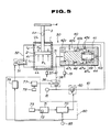
- the embodiment 4 is-shown in Fig. 5.
- the embodiment 4 has more simplified components and facilities than the embodiment 3.
- the first shut-off valve 40 and the second shut-off valve 51 are determined, the lower chamber pressure Pl, the upper chamber pressure Pu and the differential pressure between the pressures Pl and Pu of two chambers during the upward and the downward movement of the piston 2 as well as the relation between the upward and the downward movement of the slide and the necessary blank holding pressure can be made clear if the type of the press and the products to be fabricated are specified. Therefore, the differential pressure is controlled by the first shut-off valve 40, whereas the pressures in two chambers and the differential pressure are not directly detected and these are substituted by the axial angle of the crank.
- the pressure detectors 32 and 53 in the embodiment 3 are not included.
- the standard capability setter 74 is not provided, and the die cushion capability for all strokes of the piston 2 from the upper limit UL to the lower limit LL is memorized by the capability memorizing means 7.
- the control unit 70 controls the pressure regulating valve 60 by specifying the capability signal, inputted from the capability signal generating means 71, by the crank axial angle from the angle detector 85, and the cracking pressure of the first shut-off valve 40 is set. That is, the embodiment 3 forms a closed loop, while the embodiment 4 forms an open loop with one curve read from the capability memorizing means 72 as the preset value.
- control means to control the opening and the closing of the second shut-off valve 51 consists of the controller 75, which is a program sequencer. It control the opening and the closing of the second shut-off valve 51 in relation to the crank axial angle according to the predetermined procedure during the upward movement of the piston 2.
- the opening and the closing are controlled in the timing similar to the embodiment 3. The opening and closing procedure as well as the timing can be changed.
- this embodiment can provide more simplified structure and lower cost by omitting two pressure detectors (32 and 53) and by simplifying the control unit 70.
- each operation is determined not as the differential pressure between the pressures Pl and Pu in two chambers but is indirectly determined by the crank axial angle, the automatic adjustment of the die cushion capability can be freely, easily and simply performed during press fabrication if the capability diagram to be memorized by the capability memorizing means 72 is clearly defined.
- control unit 70 the capability signal generating means 71, the capability memorizing means 72, and the controllers 75 and 77 are furnished separately, whereas these means may be organically and integrally incorporated by the computer consisting of CPU, RAM, ROM, etc.
Landscapes
- Engineering & Computer Science (AREA)
- General Engineering & Computer Science (AREA)
- Mechanical Engineering (AREA)
- Physics & Mathematics (AREA)
- Acoustics & Sound (AREA)
- Aviation & Aerospace Engineering (AREA)
- Shaping Metal By Deep-Drawing, Or The Like (AREA)
- Presses And Accessory Devices Thereof (AREA)
Applications Claiming Priority (4)
| Application Number | Priority Date | Filing Date | Title |
|---|---|---|---|
| JP63262215A JPH0747237B2 (ja) | 1988-10-18 | 1988-10-18 | 空圧式ダイクッション装置 |
| JP262215/88 | 1988-10-18 | ||
| JP265620/88 | 1988-10-21 | ||
| JP63265620A JPH02112900A (ja) | 1988-10-21 | 1988-10-21 | 空圧式ダイクッション装置 |
Publications (2)
| Publication Number | Publication Date |
|---|---|
| EP0365317A1 true EP0365317A1 (fr) | 1990-04-25 |
| EP0365317B1 EP0365317B1 (fr) | 1994-03-09 |
Family
ID=26545450
Family Applications (1)
| Application Number | Title | Priority Date | Filing Date |
|---|---|---|---|
| EP89310734A Expired - Lifetime EP0365317B1 (fr) | 1988-10-18 | 1989-10-18 | Dispositif de matrice à coussin élastique pneumatique |
Country Status (4)
| Country | Link |
|---|---|
| US (1) | US5100113A (fr) |
| EP (1) | EP0365317B1 (fr) |
| KR (1) | KR900006116A (fr) |
| DE (1) | DE68913647T2 (fr) |
Cited By (8)
| Publication number | Priority date | Publication date | Assignee | Title |
|---|---|---|---|---|
| EP0531141A1 (fr) * | 1991-09-04 | 1993-03-10 | Toyota Jidosha Kabushiki Kaisha | Système de coussin hydraulique pour une presse, ayant une vanne d'arrêt pour déconnecter les boulons de pression d'alimentation hydraulique lors du contact de l'outil mobile avec la pièce |
| EP0673696A1 (fr) * | 1994-03-03 | 1995-09-27 | Toyota Jidosha Kabushiki Kaisha | Presse avec cylindres à gaz ou membres déformables plastiquement pour la distribution uniforme de la force de serre-flanc par les broches du coussin de presse |
| EP1074759A3 (fr) * | 1999-08-05 | 2003-04-23 | Diebolt International, Inc. | Ressort à gaz à course de retour temporisée |
| WO2011038947A1 (fr) * | 2009-09-29 | 2011-04-07 | Voith Patent Gmbh | Dispositif et procédé d'amortissement de choc de découpage pour machines de travail |
| CN103644235A (zh) * | 2013-12-31 | 2014-03-19 | 吉林大学 | 半主动并联空气弹簧 |
| CN103644234A (zh) * | 2013-12-17 | 2014-03-19 | 吉林大学 | 一种并联空气弹簧 |
| EP2957501A1 (fr) * | 2014-06-18 | 2015-12-23 | Goodrich Corporation | Système de régulation de longueur d'entretoise et de pression |
| ES2768449A1 (es) * | 2018-12-20 | 2020-06-22 | Bikkean Global Services S L U | Cilindro de gas |
Families Citing this family (15)
| Publication number | Priority date | Publication date | Assignee | Title |
|---|---|---|---|---|
| SE9302097L (sv) * | 1993-06-17 | 1994-07-11 | Stromsholmens Mek Verkstad | Degressiv gasfjäder |
| US5588641A (en) * | 1993-11-26 | 1996-12-31 | Stromsholmens Mekaniska Verkstad Ab | Gas spring which after compression has a time delayed return to its original length |
| US6131497A (en) * | 1999-04-07 | 2000-10-17 | Forward Industries, Llc | Gas cylinder with time delay |
| US6412616B1 (en) * | 2000-02-22 | 2002-07-02 | Lockheed Martin Corporation | Energy dissipation system |
| US6267360B1 (en) * | 2000-04-13 | 2001-07-31 | Metrol Co., Ltd. | Shock absorber |
| SE0001876D0 (sv) * | 2000-05-19 | 2000-05-19 | Stroemsholmen Ab | Anordning vid en press |
| JP2002224897A (ja) * | 2001-02-02 | 2002-08-13 | Komatsu Ltd | ダイクッション装置 |
| KR100435704B1 (ko) * | 2002-05-15 | 2004-06-12 | 현대자동차주식회사 | 트랜스퍼 프레스용 블록 리프트 장치 |
| US8296110B2 (en) * | 2006-10-04 | 2012-10-23 | Honda Motor Co., Ltd. | Forming condition determination method and forming condition determination system |
| JP5951591B2 (ja) * | 2013-12-26 | 2016-07-13 | アイダエンジニアリング株式会社 | ダイクッション力制御方法及びダイクッション装置 |
| RU177725U1 (ru) * | 2017-05-03 | 2018-03-06 | Федеральное государственное бюджетное образовательное учреждение высшего образования Иркутский государственный университет путей сообщения (ФГБОУ ВО ИрГУПС) | Самонастраивающийся виброизолятор |
| CN111322341B (zh) * | 2020-03-10 | 2021-05-11 | 季华实验室 | 空气弹簧、空气弹簧的控制系统和控制方法 |
| RU2755534C1 (ru) * | 2020-09-04 | 2021-09-17 | Федеральное государственное бюджетное образовательное учреждение высшего образования Иркутский государственный университет путей сообщения (ФГБОУ ВО ИрГУПС) | Устройство управления динамическим состоянием вибрационной технологической машины и способ для его реализации |
| RU2756393C1 (ru) * | 2020-10-09 | 2021-09-30 | Федеральное государственное бюджетное образовательное учреждение высшего образования Иркутский государственный университет путей сообщения (ФГБОУ ВО ИрГУПС) | Устройство формирования специфических режимов динамического состояния рабочего органа вибрационной технологической машины и способ для его реализации |
| CN112431884A (zh) * | 2020-10-09 | 2021-03-02 | 恒大恒驰新能源汽车研究院(上海)有限公司 | 空气弹簧附加气室、空气弹簧控制组件及车辆 |
Citations (4)
| Publication number | Priority date | Publication date | Assignee | Title |
|---|---|---|---|---|
| FR2386414A1 (fr) * | 1977-04-05 | 1978-11-03 | Smg Sueddeutsche Maschb | Presse comportant une course a vide avant la course de travail |
| DD147928A1 (de) * | 1980-01-23 | 1981-04-29 | Gerd Zemann | Vorrichtung zum ausgleich dynamischer massenkraefte an mechanischen pressen |
| GB2140871A (en) * | 1983-06-03 | 1984-12-05 | Bowthorpe Hellermann Ltd | Piston and cylinder actuator control |
| EP0284903A2 (fr) * | 1987-04-01 | 1988-10-05 | Gebr. Schmidt Fabrik Fur Feinmechanik | Presse à piston |
Family Cites Families (10)
| Publication number | Priority date | Publication date | Assignee | Title |
|---|---|---|---|---|
| DE147928C (fr) * | 1897-12-09 | |||
| US3593980A (en) * | 1969-04-21 | 1971-07-20 | Chicago Pneumatic Tool Co | Pneumatic balancer |
| US3807678A (en) * | 1972-09-19 | 1974-04-30 | Lord Corp | System for controlling the transmission of energy between spaced members |
| DE2456758C3 (de) * | 1973-12-05 | 1982-03-18 | Saab-Scania AB, Linköping | Hydraulische Presse |
| CS190125B1 (en) * | 1977-04-05 | 1979-05-31 | Jindrich Spacek | Hydraulic press periphery for hydromechanic drawing |
| JPS605930A (ja) * | 1983-06-22 | 1985-01-12 | 松下電器産業株式会社 | 脱臭装置 |
| JPS616968A (ja) * | 1984-06-21 | 1986-01-13 | Mitsubishi Electric Corp | インタ−ホン装置 |
| JPS6324770A (ja) * | 1986-07-16 | 1988-02-02 | Nec Home Electronics Ltd | アモルフアスシリコン薄膜トランジスタ液晶パネル駆動方法 |
| US4860571A (en) * | 1986-09-26 | 1989-08-29 | Kenneth L. Smedberg | Power press with improved cushioning system |
| US4774865A (en) * | 1987-09-22 | 1988-10-04 | Wallis Bernard J | Die stamping system |
-
1989
- 1989-10-06 US US07/420,160 patent/US5100113A/en not_active Expired - Fee Related
- 1989-10-18 KR KR1019890014981A patent/KR900006116A/ko not_active Ceased
- 1989-10-18 EP EP89310734A patent/EP0365317B1/fr not_active Expired - Lifetime
- 1989-10-18 DE DE68913647T patent/DE68913647T2/de not_active Expired - Fee Related
Patent Citations (4)
| Publication number | Priority date | Publication date | Assignee | Title |
|---|---|---|---|---|
| FR2386414A1 (fr) * | 1977-04-05 | 1978-11-03 | Smg Sueddeutsche Maschb | Presse comportant une course a vide avant la course de travail |
| DD147928A1 (de) * | 1980-01-23 | 1981-04-29 | Gerd Zemann | Vorrichtung zum ausgleich dynamischer massenkraefte an mechanischen pressen |
| GB2140871A (en) * | 1983-06-03 | 1984-12-05 | Bowthorpe Hellermann Ltd | Piston and cylinder actuator control |
| EP0284903A2 (fr) * | 1987-04-01 | 1988-10-05 | Gebr. Schmidt Fabrik Fur Feinmechanik | Presse à piston |
Cited By (12)
| Publication number | Priority date | Publication date | Assignee | Title |
|---|---|---|---|---|
| EP0531141A1 (fr) * | 1991-09-04 | 1993-03-10 | Toyota Jidosha Kabushiki Kaisha | Système de coussin hydraulique pour une presse, ayant une vanne d'arrêt pour déconnecter les boulons de pression d'alimentation hydraulique lors du contact de l'outil mobile avec la pièce |
| US5295383A (en) * | 1991-09-04 | 1994-03-22 | Toyota Jidosha Kabushiki Kaisha | Hydraulic cushioning system for press, having shut-off valve for disconnection of pressure-pin cylinders from power supply upon contact of movable die with workpiece |
| EP0673696A1 (fr) * | 1994-03-03 | 1995-09-27 | Toyota Jidosha Kabushiki Kaisha | Presse avec cylindres à gaz ou membres déformables plastiquement pour la distribution uniforme de la force de serre-flanc par les broches du coussin de presse |
| US5701778A (en) * | 1994-03-03 | 1997-12-30 | Toyota Jidosha Kabushiki Kaisha | Press having gas cylinders of plastically deformable members for even distribution of blank-holding force on pressure member through cushion pins |
| EP1074759A3 (fr) * | 1999-08-05 | 2003-04-23 | Diebolt International, Inc. | Ressort à gaz à course de retour temporisée |
| WO2011038947A1 (fr) * | 2009-09-29 | 2011-04-07 | Voith Patent Gmbh | Dispositif et procédé d'amortissement de choc de découpage pour machines de travail |
| US9050644B2 (en) | 2009-09-29 | 2015-06-09 | Voith Patent Gmbh | Device and method for the cutting shock damping of work machines |
| CN103644234A (zh) * | 2013-12-17 | 2014-03-19 | 吉林大学 | 一种并联空气弹簧 |
| CN103644235A (zh) * | 2013-12-31 | 2014-03-19 | 吉林大学 | 半主动并联空气弹簧 |
| EP2957501A1 (fr) * | 2014-06-18 | 2015-12-23 | Goodrich Corporation | Système de régulation de longueur d'entretoise et de pression |
| US9308991B2 (en) | 2014-06-18 | 2016-04-12 | Goodrich Corporation | Strut length and pressure regulation system |
| ES2768449A1 (es) * | 2018-12-20 | 2020-06-22 | Bikkean Global Services S L U | Cilindro de gas |
Also Published As
| Publication number | Publication date |
|---|---|
| EP0365317B1 (fr) | 1994-03-09 |
| DE68913647D1 (de) | 1994-04-14 |
| US5100113A (en) | 1992-03-31 |
| KR900006116A (ko) | 1990-05-07 |
| DE68913647T2 (de) | 1994-09-15 |
Similar Documents
| Publication | Publication Date | Title |
|---|---|---|
| EP0365317B1 (fr) | Dispositif de matrice à coussin élastique pneumatique | |
| EP0424122B1 (fr) | Equipement d'une étampe à coussin pour presse | |
| JPH0535791B2 (fr) | ||
| JPH0719202A (ja) | ソレノイド弁制御を備えた電空変換器 | |
| CN116464812A (zh) | 一种高压智能分级调压阀及控制方法 | |
| EP0439621A4 (en) | Pressure oil feed circuit device for hydraulic cylinder of operation machine | |
| HU206912B (en) | Valve system operated by electromagnet | |
| US4226482A (en) | Brake accelerator for a fluid pressure brake system | |
| KR20120013933A (ko) | 유압 변속기 제어 장치 | |
| US5586435A (en) | Hydraulic closed loop control system | |
| US4299427A (en) | Adjusting arrangement for variable load valve device | |
| US4729300A (en) | Press cushion for a mechanical press | |
| SE510463C2 (sv) | Förfarande och anordning för att eliminera kolvstångsrusning vid start av pneumatisk motor | |
| US4599887A (en) | Apparatus for controlling dynamic characteristics of press load | |
| JPH02112900A (ja) | 空圧式ダイクッション装置 | |
| US3941508A (en) | Automatic pressure control system | |
| JPS6411836B2 (fr) | ||
| JPH0446201A (ja) | 空圧シリンダ用切換弁 | |
| GB2160284A (en) | Servo power boosting apparatus | |
| SE463326B (sv) | Foerfarande och anordning foer noggrann positionering av lastbaerande tryckfluidcylindrar | |
| US5261314A (en) | Directional control valve for pneumatic cylinder | |
| JPH08219102A (ja) | アンビルを用いる超高圧作出装置における圧力制御方法 | |
| JPS6249418A (ja) | 空気圧力調整装置 | |
| JPH08303404A (ja) | シリンダ駆動装置 | |
| DE311180C (fr) |
Legal Events
| Date | Code | Title | Description |
|---|---|---|---|
| PUAI | Public reference made under article 153(3) epc to a published international application that has entered the european phase |
Free format text: ORIGINAL CODE: 0009012 |
|
| AK | Designated contracting states |
Kind code of ref document: A1 Designated state(s): CH DE FR GB IT LI |
|
| 17P | Request for examination filed |
Effective date: 19900615 |
|
| 17Q | First examination report despatched |
Effective date: 19911127 |
|
| GRAA | (expected) grant |
Free format text: ORIGINAL CODE: 0009210 |
|
| RAP1 | Party data changed (applicant data changed or rights of an application transferred) |
Owner name: AIDA ENGINEERING LTD. |
|
| AK | Designated contracting states |
Kind code of ref document: B1 Designated state(s): CH DE FR GB IT LI |
|
| PG25 | Lapsed in a contracting state [announced via postgrant information from national office to epo] |
Ref country code: IT Free format text: LAPSE BECAUSE OF FAILURE TO SUBMIT A TRANSLATION OF THE DESCRIPTION OR TO PAY THE FEE WITHIN THE PRE;WARNING: LAPSES OF ITALIAN PATENTS WITH EFFECTIVE DATE BEFORE 2007 MAY HAVE OCCURRED AT ANY TIME BEFORE 2007. THE CORRECT EFFECTIVE DATE MAY BE DIFFERENT FROM THE ONE RECORDED.SCRIBED TIME-LIMIT Effective date: 19940309 Ref country code: LI Effective date: 19940309 Ref country code: CH Effective date: 19940309 Ref country code: FR Free format text: THE PATENT HAS BEEN ANNULLED BY A DECISION OF A NATIONAL AUTHORITY Effective date: 19940309 |
|
| REF | Corresponds to: |
Ref document number: 68913647 Country of ref document: DE Date of ref document: 19940414 |
|
| REG | Reference to a national code |
Ref country code: CH Ref legal event code: PL |
|
| EN | Fr: translation not filed | ||
| PG25 | Lapsed in a contracting state [announced via postgrant information from national office to epo] |
Ref country code: GB Effective date: 19941018 |
|
| PLBE | No opposition filed within time limit |
Free format text: ORIGINAL CODE: 0009261 |
|
| STAA | Information on the status of an ep patent application or granted ep patent |
Free format text: STATUS: NO OPPOSITION FILED WITHIN TIME LIMIT |
|
| 26N | No opposition filed | ||
| GBPC | Gb: european patent ceased through non-payment of renewal fee |
Effective date: 19941018 |
|
| PG25 | Lapsed in a contracting state [announced via postgrant information from national office to epo] |
Ref country code: DE Effective date: 19950701 |