EP0365375A1 - Rohrförmiges Element zur Bildung eines Riegelloches - Google Patents
Rohrförmiges Element zur Bildung eines Riegelloches Download PDFInfo
- Publication number
- EP0365375A1 EP0365375A1 EP89402530A EP89402530A EP0365375A1 EP 0365375 A1 EP0365375 A1 EP 0365375A1 EP 89402530 A EP89402530 A EP 89402530A EP 89402530 A EP89402530 A EP 89402530A EP 0365375 A1 EP0365375 A1 EP 0365375A1
- Authority
- EP
- European Patent Office
- Prior art keywords
- tube
- cutout
- door
- modular
- unitary
- Prior art date
- Legal status (The legal status is an assumption and is not a legal conclusion. Google has not performed a legal analysis and makes no representation as to the accuracy of the status listed.)
- Withdrawn
Links
- 238000000034 method Methods 0.000 claims abstract description 23
- 238000007789 sealing Methods 0.000 claims description 6
- 238000009434 installation Methods 0.000 claims description 4
- 238000005304 joining Methods 0.000 claims description 3
- 230000035515 penetration Effects 0.000 claims description 3
- 238000005520 cutting process Methods 0.000 claims description 2
- 239000007787 solid Substances 0.000 abstract description 5
- 230000000149 penetrating effect Effects 0.000 abstract 1
- 239000002184 metal Substances 0.000 description 6
- 229910052751 metal Inorganic materials 0.000 description 6
- 229910000746 Structural steel Inorganic materials 0.000 description 4
- 239000000203 mixture Substances 0.000 description 3
- 244000245420 ail Species 0.000 description 2
- 238000004873 anchoring Methods 0.000 description 2
- 230000000694 effects Effects 0.000 description 2
- 238000004519 manufacturing process Methods 0.000 description 2
- 230000007246 mechanism Effects 0.000 description 2
- 239000000047 product Substances 0.000 description 2
- 230000000750 progressive effect Effects 0.000 description 2
- 230000002787 reinforcement Effects 0.000 description 2
- 230000002441 reversible effect Effects 0.000 description 2
- 238000005303 weighing Methods 0.000 description 2
- 238000005452 bending Methods 0.000 description 1
- 230000002146 bilateral effect Effects 0.000 description 1
- 239000007795 chemical reaction product Substances 0.000 description 1
- 230000006835 compression Effects 0.000 description 1
- 238000007906 compression Methods 0.000 description 1
- 238000009826 distribution Methods 0.000 description 1
- 239000000428 dust Substances 0.000 description 1
- 229940082150 encore Drugs 0.000 description 1
- 238000005259 measurement Methods 0.000 description 1
- 230000004048 modification Effects 0.000 description 1
- 238000012986 modification Methods 0.000 description 1
- 238000010422 painting Methods 0.000 description 1
- 230000008439 repair process Effects 0.000 description 1
- 230000000284 resting effect Effects 0.000 description 1
- 238000010079 rubber tapping Methods 0.000 description 1
- 238000010008 shearing Methods 0.000 description 1
- 238000003466 welding Methods 0.000 description 1
- 239000002023 wood Substances 0.000 description 1
Images





Classifications
-
- E—FIXED CONSTRUCTIONS
- E05—LOCKS; KEYS; WINDOW OR DOOR FITTINGS; SAFES
- E05C—BOLTS OR FASTENING DEVICES FOR WINGS, SPECIALLY FOR DOORS OR WINDOWS
- E05C9/00—Arrangements of simultaneously actuated bolts or other securing devices at well-separated positions on the same wing
- E05C9/02—Arrangements of simultaneously actuated bolts or other securing devices at well-separated positions on the same wing with one sliding bar for fastening when moved in one direction and unfastening when moved in opposite direction; with two sliding bars moved in the same direction when fastening or unfastening
- E05C9/028—Arrangements of simultaneously actuated bolts or other securing devices at well-separated positions on the same wing with one sliding bar for fastening when moved in one direction and unfastening when moved in opposite direction; with two sliding bars moved in the same direction when fastening or unfastening externally mounted on the wing, i.e. surface mounted
-
- E—FIXED CONSTRUCTIONS
- E05—LOCKS; KEYS; WINDOW OR DOOR FITTINGS; SAFES
- E05C—BOLTS OR FASTENING DEVICES FOR WINGS, SPECIALLY FOR DOORS OR WINDOWS
- E05C9/00—Arrangements of simultaneously actuated bolts or other securing devices at well-separated positions on the same wing
- E05C9/18—Details of fastening means or of fixed retaining means for the ends of bars
- E05C9/1808—Keepers
-
- E—FIXED CONSTRUCTIONS
- E05—LOCKS; KEYS; WINDOW OR DOOR FITTINGS; SAFES
- E05B—LOCKS; ACCESSORIES THEREFOR; HANDCUFFS
- E05B63/00—Locks or fastenings with special structural characteristics
- E05B63/0056—Locks with adjustable or exchangeable lock parts
-
- E—FIXED CONSTRUCTIONS
- E05—LOCKS; KEYS; WINDOW OR DOOR FITTINGS; SAFES
- E05B—LOCKS; ACCESSORIES THEREFOR; HANDCUFFS
- E05B63/00—Locks or fastenings with special structural characteristics
- E05B63/14—Arrangement of several locks or locks with several bolts, e.g. arranged one behind the other
- E05B63/143—Arrangement of several locks, e.g. in parallel or series, on one or more wings
Definitions
- the subject of the present invention is a method of equipping a door frame, or a door, using a locksmith element having at least one cutout, possibly through, forming a vertical keeper, which consists in use, as a locksmith element, an element of rectangular parallelepiped section and in one of the faces of which is or are provided (s) the cutout (s).
- the vertical strikes consist of a parallelepipedic "box", one side face of which has one or two cutouts adapted to receive a corresponding number of bolts depending on a bolt or lock chest mounted opposite. screw, and this housing is dimensioned so that its horizontal faces can be aligned with that of said trunk.
- a conventional keeper therefore has dimensions which are simply the dimensions necessary and sufficient for the reception function of the bolts.
- the strikes and latches are commonly fixed by simple means, namely by wood screws on the frames or wooden doors and by self-tapping screws, for example Parker screws, on the frames or metal doors.
- angle iron in which the face of the housing coming to be applied to the frame forms part of the wing of an angle iron longer than said face and whose angle comes follow the rebate of the doorframe. This angle iron thus offers fixing points more distant from each other than would the case alone and therefore it reinforces the fixing.
- the object of the present invention is to remedy this drawback by proposing a reliable and economical method, the implementation of which results in the creation of equipment with a resistance far greater than that of existing equipment.
- the method according to the invention consists in using, as an element of rectangular parallelepiped section, a one-piece element, produced in the form of a tube, having a length greater than 25 cm, that is to say a length much greater than what is necessary and sufficient to accommodate one or even two bolts.
- the resulting product is significantly more resistant than a striker angle because, as known to those skilled in the art, for the same thickness of metal, a tube resists bending and shearing much better than an angle, because opposing forces.
- FR-A-2 251 215 the use of housings made up of two J-shaped profiles which partially fit into each other to form, after assembly by screwing, an element of rectangular parallelepiped section extended on one of its faces by a wing forming a "headrest" coming to be placed, as the case may be, against the rebate of the jamb, side opposite to the hinges, or against the facing edge -vis the door.
- the method consists in using a tube whose ends are open and whose length is greater than the height of a standard door, and in cutting said tube, called “unitary element" ", to the desired length.
- the cut end can be plugged with a plastic end cap and the cutouts, intended to receive the bolt (s) of one or more latches, are made at the desired locations along the length of the tube.
- a tube is used whose ends are open and whose length is less than the height of a standard door and said tube is joined to at least one tube of the same type by juxtaposition edge to edge of their open ends, with prior placement of a male connector therebetween, to form an assembly called "modular element".
- Such modular elements which can also be cut to the desired length, are easier to maneuver and install than a unitary element, as defined above, and they can be recovered and possibly reused in another configuration in the event of move.
- a piece of equipment can comprise modules having cutouts and modules not having any, depending on the number and relative arrangement of the latches.
- the method according to the invention also consists in fixing the unitary or modular element to the floor and / or to the ceiling by threading into its lower end and / or its upper end, a solid fixing block and having a axial thread adapted to receive one end of a screw, the other of which end is anchored respectively in the ground and / or the ceiling.
- the assembly can be further reinforced by threading a fixing block into the upper end of said element. solid and having an axial thread adapted to receive one end of a screw whose other end cooperates with a sealing lug sealed in the adjacent wall.
- side walls when the frame to be fitted is placed on a wall perpendicular to two other walls not far from each other, called “side walls”, one can join the upper end of the unitary or modular element, to a tube or two half-tubes of the same section, called “side tubes”, bearing against, or anchored in, the neighboring side wall.
- opposite wall we can join the upper end of the unitary or modular element, at one of the ends of a tube of the same section, called “transverse tube”, the opposite end of said transverse tube bearing against, or being anchored in, the opposite wall.
- the method according to the invention makes it possible not only to create integral vertical strikes, but also a horizontal strike.
- the method also consists in providing the horizontal part of the jamb of a unitary or modular horizontal element in one of the faces of which a cutout forming a horizontal keeper is provided, and of joining said horizontal element to the unitary or modular element equipping the vertical part of the jamb.
- said element contains, at each cutout forming strike, internal means for adjusting the space offered at the bolt bolt mounted vis-à-vis, for its penetration into said tubular element.
- Such adjustment means are known from FR-A-2 599 775 in the name of the Applicant, but their mounting in a tube requires a particular technique which will be described later.
- the invention also relates to the locksmith element used for implementing the method according to the invention.
- Figure 2 differs from the previous only by the fact that the equipment shown uses, instead of locks 1b, locks 1c whose operation actuates not only a horizontal bolt to make it penetrate the keeper 2b, but also a vertical rod 3, the free end of which is received, in the upper part, in a horizontal keeper 4 and, in the lower part, in a ground keeper 5 sealed therein.
- the strikes 2a, 2b and 4 are independent of each other and their dimensions are a function of the bolts to be received.
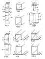
- the invention proposes to make the cutouts forming keepers in a tube of rectangular parallelepiped section, which tube can be in one piece or, as shown in Figure 14, formed of 'basic elements.
- the unitary element or the modular elements will be designated either by these terms or by the expression "the tubular element” or more simply “the tube” or, where appropriate, "the module”.
- the tube can have a square ( Figures 5, 7 and 9) or rectangular ( Figures 6, 8 and 10) section, and its face intended to be applied to the frame or door - depending on the intended use - can be extended by two coplanar wings 6 ( Figures 7 and 9) or one ( Figures 9 and 10).
- the junction between the modules, such as the module 7 shown in Figure 4, and in more detail in Figure 15, is done using fittings, such as the fitting 8 in Figure 3.
- the fitting 8 has two male parts 9a and 9b, the section of which is slightly less than the section of the cavity 10 of the module 7.
- the connector 8 comprises a middle part 11 whose section is equal to the external section of the module 7 so that two shoulders 12a and 12b are formed at the junction between the male parts 9a and 9b and the middle part 11. It is thus understood that the part 9b of the connector 8 can be introduced into the cavity 10 of the module 7 until the shoulder 12b comes in abutment against the free edge of the module 7.
- the male part 9a of the connector 8 can likewise be threaded into the cavity of a another module 7.
- the male parts 9a and 9b have holes 13 adapted to come into correspondence with holes 14 provided in the modules 7, for the passage of assembly screws.
- braces M delimit the modules 7 and the braces R the connections 8.
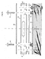
- the module 7 has a cutout 15 adapted to receive the bolt of a lock.
- the modular composition of FIG. 14 thus offers three cutouts 15. It is understood that the same module could have several cutouts 15 or none, depending on the length of the module and the distribution of the latches.
- the reference 16 designates adjustment means whose structure and utility will emerge from the description of FIGS. 21 and 22.
- a fixing block 17 is used, as shown in FIG. 11. It is a solid metal block whose cross section is slightly smaller than that of the cavity 10 of the module 7 and one of which of the ends forms stop plate 18.
- the stop plate 18 has the same section as the module 7 so that, if the block 17 is threaded into the cavity 10 of a module 7, the edges of the plate stop flush with those of said module 7.
- FIG 16 shows the upper and lower ends of tubular equipment according to the invention.
- a fixing block 17 is threaded into the lower and upper ends of the end modules 7.
- a long screw 22 is screwed and the part of the screw 22 which protrudes from the stop plate 18 penetrates deeply into the ground S.
- a long screw 23 secured to a nut 24a and the end of which penetrates into the ceiling P. The operation of the nut 24a more or less takes out the screw in the manner of a jack and a counter nut 24b makes it possible to immobilize the assembly.
- Figure 17 shows means that can be used when anchoring in the ground is not possible directly above the modular equipment.
- a plate 25 is used in which two tapped holes 26 and 27 with reverse taper are provided.
- a screw 28a ensures the connection between the plate 25 and the block 17 threaded into the module 7, and a screw 28b ensures the anchoring to the ground of the plate 25.
- Figure 18 shows the upper part of the equipment of a door opening in a wall 29 close to a wall 30 vis-à-vis.
- a modular composition which will go beyond the upper part of the frame, thread a block 17 into the free end of the upper module 7 and join to said block 17, by means of a screw 31, one of the ends of a tubular element 32, the other end of which is sealed in the wall 30.
- a square connector could be used, as shown in FIG. 13, one of the branches of the bracket coming to be housed in the module 7 in place of the block 17, while its other branch comes into a suitable tubular element replacing the element 32.
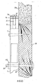
- FIG. 20 shows the use of another possible means of reinforcement: a sealing tab 36, the forked end of which is sealed in the concrete of the wall 29c, at its opposite end joined to the fixing block 17 by a screw 37 It is also possible to consolidate the connection between the jamb 38 and the masonry by sealing in the latter a sealing tab 36 ′ whose protruding part out of the concrete is received in a recess of the jamb and interposed between the module 7 and the jamb. A through screw 39 immobilizes the whole while cooperating with a nut 40.
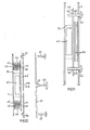
- FIGS. 21 and 22 show two possible embodiments for such adjustment means which are shown diagrammatically at 16 in FIG. 15.
- shim s
- one of the faces of the module or tube 7 has a cutout 15 for the passage of the bolt 42 of the lock.
- a movable plate 45 is introduced into the tube 7 through the cutout 15 and it has holes 54.
- Holes 44 having the same spacing as the holes 54 are formed in the tube 7 and screws 55 connect the plate 45 to the tube 7.
- Shims of thickness 56 in a desired number are interposed between the internal wall of the tube 7 and the plate 45.
- a progressive adjustment by springs is used.
- one of the faces of the module or tube 7 has a cutout 15 for the passage of the bolt 42 of the lock. Holes 43,43-44,44 having the same spacing pass through the tube 7 right through.
- a movable plate 45 'pierced and milled at the same distance as the holes 43,43-44,44 is introduced into the tube 7 by the cutout, after which compression springs 46 are also introduced therein.
- the holes 43 are crimped by expanding nuts 47 with tapped barrel.
- By the holes 44 it suffices to screw screws 48 to obtain a progressive and precise adjustment.
- the screws 48 engage the threads of the barrels of the crimped nuts 47.
- a nut 52 is also crimped in the cover plate 49 and it is suitable to receive a "violin” screw or a “knurled” button 53, the projecting part of which passes through aligned holes 41a and 41b respectively provided in the tube 7 and in the plate 45 ′ and is likely to push against the bolt 42 to wedge it, if desired.
- the plate 45 'hides the adjustment means and further strengthens the assembly by forming a third wall.
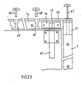
- FIG. 23 shows the embodiment according to the invention of a horizontal keeper adapted to receive the end of a rod 65.
- This keeper is produced by a cutout 15 made in a horizontal tubular equipment 7a provided, as previously, with means of adjustment 16.
- the tube 7a and the tube 7 are joined by means of a plate 66, one end of which covers the upper end of the tube 7, previously provided with a block 17, the assembly being secured by means of a screws 67 passing through the plate 66 and engaging with the block 17.
- the plate is joined to the tube 7a by means of screws 68 engaging with crimped nuts 69. Four of these crimped nuts 69 are provided to allow possible reversal of the tube 7a and, for the same reason, the cutout 15 is through.
- anti-pinch angle bars obstruct the taking of a lever, but have no effect against the use of a jack supported on the opposite wall or on the door frame.
- the tubular equipment forming keepers according to the invention resists but it could happen that it is the fixing of locks which gives way: in fact, if the keeper resists, the active bolt will behave as a lever, the part of the chest of the lock near the edge of the door will serve as a fulcrum for this lever, and the part of the trunk away from the edge of the door, as well as the dead bolt, will lift. It will follow that the trunk fixing screws will tear off.
- each lock 57a, 57b comprises a trunk 58 and a bolt having a leading end called “active bolt” 59 and a trailing end, called “dead bolt” 60.
- the door 61 is provided with a tubular equipment 7b which is distinguished from the equipment 7 described above only by the fact that the cutouts 15 are through. The same references therefore designate the same parts as before.
- the dead bolt 60 projects out of the tube 7b, on the side opposite the edge of the door.
- the dead bolt 60 When the bolt is closed (57b), the dead bolt 60 is located under the tube 7a and if a violent stress is transmitted to the active bolt 59 which, by bearing on the edge of the trunk 58 closest to the edge of the door, acts as a lever, the lifting of the dead bolt 60 is prevented by the tube 7b.
- the trunk fixing screws 62 are therefore protected against any tearing force.
- Tubular equipment 7c can be fixed to the door 61 on the hinge side with interposition between, on the one hand, the equipment 7b and 7c and, on the other hand, the door 61, of a shielding sheet 63.
- a tubular piece of equipment 7d is placed immobilized on the ground using a block 17 as above and the upper part of which can be fixed by any of the means described above.
- the tube 7d is secured to the tube 7c by welded hinges 64.
- a shielding sheet, not shown, can be interposed between the tube 7d and the masonry to reinforce it.
- an independent base 70 consisting of a flat or section full of a length at least equal to that of the element 76.
- the length of the base 70 can be such that it is common to several elements 76. Instead of a dish, it could be a U-shaped profile, of a tube, etc.
- On this base 70 are fixed threaded inserts 71, the barrel of which is adapted to pass through bores 90 provided in the element 76 and to receive screws 72 whose rod passes through bores 91 made in vis-à-vis in the same element 76.
- the base 70 can be fixed to the frame 93 by screws 94 and 95, through bolts 73 cooperating with nuts 79, inserts, or by welding, riveting or any other appropriate means.
- Additional holes 78 made in the element 76 make it possible to absorb and conceal the screw heads 94 and 95 and the nuts 79 of the through bolts 73.
- the base 70 provides: - improved fixing due to the fact that the screws 94, 95 or 73 pass entirely through it and are completely housed in the wooden support 93 (there is therefore no longer any length of screw lost in the trunk of the strikes), a greater adjustment amplitude as a function of the thickness of the base 70, an improved aesthetic, the screws 73, 94, 95 and fixing nuts 79 being hidden by the element 76, - the possibility of installing a screw 95 in the most stressed place in the event of weighing, namely in the center of the base, - greater ease of installation and removal, without affecting the solidity of the initial fixing (in the event of painting repairs, for example), and - a possibility of easy modification of the setting.
- the adjustment possibilities can be further increased by inserting washers or, better, one or more plates 77 having holes aligned with those of the element 76, these plates 77 being able to be placed: - between the base 70 and the frame 93, - between the base 70 and the tubular element 76, as shown in FIG. 25, and / or - inside said element 76.
- the cuts reduce the resistance of the tubular element to weighing. This can be compensated for by using a force plate 80 which can also serve as a hub cap and which is immobilized on the element 76 by means of the screws 72 cooperating with the inserts 71.
- This force plate can be produced in the form of '' a dish, an angle iron, a U-profile, etc.
- FIG. 25 is particularly advantageous in the case of doors with two leaves, of small thickness, of thin frames, etc.
- a similar embodiment can be designed to be placed on the door, instead of be on the doorframe, in order to clamp the dead bolt, preventing, in the event of a strong push, the bolt from detuning.
- FIG. 26 An interesting variant is illustrated in FIG. 26: a base 70 ′ folded, at each end, in the shape of a U and pierced at 82 in the wings of said U, is adapted to receive the tubular element 76 ′, the two open ends of which are closed by a threaded block 17, similar to that bearing the same reference in FIG. 11. Screws 83 provide a solid connection between the base 70 ′ and the element 76 ′. A force plate / hubcap 84 is fixed by any suitable means, not shown, to the element 76 ′.
- the element 76 ′ has a cutout on each of its four faces, only three of which, 75a, 75b, 75c, are visible in the figure. As can be seen, these cutouts are offset from one another along the longitudinal axis of the element 76 ′.
- the element 76 ′ can be mounted in the cradle that constitutes the base 70 ′ by exposing, towards the outside, the cutout that is desired, which gives four possibilities, and moreover by inverting the left ends and right of the element 76 ′, which multiplies by two these possibilities of choice of positioning of the cutout, and facilitates the adjustment.
- This embodiment also makes it possible to mount the device indifferently on doors opening by pulling, pushing, to the left or to the right.
- the invention provides a method and means which are adaptable on a wooden frame, on metal frames or on a fixed door leaf with two doors. Their application can be extended to the protection of locks and locks and to that of hinges, as well as to the installation of a shielding sheet.
- the invention optionally makes it possible to form a metal frame having its own independent fasteners, which frame reinforces the frame.
- the invention can also be used in the case of mortise or mortise locks: the holding of the strike notched in the rebate of the jamb is reinforced by the passage of tubular equipment in front of such a lock.
- a thin or hollow door can be replaced by a thicker door, by simply compensating for the difference in thickness with a wooden slat interposed between the tubular equipment according to the invention and the original jamb.
- the method according to the invention can be applied without difficulty in the case of so-called "overlapping" doors.
- These doors are thicker than the depth of the rebate and the cover is fitted with a seal for air tightness.
- Such doors require the installation of special, ineffective, non-adjustable strikes (the thicknesses of the covers and the seal are different depending on the manufacturer).
- a thicker tube for example rectangular, will be used to compensate for the thickness of the covering.
- the method according to the invention is designed to adapt: - at all door heights, - all the products on the market, thanks to its adjustment possibilities, - mounting either to the left or to the right of the pivot, - disassembly for reuse elsewhere, because the equipment is reversible, can be cut, extended, - different fixing possibilities, traditional, original and combinable, - any development to meet standardization requirements, - to an easy, fast implementation, requiring neither special tools or know-how, and - an adjustment, possibly carried out by the user himself.
Landscapes
- Engineering & Computer Science (AREA)
- Mechanical Engineering (AREA)
- Tents Or Canopies (AREA)
- Door And Window Frames Mounted To Openings (AREA)
Applications Claiming Priority (2)
| Application Number | Priority Date | Filing Date | Title |
|---|---|---|---|
| FR8812086A FR2636661B1 (fr) | 1988-09-16 | 1988-09-16 | Procede d'equipement d'un chambranle de porte a l'aide d'un element de serrurerie, et elements de serrurerie, notamment modulaires, pour la mise en oeuvre de ce procede |
| FR8812086 | 1988-09-16 |
Publications (1)
| Publication Number | Publication Date |
|---|---|
| EP0365375A1 true EP0365375A1 (de) | 1990-04-25 |
Family
ID=9370058
Family Applications (1)
| Application Number | Title | Priority Date | Filing Date |
|---|---|---|---|
| EP89402530A Withdrawn EP0365375A1 (de) | 1988-09-16 | 1989-09-15 | Rohrförmiges Element zur Bildung eines Riegelloches |
Country Status (3)
| Country | Link |
|---|---|
| EP (1) | EP0365375A1 (de) |
| FR (1) | FR2636661B1 (de) |
| PT (1) | PT91733A (de) |
Citations (2)
| Publication number | Priority date | Publication date | Assignee | Title |
|---|---|---|---|---|
| FR2251215A6 (de) * | 1973-11-13 | 1975-06-06 | Fichet Bauche | |
| FR2363681A1 (fr) * | 1976-08-31 | 1978-03-31 | Pierre Ind | Gache de serrure |
-
1988
- 1988-09-16 FR FR8812086A patent/FR2636661B1/fr not_active Expired - Fee Related
-
1989
- 1989-09-15 PT PT9173389A patent/PT91733A/pt not_active Application Discontinuation
- 1989-09-15 EP EP89402530A patent/EP0365375A1/de not_active Withdrawn
Patent Citations (2)
| Publication number | Priority date | Publication date | Assignee | Title |
|---|---|---|---|---|
| FR2251215A6 (de) * | 1973-11-13 | 1975-06-06 | Fichet Bauche | |
| FR2363681A1 (fr) * | 1976-08-31 | 1978-03-31 | Pierre Ind | Gache de serrure |
Also Published As
| Publication number | Publication date |
|---|---|
| FR2636661A1 (fr) | 1990-03-23 |
| FR2636661B1 (fr) | 1994-02-11 |
| PT91733A (pt) | 1990-03-30 |
Similar Documents
| Publication | Publication Date | Title |
|---|---|---|
| CA2058615C (fr) | Dispositif de renfort de cadre et de porte | |
| EP2580417B1 (de) | Türelement | |
| EP0801191B1 (de) | Schliessblech und Basis sowie Basiseinsatz für ein solches Schliessblech | |
| EP0409754B1 (de) | Verriegelungsvorrichtung für ein Schiebefenster, eine Schiebetür o.dgl. | |
| FR2920807A1 (fr) | Dispositif de fermeture a plusieurs points renforcant la securite des ouvrants dans l'habitat | |
| EP0365375A1 (de) | Rohrförmiges Element zur Bildung eines Riegelloches | |
| FR2772810A3 (fr) | Poteau technique perfectionne pour porte anti-vandalisme | |
| FR2497866A1 (fr) | Porte de securite | |
| FR2604476A2 (fr) | Bloc-porte adaptable anti-effraction | |
| EP3401490B1 (de) | Türschutzstruktur und armor block mit einer solchen struktur | |
| EP0252781A2 (de) | Einstellbares Schliessblech und einbruchsichere Montagevorrichtung | |
| FR2934871A1 (fr) | Dispositif antieffraction d'une porte pour armoire et armoire equipee d'un tel dispositif | |
| FR2867220A1 (fr) | Vantail et porte basculante comprenant un tel vantail | |
| FR2677067A1 (fr) | Systeme de gache reglable pour pene de serrure ou de verrou. | |
| FR2954391A1 (fr) | Ensemble chambranle contre-chambranle | |
| EP0125998A2 (de) | Panzertür aus Metall | |
| EP1002927B1 (de) | Einbruchhemmende Türeinheit mit getafeltem Türblatt und eine Kombination der Armierungen des Blattes und des Türstocks | |
| FR2553465A1 (fr) | Ensemble de fermeture anti-effraction pour emplacement de porte ou fenetre | |
| FR2867219A1 (fr) | Vantail et porte anti-effraction | |
| FR2669072A1 (fr) | Gache pour le verrouillage de portes, volets, etc. a deux vantaux. | |
| FR2463253A1 (fr) | Porte blindee | |
| FR2954392A1 (fr) | Ensemble chambranle contre-chambranle | |
| FR2772809A3 (fr) | Poteau technique perfectionne pour porte anti-vandalisme | |
| EP0275807A1 (de) | Treibstangenverschluss für Türen oder Fenster | |
| FR2581414A1 (fr) | Porte anti-effraction |
Legal Events
| Date | Code | Title | Description |
|---|---|---|---|
| PUAI | Public reference made under article 153(3) epc to a published international application that has entered the european phase |
Free format text: ORIGINAL CODE: 0009012 |
|
| AK | Designated contracting states |
Kind code of ref document: A1 Designated state(s): BE CH DE ES FR GB IT LI LU NL |
|
| 17P | Request for examination filed |
Effective date: 19901022 |
|
| 17Q | First examination report despatched |
Effective date: 19920918 |
|
| STAA | Information on the status of an ep patent application or granted ep patent |
Free format text: STATUS: THE APPLICATION IS DEEMED TO BE WITHDRAWN |
|
| 18D | Application deemed to be withdrawn |
Effective date: 19930330 |