EP0365418A1 - Förderer zum Führen von gedruckten Leiterplatten längs einer Strecke mit wechselnder Neigung - Google Patents
Förderer zum Führen von gedruckten Leiterplatten längs einer Strecke mit wechselnder Neigung Download PDFInfo
- Publication number
- EP0365418A1 EP0365418A1 EP89402859A EP89402859A EP0365418A1 EP 0365418 A1 EP0365418 A1 EP 0365418A1 EP 89402859 A EP89402859 A EP 89402859A EP 89402859 A EP89402859 A EP 89402859A EP 0365418 A1 EP0365418 A1 EP 0365418A1
- Authority
- EP
- European Patent Office
- Prior art keywords
- cards
- guides
- path
- conveyor according
- guide
- Prior art date
- Legal status (The legal status is an assumption and is not a legal conclusion. Google has not performed a legal analysis and makes no representation as to the accuracy of the status listed.)
- Withdrawn
Links
Images

Classifications
-
- B—PERFORMING OPERATIONS; TRANSPORTING
- B23—MACHINE TOOLS; METAL-WORKING NOT OTHERWISE PROVIDED FOR
- B23K—SOLDERING OR UNSOLDERING; WELDING; CLADDING OR PLATING BY SOLDERING OR WELDING; CUTTING BY APPLYING HEAT LOCALLY, e.g. FLAME CUTTING; WORKING BY LASER BEAM
- B23K3/00—Tools, devices or special appurtenances for soldering, e.g. brazing, or unsoldering, not specially adapted for particular methods
- B23K3/06—Solder feeding devices; Solder melting pans
- B23K3/0646—Solder baths
- B23K3/0669—Solder baths with dipping means
- B23K3/0676—Conveyors therefor
-
- H—ELECTRICITY
- H05—ELECTRIC TECHNIQUES NOT OTHERWISE PROVIDED FOR
- H05K—PRINTED CIRCUITS; CASINGS OR CONSTRUCTIONAL DETAILS OF ELECTRIC APPARATUS; MANUFACTURE OF ASSEMBLAGES OF ELECTRICAL COMPONENTS
- H05K13/00—Apparatus or processes specially adapted for manufacturing or adjusting assemblages of electric components
- H05K13/0061—Tools for holding the circuit boards during processing; handling transport of printed circuit boards
-
- H—ELECTRICITY
- H05—ELECTRIC TECHNIQUES NOT OTHERWISE PROVIDED FOR
- H05K—PRINTED CIRCUITS; CASINGS OR CONSTRUCTIONAL DETAILS OF ELECTRIC APPARATUS; MANUFACTURE OF ASSEMBLAGES OF ELECTRICAL COMPONENTS
- H05K3/00—Apparatus or processes for manufacturing printed circuits
- H05K3/22—Secondary treatment of printed circuits
- H05K3/26—Cleaning or polishing of the conductive pattern
Definitions
- the present invention relates to a conveyor for driving printed circuit boards along a path with variable slopes.
- It relates, in particular, to a conveyor specifically designed for a machine for cleaning printed circuit boards, such as is usually found at the end of the production line for printed circuit boards.
- the card path follows successive sections of different slopes, a first descending section passing through a prewash station by spraying with solvent, a second horizontal section passing through a washing tub filled with solvent, then a third ascending section passing through a final rinsing station by solvent spraying, the two descending and ascending sections also being respectively preceded and followed by a short horizontal section for connection to adjacent machines.
- conveyors are usually wire mesh conveyors on which the cards are simply laid, but these present a number of problems: - the miniaturization of the components becomes such that the cards are lighter and lighter and the solvent jets which they receive from below in the spraying stations tend to move them, or even to turn them over completely, and we must reduce the power of the lower jets in favor of the upper jets, - the overall density of the card, substrate plus components, becomes lower than that of the solvent, so that the cards tend to float in the washing tank; they are therefore no longer properly driven by the conveyor, - with the development of surface mounted component technology (CMS), components are more and more often mounted on both sides of the card, so that the components sants mounted on the underside may be damaged by friction on the mesh of the conveyor, - for a given set of functions, the size of the cards decreases and the mesh size of the mesh must be reduced correspondingly, to avoid the cards falling through the mesh, -
- CMS surface mounted component technology
- the present invention provides a conveyor for printed circuit boards, along a path with variable slopes, comprising two lateral guide members and a device for driving the cards over the entire length of said guides, characterized in that the guide members consist of lateral guides of elongated shape and generally along said path, spaced horizontally from one another so as to define between them a completely clear space, both between the guides and up and down, the lateral guides comprising on the one hand vertical surfaces continuous opposite intended for the longitudinal guidance of the cards, by sliding of the opposite lateral edges of the cards, on the other hand of the lower shoulders of small width according to a profile corresponding to the path of the cards, on which the cards rest and progress by sliding of their lower lateral edges, and means intended to oppose the detachment of the cards with respect to said lower shoulders, and the drive device comprising pushing members engaging the rear edge of the cards.
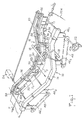
- the conveyor 10 illustrated as a whole in FIG. 1, comprises two parallel guides 12, 14 providing a free space E between them and cleared towards the top and the bottom.
- the guides define a path T for the cards, composed of several successive sections of different slopes.
- the path T begins at the right end of the figure with a short, substantially horizontal section T1 which the cards take from a machine (not shown) located upstream, typically a welding machine.
- the path T continues with a descending section T2 along which the cards pass through a prewash station 16 comprising ramps 18 for spraying solvent, shown diagrammatically, located both above and below the cards.
- the path then comprises a substantially horizontal section T3 along which the cards are immersed in a solvent bath, which has not been shown for reasons of clarity.
- the next section T4 is an ascending section along from which the cards pass through a final rinsing stage comprising solvent spray booms situated above and below the cards, not also shown.
- the journey ends in a short horizontal section T5, used for the output of the cards in the direction of a machine placed downstream, typically a machine for packaging printed circuit boards completed for transport, or even a machine automatic control, or in some cases a machine for applying a protective coating.
- a machine placed downstream typically a machine for packaging printed circuit boards completed for transport, or even a machine automatic control, or in some cases a machine for applying a protective coating.
- the printed circuit boards are driven and guided as such by the conveyor, thanks to the following provisions: the two guides 12, 14 have vertical guide surfaces 20 facing each other, spaced a distance slightly greater than the width of the cards, this distance being adjustable by means which will be described later.
- the cards are guided longitudinally by sliding their lateral edges along the guide guide surfaces.
- the two guides also comprise horizontal lower shoulders 22 of small width, on which the cards rest and progress by sliding along the lateral edges of their lower face.
- connection sections have a curved profile 24 in order to avoid sharp edges which are harmful to the progression of the cards and which risk damaging the edges of the cards.
- connection sections 26 with generally concave profile, such as for example between the horizontal section T3 and the two sections descending T2 and ascending T4, may follow a profile with one or more facets of intermediate slope, since during their progression , the cards 28 come into contact at this level with the lower shoulders 22 only via their lower edges frontal and posterior.
- the cards, thus guided, are driven by thrust members 30 engaging the rear edge of the cards.
- these thrust members are constituted by fingers driven by a chain 32 in closed loop driven by a motor not shown.
- the chain is mounted on one of the guides 12 and traverses a path with successive sections similar to those of the path of the cards, passing over a succession of toothed wheels 34 situated at the changes of slope.
- the chain 32 is disposed substantially under the guide 12 so as not to screen in the free space E between the guides.
- the fingers 30 project into this space but do not really constitute screens, in particular in the spraying stations since they are located behind the cards 28.
- they have the form of blades oriented parallel to the path T in order to present a practically negligible cross section with respect to the jets of sprayed solvent.
- the guides 12, 14 finally comprise means intended to oppose the detachment of the cards with respect to the lower shoulders 22.
- a first embodiment consists in providing an upper shoulder 36, opposite the lower shoulder 22 and spaced apart by a distance slightly greater than the thickness of the cards.
- This simple and inexpensive solution preferably applies to the straight path sections of a certain length. Indeed, it is not applicable to the initial and terminal parts of the sections in the vicinity of the slope changes since it must be taken into account that the maps deviate at least locally from the lower shoulders 22 in the slope change zones.
- this embodiment also allows effective washing of the lower lateral edges of the cards, in particular in the spray cleaning stations 16.
- a second embodiment consists in providing members 38 applying an elastic load to the upper lateral edges of the cards.
- these members may consist of elastic strips of small width, fixed at one end 38a to the guide 12, 14 above the lower shoulder 22 and the other end 38b of which comes into oblique elastic contact against the shoulder 22, so that the advancing cards 28 slightly raise the elastic blades placed successively along the guide 12, 14 by receiving from these blades 38 a weak force so as not to risk deforming the card but sufficient for s oppose the detachment of the card relative to the lower shoulder 22.
- This embodiment advantageously applies in areas of change of slope where certain parts of the card take off from the lower shoulder, that is to say at its ends as regards the changes of slope with a convex profile 24, for example between the section initial T1 and the descending section T2, that is to say at its center as regards the changes in slope with a concave profile, for example between the descending section T2 and the horizontal section T3.
- the peeling distance depends on the length of the cards and can reach large values, so that the elastic blades 38 must be flexible enough not to exert on the card excessive forces which would risk deforming and damaging it.
- This embodiment can also be applied in the descending section T2 where the cards risk sliding, by gravity, faster than the driving speed of the chain 32.
- the friction exerted by the blades 38 on the cards 28 will have a slowing effect.
- a third embodiment consists in fixing on the inner faces 20 of the guides 12, 14 ballast weights 40 of small width, fixed at the end of an arm 42 articulated on the guide, the ballast being situated behind the axis 44 by relative to the direction of movement of the cards.
- the ballast rests on the lower shoulder 22 by a rounded surface.
- a card raises the ballast 40 which thus rests on the upper lateral edge of the card 28 by preventing it from coming off the lower shoulder.
- weights 40 are close enough that the cards are always maintained, during their progress, by at least one ballast.
- this embodiment compared to the previous one, is that the ballast 40 applies in all circumstances a constant force on the card 28, whatever the height at which the card raises the ballast.
- this embodiment is preferably applied in the connection areas with concave profile 26, in which the central part deviates notably from the lower shoulder 22.
- an elastic blade 38 would apply an increasing force with the separation distance relative to the lower shoulder 22, which would risk damaging the cards of great length.
- the two guides 12, 14 can be separated or brought closer in order to allow the conveying of cards 28 of different widths.
- One of the guides 12 is fixedly mounted on the frame of machine, not shown, and the second guide 14 is mounted movable by means of several devices 46 with screw and nut with synchronized drive.
- the first and second devices 461, 462 are synchronized by a chain gear 48, as are the third 463 and fourth 464 devices, while the first 461 and fourth 464 are synchronized by gear shaft 50.
- One of the devices 481 comprises a centering member 52 which can be either manual, as illustrated, or motorized 54.
- control of the motor 54 can be either manual or automated, for example by programming on a keyboard the width of the card to pass, or by reading a code on a card appearing upstream of the conveyor.
- control unit will include all the safety devices necessary to avoid the modification of the spacing as long as a card is present in the conveyor.
- the fixed guide 12 will of course be the guide carrying the drive chain 32 of the card push fingers 30.
- the pushing fingers 30 will be arranged on the chain 32 with a pitch corresponding to the length of the cards 28 to be advanced in the conveyor.
- This placing in the active position 30a, or inactive position 30i, of the fingers can be carried out manually, or even automatically, by any appropriate means as will appear to the skilled person.
- the conveyor according to the present invention can be conveniently made in "double width" in order to simultaneously drive narrow cards from two production lines.
- a second guide adjustable in spacing will be placed on the other side of the fixed guide, this second guide and the fixed guide being provided with the same lateral guide surfaces, lower shoulders and means intended to oppose the detachment of the cards. as previously described.
- This variant within the immediate reach of those skilled in the art, has not been illustrated.
- the conveyor has a card introduction wheel 56 on the input section T1. This wheel is fixed to the fixed guide 12 along its inner face 20 and is driven at a tangential speed greater than the speed of progression of the chain 32.
- the spacing adjustment devices Depending on whether the cards driven on either side of the central fixed guide will have the same width, or different widths, provision will be made for the spacing adjustment devices to be common or not to the two adjustable guides.
- the conveyor comprises an extraction wheel 58 for the cards on the outlet section T5.
- This wheel is fixed on the fixed guide 12 along its inner face 20 and is driven at a tangential speed greater than the speed of progression of the chain 32.
Landscapes
- Engineering & Computer Science (AREA)
- Manufacturing & Machinery (AREA)
- Microelectronics & Electronic Packaging (AREA)
- Mechanical Engineering (AREA)
- Feeding Of Articles By Means Other Than Belts Or Rollers (AREA)
Applications Claiming Priority (2)
| Application Number | Priority Date | Filing Date | Title |
|---|---|---|---|
| FR8813659A FR2637879B1 (fr) | 1988-10-17 | 1988-10-17 | Convoyeur pour entrainement de cartes de circuits imprimes le long d'un trajet a pentes variables |
| FR8813659 | 1988-10-17 |
Publications (1)
| Publication Number | Publication Date |
|---|---|
| EP0365418A1 true EP0365418A1 (de) | 1990-04-25 |
Family
ID=9371101
Family Applications (1)
| Application Number | Title | Priority Date | Filing Date |
|---|---|---|---|
| EP89402859A Withdrawn EP0365418A1 (de) | 1988-10-17 | 1989-10-17 | Förderer zum Führen von gedruckten Leiterplatten längs einer Strecke mit wechselnder Neigung |
Country Status (2)
| Country | Link |
|---|---|
| EP (1) | EP0365418A1 (de) |
| FR (1) | FR2637879B1 (de) |
Cited By (3)
| Publication number | Priority date | Publication date | Assignee | Title |
|---|---|---|---|---|
| EP0562243A1 (de) * | 1992-03-25 | 1993-09-29 | DETEWE - DEUTSCHE TELEPHONWERKE Aktiengesellschaft & Co. | Lotschwallschutzschienen für Leiterplatten |
| EP0477821A3 (de) * | 1990-09-25 | 1994-02-09 | Spea Srl | |
| WO2004096486A1 (fr) * | 2003-05-01 | 2004-11-11 | Ismeca Semiconductor Holding Sa | Dispositif d'entrainement de bande permettant le conditionnement conditionnement de composants electroniques, dispositif et methode de mise en bande de composants electroniques. |
Families Citing this family (1)
| Publication number | Priority date | Publication date | Assignee | Title |
|---|---|---|---|---|
| DE4305042C1 (de) * | 1993-02-18 | 1994-05-26 | Siemens Ag | Vorrichtung zum Weitertransport von Leiterplatten |
Citations (3)
| Publication number | Priority date | Publication date | Assignee | Title |
|---|---|---|---|---|
| DE3328091C1 (de) * | 1983-08-03 | 1984-09-20 | Gerhard Ing.(grad.) 8012 Ottobrunn Knollmann | Verfahren und Vorrichtung zum kontinuierlichen Reinigen von bestückten, gedruckten Schaltungen und dergleichen |
| DE3318614A1 (de) * | 1983-05-21 | 1984-11-22 | Standard Elektrik Lorenz Ag, 7000 Stuttgart | Vorrichtung zum loesen von leiterplatten aus dem stanzgitter |
| EP0204609A1 (de) * | 1985-05-28 | 1986-12-10 | Outillages Scientifiques Et De Laboratoires O.S.L. | Reinigungsvorrichtung für elektronische Elemente und/oder für Teile der Feinmechanik |
-
1988
- 1988-10-17 FR FR8813659A patent/FR2637879B1/fr not_active Expired - Fee Related
-
1989
- 1989-10-17 EP EP89402859A patent/EP0365418A1/de not_active Withdrawn
Patent Citations (3)
| Publication number | Priority date | Publication date | Assignee | Title |
|---|---|---|---|---|
| DE3318614A1 (de) * | 1983-05-21 | 1984-11-22 | Standard Elektrik Lorenz Ag, 7000 Stuttgart | Vorrichtung zum loesen von leiterplatten aus dem stanzgitter |
| DE3328091C1 (de) * | 1983-08-03 | 1984-09-20 | Gerhard Ing.(grad.) 8012 Ottobrunn Knollmann | Verfahren und Vorrichtung zum kontinuierlichen Reinigen von bestückten, gedruckten Schaltungen und dergleichen |
| EP0204609A1 (de) * | 1985-05-28 | 1986-12-10 | Outillages Scientifiques Et De Laboratoires O.S.L. | Reinigungsvorrichtung für elektronische Elemente und/oder für Teile der Feinmechanik |
Cited By (3)
| Publication number | Priority date | Publication date | Assignee | Title |
|---|---|---|---|---|
| EP0477821A3 (de) * | 1990-09-25 | 1994-02-09 | Spea Srl | |
| EP0562243A1 (de) * | 1992-03-25 | 1993-09-29 | DETEWE - DEUTSCHE TELEPHONWERKE Aktiengesellschaft & Co. | Lotschwallschutzschienen für Leiterplatten |
| WO2004096486A1 (fr) * | 2003-05-01 | 2004-11-11 | Ismeca Semiconductor Holding Sa | Dispositif d'entrainement de bande permettant le conditionnement conditionnement de composants electroniques, dispositif et methode de mise en bande de composants electroniques. |
Also Published As
| Publication number | Publication date |
|---|---|
| FR2637879B1 (fr) | 1991-04-12 |
| FR2637879A1 (fr) | 1990-04-20 |
Similar Documents
| Publication | Publication Date | Title |
|---|---|---|
| EP0050080A2 (de) | Montage- und/oder Bearbeitungsanlage für Werkstücke, welche durch laufende und arrettierbare Werkstückträger getragen werden | |
| FR2832654A1 (fr) | Dispositif pour le tri de colis par separation morphologique | |
| EP1560772B1 (de) | Vorrichtung zum übertragen von in reihen ausgerichteten artikeln | |
| FR2531046A1 (fr) | Dispositif pour elargir et ralentir un flot de bouteilles debout, ou analogues | |
| BE1004127A3 (fr) | Procede et dispositif pour l'amenee de bouteilles ou recipients analogues. | |
| EP0365418A1 (de) | Förderer zum Führen von gedruckten Leiterplatten längs einer Strecke mit wechselnder Neigung | |
| EP0993877B1 (de) | Station zur visuellen Untersuchung von Früchten | |
| FR2819497A1 (fr) | Installation pour la circulation de palettes porte-pieces et palette pour cette installation | |
| FR2964958A1 (fr) | Dispositif de convoyage a galets et profile de guidage en ligne lateral specialement destine a un tel dispositif. | |
| EP0238430A1 (de) | Vorrichtung zum Aufbereiten von Chicorée und ähnlichen Gemüsen | |
| FR2695922A3 (fr) | Unité de trimodulaire pour convoyeurs. | |
| WO1989000524A1 (fr) | Systeme de manutention a luges | |
| FR2714315A1 (fr) | Dispositif de tri dimensionnel de déchets. | |
| FR2494236A1 (fr) | Installation de transport et de tri de colis | |
| FR2733491A1 (fr) | Dispositif de sortie d'exemplaires imprimes d'un dispositif a roues a aubes | |
| EP0323953A1 (de) | Handhabungssystem zum schnellen fördern von schlittenträgern | |
| FR2594811A1 (fr) | Convoyeur a chaines comportant des moyens pour empecher les pieces transportees de venir en contact | |
| FR2548647A1 (fr) | Dispositif de manutention automatique de charges ou d'articles divers | |
| FR2545398A1 (fr) | Installation pour l'assemblage et/ou l'usinage de pieces portees par des palettes circulantes et immobilisables | |
| EP1220807A1 (de) | Fördervorrichtung für hohl-verpackungen in einer automatischen behandlungsstrasse | |
| FR2515154A1 (fr) | Appareil extracteur a pales pour prelever des materiaux stockes en vrac | |
| FR2512723A1 (fr) | Installation pour l'assemblage et/ou l'usinage de pieces portees par des palettes circulantes et immobilisables | |
| FR2711977A1 (fr) | Dispositif de répartition d'articles entre deux lignes de convoyage respectivement simple ou multiple. | |
| FR2503014A1 (fr) | Dispositif de chargement automatique de pieces de bois, notamment dans une installation de sciage | |
| FR2661862A1 (fr) | Procede et machine pour decouper en lamelles dans la meme orientation des produits varies, tels que des champignons. |
Legal Events
| Date | Code | Title | Description |
|---|---|---|---|
| PUAI | Public reference made under article 153(3) epc to a published international application that has entered the european phase |
Free format text: ORIGINAL CODE: 0009012 |
|
| AK | Designated contracting states |
Kind code of ref document: A1 Designated state(s): AT BE CH DE ES GB GR IT LI LU NL SE |
|
| STAA | Information on the status of an ep patent application or granted ep patent |
Free format text: STATUS: THE APPLICATION IS DEEMED TO BE WITHDRAWN |
|
| 18D | Application deemed to be withdrawn |
Effective date: 19901026 |