EP0365435A2 - Système de transmission multicanal applicable dans une automobile - Google Patents
Système de transmission multicanal applicable dans une automobile Download PDFInfo
- Publication number
- EP0365435A2 EP0365435A2 EP89402905A EP89402905A EP0365435A2 EP 0365435 A2 EP0365435 A2 EP 0365435A2 EP 89402905 A EP89402905 A EP 89402905A EP 89402905 A EP89402905 A EP 89402905A EP 0365435 A2 EP0365435 A2 EP 0365435A2
- Authority
- EP
- European Patent Office
- Prior art keywords
- multiplex transmission
- units
- sending
- circuit
- transmission system
- Prior art date
- Legal status (The legal status is an assumption and is not a legal conclusion. Google has not performed a legal analysis and makes no representation as to the accuracy of the status listed.)
- Granted
Links
- 230000005540 biological transmission Effects 0.000 title claims abstract description 122
- 230000008054 signal transmission Effects 0.000 description 9
- 230000002411 adverse Effects 0.000 description 2
- 238000010586 diagram Methods 0.000 description 2
- 230000007257 malfunction Effects 0.000 description 2
- 230000000694 effects Effects 0.000 description 1
- 230000035939 shock Effects 0.000 description 1
Images

Classifications
-
- B—PERFORMING OPERATIONS; TRANSPORTING
- B60—VEHICLES IN GENERAL
- B60R—VEHICLES, VEHICLE FITTINGS, OR VEHICLE PARTS, NOT OTHERWISE PROVIDED FOR
- B60R16/00—Electric or fluid circuits specially adapted for vehicles and not otherwise provided for; Arrangement of elements of electric or fluid circuits specially adapted for vehicles and not otherwise provided for
- B60R16/02—Electric or fluid circuits specially adapted for vehicles and not otherwise provided for; Arrangement of elements of electric or fluid circuits specially adapted for vehicles and not otherwise provided for electric constitutive elements
- B60R16/03—Electric or fluid circuits specially adapted for vehicles and not otherwise provided for; Arrangement of elements of electric or fluid circuits specially adapted for vehicles and not otherwise provided for electric constitutive elements for supply of electrical power to vehicle subsystems or for
- B60R16/0315—Electric or fluid circuits specially adapted for vehicles and not otherwise provided for; Arrangement of elements of electric or fluid circuits specially adapted for vehicles and not otherwise provided for electric constitutive elements for supply of electrical power to vehicle subsystems or for using multiplexing techniques
-
- H—ELECTRICITY
- H04—ELECTRIC COMMUNICATION TECHNIQUE
- H04L—TRANSMISSION OF DIGITAL INFORMATION, e.g. TELEGRAPHIC COMMUNICATION
- H04L12/00—Data switching networks
- H04L12/02—Details
- H04L12/10—Current supply arrangements
-
- H—ELECTRICITY
- H04—ELECTRIC COMMUNICATION TECHNIQUE
- H04L—TRANSMISSION OF DIGITAL INFORMATION, e.g. TELEGRAPHIC COMMUNICATION
- H04L12/00—Data switching networks
- H04L12/28—Data switching networks characterised by path configuration, e.g. LAN [Local Area Networks] or WAN [Wide Area Networks]
- H04L12/40—Bus networks
- H04L12/40006—Architecture of a communication node
-
- B—PERFORMING OPERATIONS; TRANSPORTING
- B60—VEHICLES IN GENERAL
- B60R—VEHICLES, VEHICLE FITTINGS, OR VEHICLE PARTS, NOT OTHERWISE PROVIDED FOR
- B60R16/00—Electric or fluid circuits specially adapted for vehicles and not otherwise provided for; Arrangement of elements of electric or fluid circuits specially adapted for vehicles and not otherwise provided for
- B60R16/02—Electric or fluid circuits specially adapted for vehicles and not otherwise provided for; Arrangement of elements of electric or fluid circuits specially adapted for vehicles and not otherwise provided for electric constitutive elements
- B60R16/03—Electric or fluid circuits specially adapted for vehicles and not otherwise provided for; Arrangement of elements of electric or fluid circuits specially adapted for vehicles and not otherwise provided for electric constitutive elements for supply of electrical power to vehicle subsystems or for
- B60R16/0315—Electric or fluid circuits specially adapted for vehicles and not otherwise provided for; Arrangement of elements of electric or fluid circuits specially adapted for vehicles and not otherwise provided for electric constitutive elements for supply of electrical power to vehicle subsystems or for using multiplexing techniques
- B60R2016/0322—Temporary code for documents to be reclassified to G08C, H04L or H04Q
-
- H—ELECTRICITY
- H04—ELECTRIC COMMUNICATION TECHNIQUE
- H04L—TRANSMISSION OF DIGITAL INFORMATION, e.g. TELEGRAPHIC COMMUNICATION
- H04L12/00—Data switching networks
- H04L12/28—Data switching networks characterised by path configuration, e.g. LAN [Local Area Networks] or WAN [Wide Area Networks]
- H04L12/40—Bus networks
- H04L2012/40267—Bus for use in transportation systems
- H04L2012/40273—Bus for use in transportation systems the transportation system being a vehicle
-
- Y—GENERAL TAGGING OF NEW TECHNOLOGICAL DEVELOPMENTS; GENERAL TAGGING OF CROSS-SECTIONAL TECHNOLOGIES SPANNING OVER SEVERAL SECTIONS OF THE IPC; TECHNICAL SUBJECTS COVERED BY FORMER USPC CROSS-REFERENCE ART COLLECTIONS [XRACs] AND DIGESTS
- Y02—TECHNOLOGIES OR APPLICATIONS FOR MITIGATION OR ADAPTATION AGAINST CLIMATE CHANGE
- Y02D—CLIMATE CHANGE MITIGATION TECHNOLOGIES IN INFORMATION AND COMMUNICATION TECHNOLOGIES [ICT], I.E. INFORMATION AND COMMUNICATION TECHNOLOGIES AIMING AT THE REDUCTION OF THEIR OWN ENERGY USE
- Y02D30/00—Reducing energy consumption in communication networks
- Y02D30/50—Reducing energy consumption in communication networks in wire-line communication networks, e.g. low power modes or reduced link rate
Definitions
- the present invention relates to multipath transmission systems used for sending and receiving multiple signals between units which have a multiplex transmission function and are arranged in automobiles.
- One such multipath transmission system comprises a plurality of multiplex transmission units having a multipath transmission function.
- Each of the multiplex transmission units is located at a predetermined position within automobiles.
- the multiplex transmission units serve to collectively control device groups.
- one device group includes windshield wipers, power windows, door lock, etc.
- another device group includes various meters, warning lamp, indicators, etc.
- the individual units are connected to a common multiplex transmission path or so-called bus. Therefore, the transmission of multiple signals between the multiplex transmission units is performed through the bus to control the device groups.
- the aforementioned multiplex transmission units each include a sending/receiving device for sending and receiving the multiple signals toward or from the bus.
- the sending circuit of the sending/receiving device is formed of a switching circuit having an npn transistor, a pnp transistor, and a bias resistor. This switching circuit is connected to a corresponding line of the bus, and serves to adjust the potential on the line to one of two predetermined values, for example, 0 or 5 V, when the transistor is turned on or off.
- the multipath transmission system may be provided additionally with a limiter circuit for limiting the current of the transistors. In this case, however, the signal levels produced on the bus becomes too small to transmit the multiple signals.
- the aforementioned circumstances should be taken into consideration. More specifically, automobiles of the same model may be furnished with different meters or devices, that is, they may be different in grade.
- the difference in grade may possibly result in variation of the number of multiples transmission units connected to the bus. If the number of transmission units varies, then the current of the transistors in the sending circuits changes considerably during the multiple signal transmission, as mentioned before. Such a change of the current constitutes a hindrance to secure multiple signal transmission.
- the present invention has been contrived in consideration of these circumstances, and its object is to provide a multipath transmission system adapted for use in automobiles, in which multiple signals can be securely transmitted without any adverse effects attributable to a change of the number of multiplex transmission units connected to a multiplex transmission path.
- a multipath transmission system which comprises: a common multiplex transmission path; a plurality of multiplex transmission units connected in parallel with each other to the multiplex transmission path, each of the multiplex transmission units including a sending circuit for sending multiple signals from one of several groups in which various devices attached to an automobile are classified, to the multiplex transmission path; power supply means capable of applying electric power to the sending circuits of the individual multiplex transmission units, and adapted to always apply electric power to the sending circuit of at least one of the multiplex transmission units; and a bias circuit provided only in the multiplex transmission unit to which the electric power is always applied by the power supply means, and adapted to set the potential of the multiple signals on the multiplex transmission path when the multiple signals are supplied from the sending circuit of any multipath transmission unit to the multiplex transmission path.
- the bias circuit for setting the voltage level of the multiple signals supplied to the multiplex transmission path is incorporated only in the multiplex transmission unit to be always supplied with the electric power. Therefore, even if a multiplex transmission unit including no bias circuit is additionally connected to the multiplex transmission path, or if any connected unit without the bias circuit is removed from the transmission path, the voltage level of the multiple signals supplied from the individual transmission units to the transmission path cannot be changed. In consequence, the multiplex transmission units can equally transmit the multiple signals, thus ensuring higher reliability of signal transmission.
- the multiplex transmission unit with the bias circuit therein should be one associated with the group of devices which are regularly attached to automobiles, and the units with the bias circuit should be at least two in number.
- the multiplex transmission units including the bias circuit correspond to the groups of devices regularly attached to the automobiles, they can be reduced in number with respect to the whole multipath transmission system. Moreover, the signal transmission cannot be adversely affected by a change, if any, of the number of multiplex transmission units connected to the multiplex transmission path, which are attributable to the variation of the grade of the automobiles.
- the multiplex transmission units with the bias circuit are at least two in number, furthermore, the whole multipath transmission system cannot immediately suffer malfunction even when one of these units is in trouble. Thus, the reliability and safety of the signal transmission can be improved.
- the multipath transmission system 12 comprises a plurality of multiplex transmission units, e.g., first to fifth multiplex transmission units 13 to 17 (hereinafter referred to simply as first to fifth units).
- the first and fourth units 13 and 16, among these first to fifth units 13 to 17, are associated individually with groups of various fundamental meters and devices regularly attached to the automobile. More specifically, first unit 13 serves to collectively control one of groups of those devices which can be operated with relatively low power, such as windshield wipers, power windows, door locks, etc.
- the fourth unit 16 serves to send data signals as multiple signals from another group of the various meters, indicators and caution-advisory lamps.
- the second and third units 14 and 15 are associated with groups of those devices which can operate in response to the key position of an ignition switch (not shown) of the automobile.
- the fifth unit 17 is associated with a group of optional parts or devices that are optionally attached to the automobile according to users' preference. Therefore, the automobile is not always furnished with the fifth unit 17 and the device group associated therewith.
- the first to fifth units 13 to 17 are connected to a common multiplex transmission path, i.e., a so-called bus 18.
- Fig. 1 indicates the advancing direction of the automobile.
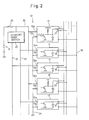
- FIG. 2 there is shown a specific configuration of the multipath transmission system of Fig. 1.
- Power supply terminals 13a and 16a of the first and fourth units 13 and 16 are connected to a feed line 20, which is connected directly to a power source 21.
- Power supply terminals 14a and 17a of the second and seventh units 14 and 17 are connected to a feed line 22, and power supply terminals 15a of the third unit 15 are connected to a feed line 23.
- Earth terminals 13b, 14b, 15b, 16b and 17b of the units 13 to 17 are grounded by means of an earth line 24.
- the feed lines 22 and 23 are connected to the feed line 20 through a changeover switch 25.
- the switch 25 is shifted in accordance with the key position of the ignition switch, thereby connecting or disconnecting the feed lines 22 and 23 to or from the power source 21.
- the feed line 20 is provided with a fuse 26 on the power-source side.
- the first to fifth units 13 to 17 each include sending circuits and receiving circuits for sending or receiving multiple signals to or from the corresponding groups of devices through the bus 18. These sending and receiving circuits are shown only schematically.
- each sending circuit is formed of a switching circuit including npn transistors.
- Fig. 2 only one npn transistor T13 is shown as being included in the switching circuit of the first unit 13, for simplicity of illustration.
- This transistor T13 cooperates with one of the devices in the device group associated with the first unit 13, so that the transistor T13 can be turned on or off in accordance with an input signal from the device concerned.
- the emitter of the transistor T13 is grounded, while its collector is connected to one of several input/output terminals 27 of the first unit 13. This input/output terminal 27 is connected to one line of the bus 18.
- the receiving circuit paired with the sending circuit or the transistor T13 includes an inverter I13 which is connected in parallel with the transistor T13.
- the input terminal of the inverter I13 is connected to a node between the transistor T13 and the input/output terminal 27. This receiving circuit cooperates with the corresponding device.
- the other devices associated therewith are also connected to their corresponding input/output terminals 27 through sending and receiving circuits similar to the aforementioned ones.
- the terminals 27 are connected to their corresponding lines of the bus 18.
- the sending circuits and the receiving circuits of the second to fifth units 14 to 17 have the same circuit configuration as those of the first unit 14. Therefore, the transistors and inverters of the second to fifth units 14 to 17, which correspond to those of the first unit 13, are designated by the same symbols for their counterparts of the first unit 13 except for postfixed numerals that are identical with the reference numerals for their corresponding units, and a description of those similar parts is omitted herein.
- Numerals 28, 29, 30 and 31 denote input/output terminals of the second, third, fourth, and fifth units 14, 15, 16 and 17, respectively.
- a bias circuit is further provided with each of those units which are continually connected to the power source 21 without regard to the shift position of the changeover switch 25, that is, the first and fourth units 13 and 16 that are associated with the groups of those devices which are regularly attached to the automobile, irrespective of the grade thereof.
- the bias circuit is represented by a load resistor R1, which is connected at one end to the collector of the transistor T13 as shown in Fig. 2, and is continually connected at the other end to the power source 21.
- the bias circuit of the fourth unit 16 is represented by a load resistor R2 which is similar to the resistor R1 of the first unit 13.
- the respective resistance values of the load resistors R1 and R2 are set so that current flowing through the collector of the transistor T of each sending circuit, i.e., collector current, has a proper value when the multiple signals are transmitted between the units through the bus 18.
- the multipath transmission system 12 comprises the five units.
- these new units should be ones which include no bias circuit, that is, units having the same circuit configuration as the units 14, 15 and 17.
- automobiles of the same model may be furnished with different devices, depending on their grades or users' option. Therefore, those multiplex transmission units which are associated with some device groups may or may not be added to the system 12, depending on whether the automobile is furnished with those optional devices. If the automobile is furnished with any other device groups than regular device groups, the transmission units for these optional device groups should be ones similar to the units 14, 15 and 17, as mentioned before.
- the bias circuits are included in the two units, i.e., the first and fourth units 13 and 16, so that the whole transmission system 12 cannot immediately suffer malfunction even if the bias circuit of one unit is in trouble.
- the first unit 13 which includes the bias circuit, among the first to fifth units 13 to 17, gets ready to be used for the transmission of multiple signals, that is, when the transistor T13 of the first unit 13 is turned on, a predetermined collector current flows into the collector of the transistor T13 through a power circuit defined by the power source 21, the load resistors R1 and R2 in the first and fourth units 13 and 16, respectively, and the corresponding lines of the bus 18.
- the voltage produced by the collector current flow through the load resistor R1, to be supplied from the input/output terminal 27 of the first unit 13 to the corresponding line of the bus 18, is about 0 V.
- the transistor T13 is turned off. Thereupon, no current flows through the load resistor R1, so that the voltage supplied from the input/output terminal 27 of the first unit 13 to the corresponding line of the bus 18 is about 5 V.
- the potential on the line of the bus 18 associated with the transistor T13 is shifted to about 0 or 5 V, and the resulting voltage signal or the multiple signals are transmitted toward the other units through the bus 18.
- a transistor T16 is turned on or off, by cooperating with the power circuit defined by the power source 21, the load resistors R1 and R2 in the first and fourth units 13 and 16, respectively, and the corresponding lines of the bus 18, just as in the aforementioned case. Thereupon, the voltages of the bus lines corresponding to the input/output terminals 30 are changed, and the resulting voltage signals or the multiple signals are transmitted to the other units through the bus 18. Also in the case of the fourth unit 16, moreover, the fourth unit can receive the multiple signals from the other units through the receiving circuits thereof.
- those other units than the first and fourth units 13 and 16, e.g., the second and fifth units 14 and 17, which include no bias circuit, may be also connected to the power source 21.
- the second unit 14 is enabled to transmit the multiple signals, for example, the transistor T14 is turned on or off by cooperating with the aforesaid power circuit, and the multiple signals can be transmitted from the second unit 14 to the other units through the bus 18.
- the other units i.e., the third and fifth units 15 and 17, can be used to transmit the multiple signals in the same manner as aforesaid.
- the individual units when the individual units are enabled to transmit the multiple signals, their sending circuits are connected to the same power circuit, without regard to the shift position of the changeover switch 25 or the change of the number of units connected to the bus 18.
- the individual units equally serve to transmit the multiple signals.
- the present invention is not limited to the multipath transmission system 12 according to the first embodiment described above.
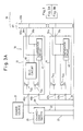
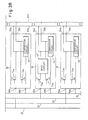
- Fig. 3 there is shock a multipath transmission system 32 according to a second embodiment.
- the multipath transmission system 32 comprises five units 33, 34, 35, 36 and 37, which correspond to the first to fifth units 13, 14, 15, 16 and 17, respectively.
- the sending circuit of the unit 33 is formed of a combination of a switching circuit including a pnp transistor 33a and a switching circuit including an npn transistor T33b.
- two input/output terminals 38a and 38b are assigned to the one sending circuit.
- These input/output terminals 38a and 38b are connected individually to specific lines of a bus 39.
- the bus lines corresponding to the one sending circuit are formed of a twisted pair wire. Only one twisted pair wire is shown in Fig. 3.
- a receiving circuit associated with the one sending circuit includes a comparator circuit 41 which is used to compare the voltages of two transmission lines 40a and 40b of its corresponding twisted pair wire 40.
- the other units 34 to 37 also each comprise sending and receiving circuits similar to those of the unit 33.
- sending circuits include a pair of transistors T34a and T34b; T35a and T35b; T36a and T36b; or T37a and T37b, respectively, and receiving circuits associated with the sending circuits include a comparator circuit 42, 43, 44 or 45, respectively.
- the units 33 and 36 of the second embodiment which correspond to the first and fourth units 13 and 16 of the first embodiment, respectively, incorporate bias circuits 46 and 47, respectively.
- These bias circuits 46 and 47 serve not only to supply a specific voltage signal to both transmission lines of each corresponding twisted pair wire, in response to the on-off operations of their corresponding pairs of transistors, when one of the units is ready to transmit the multiple signals, but also to protect the sending and receiving circuits of the units in case of any trouble in the feed lines or transmission lines.
- numerals 46a and 46b; 47a and 47b; 48a and 48b; 49a and 49b; and 50a and 50b denote power supply terminals and earth terminals of the units 33, 34, 35, 36 and 37, respectively, while numerals 51a and 51b; 52a and 52b; 53a and 53b; and 54a and 54b denote input/output terminals of the units 34 to 37, respectively, which are similar to the input/output terminals 38a and 38b of the unit 33.
- the multipath transmission system 32 of the second embodiment described above has the same function as the system 12 of the first embodiment. Unlike the first embodiment, however, the second embodiment uses the twisted pair wires for the signal transmission. With the arrangement of the second embodiment, therefore, the redundancy of the signal transmission can be improved to ensure satisfactory reliability in the signal transmission.
Landscapes
- Engineering & Computer Science (AREA)
- Computer Networks & Wireless Communication (AREA)
- Signal Processing (AREA)
- Mechanical Engineering (AREA)
- Small-Scale Networks (AREA)
- Dc Digital Transmission (AREA)
- Selective Calling Equipment (AREA)
Applications Claiming Priority (2)
| Application Number | Priority Date | Filing Date | Title |
|---|---|---|---|
| JP63264040A JP2713436B2 (ja) | 1988-10-21 | 1988-10-21 | 多重伝送路のバイアス回路設置方式 |
| JP264040/88 | 1988-10-21 |
Publications (3)
| Publication Number | Publication Date |
|---|---|
| EP0365435A2 true EP0365435A2 (fr) | 1990-04-25 |
| EP0365435A3 EP0365435A3 (fr) | 1992-09-02 |
| EP0365435B1 EP0365435B1 (fr) | 1994-07-27 |
Family
ID=17397715
Family Applications (1)
| Application Number | Title | Priority Date | Filing Date |
|---|---|---|---|
| EP89402905A Expired - Lifetime EP0365435B1 (fr) | 1988-10-21 | 1989-10-20 | Système de transmission multicanal applicable dans une automobile |
Country Status (4)
| Country | Link |
|---|---|
| US (1) | US5119371A (fr) |
| EP (1) | EP0365435B1 (fr) |
| JP (1) | JP2713436B2 (fr) |
| DE (1) | DE68917076T2 (fr) |
Cited By (4)
| Publication number | Priority date | Publication date | Assignee | Title |
|---|---|---|---|---|
| EP0530472A1 (fr) * | 1991-08-03 | 1993-03-10 | Robert Bosch Gmbh | Système de multiplexage |
| EP0482951A3 (en) * | 1990-10-25 | 1993-03-31 | Pioneer Electronic Corporation | Method of and system for data communication in communication network on automobile |
| EP0917991A3 (fr) * | 1997-11-21 | 2000-11-08 | SUMITOMO WIRING SYSTEMS, Ltd. | Système de communication multiplexé de vehicule et méthode de fabrication |
| EP0618702A4 (fr) * | 1992-09-22 | 2003-02-12 | Furukawa Electric Co Ltd | Appareil pour transmissions multiples |
Families Citing this family (2)
| Publication number | Priority date | Publication date | Assignee | Title |
|---|---|---|---|---|
| JPH04305754A (ja) * | 1991-04-02 | 1992-10-28 | Furukawa Electric Co Ltd:The | 多重伝送方式 |
| JP2839054B2 (ja) * | 1991-08-12 | 1998-12-16 | 株式会社デンソー | 通信装置 |
Family Cites Families (6)
| Publication number | Priority date | Publication date | Assignee | Title |
|---|---|---|---|---|
| JPS51118903A (en) * | 1975-04-11 | 1976-10-19 | Mitsubishi Electric Corp | Information transmission system |
| NL191374C (nl) * | 1980-04-23 | 1995-06-16 | Philips Nv | Communicatiesysteem met een communicatiebus. |
| DE3402633A1 (de) * | 1984-01-26 | 1985-08-01 | Siemens AG, 1000 Berlin und 8000 München | Schaltungsanordnung zum anschalten eines teilnehmers an eine busleitung |
| US4860006A (en) * | 1986-06-05 | 1989-08-22 | Michael Barall | Heartbeat collision avoidance method and circuit |
| JPS63264040A (ja) * | 1987-04-22 | 1988-10-31 | オリンパス光学工業株式会社 | ビデオスコ−プシステム |
| US4939725A (en) * | 1987-11-30 | 1990-07-03 | Furukawa Electric Co., Ltd. | Multiplex transmission system |
-
1988
- 1988-10-21 JP JP63264040A patent/JP2713436B2/ja not_active Expired - Lifetime
-
1989
- 1989-10-18 US US07/423,988 patent/US5119371A/en not_active Expired - Lifetime
- 1989-10-20 DE DE68917076T patent/DE68917076T2/de not_active Expired - Fee Related
- 1989-10-20 EP EP89402905A patent/EP0365435B1/fr not_active Expired - Lifetime
Cited By (5)
| Publication number | Priority date | Publication date | Assignee | Title |
|---|---|---|---|---|
| EP0482951A3 (en) * | 1990-10-25 | 1993-03-31 | Pioneer Electronic Corporation | Method of and system for data communication in communication network on automobile |
| EP0530472A1 (fr) * | 1991-08-03 | 1993-03-10 | Robert Bosch Gmbh | Système de multiplexage |
| EP0618702A4 (fr) * | 1992-09-22 | 2003-02-12 | Furukawa Electric Co Ltd | Appareil pour transmissions multiples |
| EP0917991A3 (fr) * | 1997-11-21 | 2000-11-08 | SUMITOMO WIRING SYSTEMS, Ltd. | Système de communication multiplexé de vehicule et méthode de fabrication |
| US6327263B1 (en) | 1997-11-21 | 2001-12-04 | Harness System Technologies | On-vehicle multiplex communication system and manufacturing method thereof |
Also Published As
| Publication number | Publication date |
|---|---|
| EP0365435B1 (fr) | 1994-07-27 |
| JPH02112353A (ja) | 1990-04-25 |
| US5119371A (en) | 1992-06-02 |
| DE68917076T2 (de) | 1994-11-17 |
| EP0365435A3 (fr) | 1992-09-02 |
| DE68917076D1 (de) | 1994-09-01 |
| JP2713436B2 (ja) | 1998-02-16 |
Similar Documents
| Publication | Publication Date | Title |
|---|---|---|
| EP0529602B1 (fr) | Récepteur différentiel, tolérant les défauts de lignes | |
| US5617282A (en) | Data communication system | |
| EP0010882B1 (fr) | Circuit de commutation | |
| US6587968B1 (en) | CAN bus termination circuits and CAN bus auto-termination methods | |
| US5572658A (en) | Network interface | |
| US4220876A (en) | Bus terminating and decoupling circuit | |
| US5483517A (en) | Multiplex transmission apparatus | |
| JPS61196726A (ja) | 車輌等の電力供給装置 | |
| KR980700198A (ko) | 차량내에 설치가능한 기능 모듈용 회로장치(Circuitry for Function Modules Which can be Fitted in a Motor Vehicle) | |
| US5486817A (en) | Communication system for vehicle control system having presettable initial state | |
| US4453088A (en) | Multiplex system for steering wheel mounted switches | |
| US4797582A (en) | Bidirectional interface circuit having a unipolar port and a bipolar port for logic signals | |
| EP0365435B1 (fr) | Système de transmission multicanal applicable dans une automobile | |
| EP0143650A2 (fr) | Système de multiplexage pour véhicule | |
| GB2277618A (en) | Multiplexed data transmission for motor vehicle | |
| US5404498A (en) | Voltage setting apparatus in a multiplex transmission system | |
| KR20020008180A (ko) | 자동차용 데이터 전송 시스템 및 데이터 전송 방법 | |
| JP3649118B2 (ja) | マイコンの入力回路 | |
| JP3196569B2 (ja) | 負荷の制御装置 | |
| US5262683A (en) | Method for specifying operating characteristics of integrated circuits | |
| US20040148124A1 (en) | Bus station connection to a bus system for restraining means and/or sensors | |
| US6236547B1 (en) | Zener zapping device and zener zapping method | |
| JPS62196014A (ja) | 負荷制御方式 | |
| JPH0720186A (ja) | 電気回路の故障診断装置 | |
| JP2779661B2 (ja) | 負荷の異常検出装置 |
Legal Events
| Date | Code | Title | Description |
|---|---|---|---|
| PUAI | Public reference made under article 153(3) epc to a published international application that has entered the european phase |
Free format text: ORIGINAL CODE: 0009012 |
|
| AK | Designated contracting states |
Kind code of ref document: A2 Designated state(s): DE FR GB |
|
| 17P | Request for examination filed |
Effective date: 19901218 |
|
| PUAL | Search report despatched |
Free format text: ORIGINAL CODE: 0009013 |
|
| AK | Designated contracting states |
Kind code of ref document: A3 Designated state(s): DE FR GB |
|
| 17Q | First examination report despatched |
Effective date: 19930917 |
|
| GRAA | (expected) grant |
Free format text: ORIGINAL CODE: 0009210 |
|
| AK | Designated contracting states |
Kind code of ref document: B1 Designated state(s): DE FR GB |
|
| REF | Corresponds to: |
Ref document number: 68917076 Country of ref document: DE Date of ref document: 19940901 |
|
| ET | Fr: translation filed | ||
| PLBE | No opposition filed within time limit |
Free format text: ORIGINAL CODE: 0009261 |
|
| STAA | Information on the status of an ep patent application or granted ep patent |
Free format text: STATUS: NO OPPOSITION FILED WITHIN TIME LIMIT |
|
| 26N | No opposition filed | ||
| REG | Reference to a national code |
Ref country code: GB Ref legal event code: IF02 |
|
| PGFP | Annual fee paid to national office [announced via postgrant information from national office to epo] |
Ref country code: FR Payment date: 20021008 Year of fee payment: 14 |
|
| PGFP | Annual fee paid to national office [announced via postgrant information from national office to epo] |
Ref country code: GB Payment date: 20021016 Year of fee payment: 14 |
|
| PG25 | Lapsed in a contracting state [announced via postgrant information from national office to epo] |
Ref country code: GB Free format text: LAPSE BECAUSE OF NON-PAYMENT OF DUE FEES Effective date: 20031020 |
|
| GBPC | Gb: european patent ceased through non-payment of renewal fee |
Effective date: 20031020 |
|
| PG25 | Lapsed in a contracting state [announced via postgrant information from national office to epo] |
Ref country code: FR Free format text: LAPSE BECAUSE OF NON-PAYMENT OF DUE FEES Effective date: 20040630 |
|
| REG | Reference to a national code |
Ref country code: FR Ref legal event code: ST |
|
| PGFP | Annual fee paid to national office [announced via postgrant information from national office to epo] |
Ref country code: DE Payment date: 20051014 Year of fee payment: 17 |
|
| PG25 | Lapsed in a contracting state [announced via postgrant information from national office to epo] |
Ref country code: DE Free format text: LAPSE BECAUSE OF NON-PAYMENT OF DUE FEES Effective date: 20070501 |