EP0365487A2 - Arbeitstisch - Google Patents
Arbeitstisch Download PDFInfo
- Publication number
- EP0365487A2 EP0365487A2 EP89810785A EP89810785A EP0365487A2 EP 0365487 A2 EP0365487 A2 EP 0365487A2 EP 89810785 A EP89810785 A EP 89810785A EP 89810785 A EP89810785 A EP 89810785A EP 0365487 A2 EP0365487 A2 EP 0365487A2
- Authority
- EP
- European Patent Office
- Prior art keywords
- base frame
- work table
- table top
- members
- longitudinal
- Prior art date
- Legal status (The legal status is an assumption and is not a legal conclusion. Google has not performed a legal analysis and makes no representation as to the accuracy of the status listed.)
- Granted
Links
Images



Classifications
-
- A—HUMAN NECESSITIES
- A47—FURNITURE; DOMESTIC ARTICLES OR APPLIANCES; COFFEE MILLS; SPICE MILLS; SUCTION CLEANERS IN GENERAL
- A47B—TABLES; DESKS; OFFICE FURNITURE; CABINETS; DRAWERS; GENERAL DETAILS OF FURNITURE
- A47B21/00—Tables or desks for office equipment, e.g. typewriters, keyboards
- A47B21/06—Tables or desks for office equipment, e.g. typewriters, keyboards characterised by means for holding, fastening or concealing cables
-
- A—HUMAN NECESSITIES
- A47—FURNITURE; DOMESTIC ARTICLES OR APPLIANCES; COFFEE MILLS; SPICE MILLS; SUCTION CLEANERS IN GENERAL
- A47B—TABLES; DESKS; OFFICE FURNITURE; CABINETS; DRAWERS; GENERAL DETAILS OF FURNITURE
- A47B13/00—Details of tables or desks
- A47B13/003—Connecting table tops to underframes
-
- A—HUMAN NECESSITIES
- A47—FURNITURE; DOMESTIC ARTICLES OR APPLIANCES; COFFEE MILLS; SPICE MILLS; SUCTION CLEANERS IN GENERAL
- A47B—TABLES; DESKS; OFFICE FURNITURE; CABINETS; DRAWERS; GENERAL DETAILS OF FURNITURE
- A47B13/00—Details of tables or desks
- A47B13/02—Underframes
-
- A—HUMAN NECESSITIES
- A47—FURNITURE; DOMESTIC ARTICLES OR APPLIANCES; COFFEE MILLS; SPICE MILLS; SUCTION CLEANERS IN GENERAL
- A47B—TABLES; DESKS; OFFICE FURNITURE; CABINETS; DRAWERS; GENERAL DETAILS OF FURNITURE
- A47B17/00—Writing-tables
- A47B17/03—Writing-tables with substantially horizontally extensible or adjustable parts other than drawers, e.g. leaves
- A47B17/033—Writing-tables with substantially horizontally extensible or adjustable parts other than drawers, e.g. leaves with parts added to the original furniture to enlarge its surface
-
- A—HUMAN NECESSITIES
- A47—FURNITURE; DOMESTIC ARTICLES OR APPLIANCES; COFFEE MILLS; SPICE MILLS; SUCTION CLEANERS IN GENERAL
- A47B—TABLES; DESKS; OFFICE FURNITURE; CABINETS; DRAWERS; GENERAL DETAILS OF FURNITURE
- A47B17/00—Writing-tables
- A47B17/06—Writing-tables with parts, e.g. trays, movable on a pivot or by chains or belts
- A47B17/065—Pivotally mounted auxiliary tables
-
- A—HUMAN NECESSITIES
- A47—FURNITURE; DOMESTIC ARTICLES OR APPLIANCES; COFFEE MILLS; SPICE MILLS; SUCTION CLEANERS IN GENERAL
- A47B—TABLES; DESKS; OFFICE FURNITURE; CABINETS; DRAWERS; GENERAL DETAILS OF FURNITURE
- A47B21/00—Tables or desks for office equipment, e.g. typewriters, keyboards
- A47B21/06—Tables or desks for office equipment, e.g. typewriters, keyboards characterised by means for holding, fastening or concealing cables
- A47B2021/062—Tables or desks for office equipment, e.g. typewriters, keyboards characterised by means for holding, fastening or concealing cables the worksurface moving forward to expose the wire gutter, e.g. up and forward
-
- A—HUMAN NECESSITIES
- A47—FURNITURE; DOMESTIC ARTICLES OR APPLIANCES; COFFEE MILLS; SPICE MILLS; SUCTION CLEANERS IN GENERAL
- A47B—TABLES; DESKS; OFFICE FURNITURE; CABINETS; DRAWERS; GENERAL DETAILS OF FURNITURE
- A47B37/00—Tables adapted for other particular purposes
- A47B2037/005—Tables specially adapted for laboratories
-
- A—HUMAN NECESSITIES
- A47—FURNITURE; DOMESTIC ARTICLES OR APPLIANCES; COFFEE MILLS; SPICE MILLS; SUCTION CLEANERS IN GENERAL
- A47B—TABLES; DESKS; OFFICE FURNITURE; CABINETS; DRAWERS; GENERAL DETAILS OF FURNITURE
- A47B2200/00—General construction of tables or desks
- A47B2200/0011—Underframes
- A47B2200/0013—Desks with central bearing beams
-
- A—HUMAN NECESSITIES
- A47—FURNITURE; DOMESTIC ARTICLES OR APPLIANCES; COFFEE MILLS; SPICE MILLS; SUCTION CLEANERS IN GENERAL
- A47B—TABLES; DESKS; OFFICE FURNITURE; CABINETS; DRAWERS; GENERAL DETAILS OF FURNITURE
- A47B2200/00—General construction of tables or desks
- A47B2200/0035—Tables or desks with features relating to adjustability or folding
- A47B2200/004—Top adjustment
- A47B2200/0043—Inclination adjustable work top
-
- A—HUMAN NECESSITIES
- A47—FURNITURE; DOMESTIC ARTICLES OR APPLIANCES; COFFEE MILLS; SPICE MILLS; SUCTION CLEANERS IN GENERAL
- A47B—TABLES; DESKS; OFFICE FURNITURE; CABINETS; DRAWERS; GENERAL DETAILS OF FURNITURE
- A47B2200/00—General construction of tables or desks
- A47B2200/0084—Accessories for tables or desks
- A47B2200/0085—Supplementary support fixed on the edge of a desk or table
-
- A—HUMAN NECESSITIES
- A47—FURNITURE; DOMESTIC ARTICLES OR APPLIANCES; COFFEE MILLS; SPICE MILLS; SUCTION CLEANERS IN GENERAL
- A47B—TABLES; DESKS; OFFICE FURNITURE; CABINETS; DRAWERS; GENERAL DETAILS OF FURNITURE
- A47B2200/00—General construction of tables or desks
- A47B2200/0084—Accessories for tables or desks
- A47B2200/0086—Supplementary support fixed to the extension of a table leg
-
- A—HUMAN NECESSITIES
- A47—FURNITURE; DOMESTIC ARTICLES OR APPLIANCES; COFFEE MILLS; SPICE MILLS; SUCTION CLEANERS IN GENERAL
- A47B—TABLES; DESKS; OFFICE FURNITURE; CABINETS; DRAWERS; GENERAL DETAILS OF FURNITURE
- A47B2200/00—General construction of tables or desks
- A47B2200/0084—Accessories for tables or desks
- A47B2200/0088—Appliance support having rotary joint or articulated connection
Definitions
- the invention relates to a work table according to the preamble of claim 1, in particular to a work table constructed according to the modular principle.
- work tables of this type are suitable both as office furniture with a work or display surface and attachments and superstructures for storage trays or device support surfaces, as well as for laboratory workplaces in which both writing and storage surfaces are suitable for different work and examination processes are required.
- the object of the present invention is to provide a work table in which, starting from a base frame with foot and console elements for receiving a table top, and a number of optionally connectable to the base frame and / or laterally sash frame with its own foot elements and on the sash frame even buildable fixed or articulated storage areas are available.
- the base frame should be a unit with receiving areas for attaching cable and connection elements e.g. designed for electricity, telephone, etc.
- the advantage of the work table according to the invention can be seen in the extensive adaptability to individual requirements and to different workplaces. Due to the interchangeability of the hinged sash frame and various console elements on the base frame, the components of the work table can also be used according to the modular principle. A work table designed according to the invention is thus easily adaptable to different requirements.
- Fig. 1, 1 generally designates a base frame of the work table according to the invention, which frame consists of a front and a rear side member 2 and a left and a right cross member 3 each.
- These supports 2, 3 are preferably made of hollow profile bars and are expediently butt-connected to one another by welding.
- the hollow profile bars 2, 3 can be arranged lying in the same plane or can be connected to one another at the ends.
- the base frame 1 rests on support elements in the form of table legs 4 or one or two box bodies in the form of drawer sticks 5 (shown in broken lines) which are detachably connected to the base frame by means of screw connections 6.
- the base frame 1 On the base frame 1 are, in continuation of the cross member 3, relative to this pivotable casement 7, 7 'articulated.
- the coupling takes place by means of articulated connecting members 8 which can be inserted into the ends of the hollow profile rods and which are explained in more detail with reference to FIG. 2.
- the appropriately flying at corner points E of the base frame 1 coupled sash 7, 7 ' are also constructed from hollow profile bars and provided at their outer ends with support members 9, 9', which in turn rest on support elements, for example in the form of table legs 4.1 or box bodies 5.1.
- the table legs 4.1 or other supporting elements to be used in their place are expediently of the same shape as the supporting elements 4, 5 of the base frame 1, and how they are connected to the supporting members 9 by detachable screw connections 6.
- connection elements In order to equip the work table with all the supply lines for electrical current, telephone, compressed air, gas, etc. that are usually required on it, it can be provided with corresponding connection elements.
- 1 shows a connection set for electrical current with a fuse and switch box 10, a flexible cable guide 11 bridging the joint connecting members 8, a first distribution box 12 and a plug connector 13. All electrical devices to be arranged in the region of the base frame can be connected to the latter will.
- a corresponding connection set for in the area of the left wing frame 7 'to be arranged electrical devices can include a second distribution box 12' and a second connector strip 13 '.
- This tub 15 is suitably formed from sheet steel and can be designed with edge zones 16, 16 ', which cover the relevant sections of the longitudinal and / or cross members 2, 3.
- the plug connector 13 is expediently arranged in the interior of the tub.
- Fig. 2 shows schematically an embodiment of the articulated connecting members 8, 8 'for the pivotable connection of a casement 7, 7' to the base frame 1 in apart the drawn state.
- the connecting elements 8, 8 'shown as hinge elements are provided with connecting pins 17 inserted into the opening of the hollow frame profiles and secured therein by means of clamping elements 18. After the complementary hinge elements have been pushed together, they are locked against one another by a (self-locking) plug pin 19.
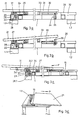
- the principle of coupling a table top 21 to the base frame 1 can be seen from FIGS. 3a and 3b.
- the latter On its side 1.1 facing the user, the latter has a perforated plate 22 with a number (five in FIG. 2a) of holes 23 which are arranged one above the other perpendicular to the plane of the frame and oriented parallel to the plane of the frame.
- the downward arm 26 of the pivot lever 24 contains a bore for receiving an extendable (not shown) plug pin next to its lower end. This is marked as a black circle in the drawing.
- a housing 27 containing the pivot lever 24 is supported on a support 28. This arrangement is of course present on both sides of the table top 21 or on the base frame as a mirror image.
- a bearing element 29 with a longitudinal slot guide 30, which has an upwardly open access opening 31, is placed on both sides thereof.
- These two bearing elements 29 can be connected to one another by a cross member 32 that extends across the width of the base frame 1.
- On the bottom of the table plate 21 are attached to the bearing elements 29 corresponding L-shaped locking bracket 33 which contain a number of holes 35 for receiving a (not shown) plug pin on its downward leg 34. This plug pin is intended to engage in the longitudinal slot guide 30, as shown in FIG. 3a by the marking with a black circle.
- Fig. 3a the position of the pivot lever 24 and the locking bracket 33 with the horizontal table top 21 and the lowest position thereof is shown in each case to the base frame 1.
- the plug pin black circle
- the plug pin marked there with a black circle would be inserted into a correspondingly deeper hole 35 in the leg 34 on the locking bracket 33.
- the height of the holes 23 and 35 is coordinated so that the table top can always be brought to a horizontal position.
- FIG. 3b shows the table top 21 in a position inclined towards the user.
- the position of the black marked spigot in the hole tab 22 and in the pivot lever 24 is the same as in Fig. 3a and the pivot lever housing 27 is supported on the support 28 as there.
- the black marked plug is inserted in the locking bracket 33 on the table side 1.2 facing away from the user in a lower one of the holes 35. Through the pin engagement in the longitudinal slot guide 30, the table top 21 is raised there.
- the table top 21 according to FIGS. 3c and 3d can be pulled off from both positions of FIGS. 3a and 3b against the user without moving away from the base frame 1 to solve.
- the swivel lever 24 is responsible for this.
- the table top 21 is pulled off in the direction of arrow P, it swivels around its bearings in the swivel lever housing 27 and on the perforated plate 22 in the counterclockwise direction until its knee 24.1 strikes the support 28.1.
- Fig. 4 shows the arrangement of a support surface or a table top 41 on a casement 7 '. At predetermined points, this contains a number of plug pins 42, the position of which corresponds to the arrangement of fitting bushes 43 on the underside of the support surface or table top 41.
- the fitting sleeves 43 are provided with laterally screw-in clamping screws 44, by means of which the bearing surface or table top 41 is fixed after the plugging of the fitting sleeves 43 onto the plug pin 42 on the casement 7 '.
- Fig. 7 shows a double base frame in a schematic representation for the accommodation of two table tops 53 on the same support plane.
- an assembly zone 52 is indicated, in which any structures, for example in the manner shown in FIG. 8, can be arranged.
- FIG 8 shows a work table with two table tops 53, a central structure 54 and a body extension 55 which is attached to the double base frame of the work table (also not shown) by means of a sash frame (also not shown).
Landscapes
- Tables And Desks Characterized By Structural Shape (AREA)
- Electrical Discharge Machining, Electrochemical Machining, And Combined Machining (AREA)
- Legs For Furniture In General (AREA)
- Ladders (AREA)
- Pharmaceuticals Containing Other Organic And Inorganic Compounds (AREA)
- Hinges (AREA)
- Workshop Equipment, Work Benches, Supports, Or Storage Means (AREA)
- Vending Machines For Individual Products (AREA)
- Turbine Rotor Nozzle Sealing (AREA)
- Inorganic Insulating Materials (AREA)
Abstract
Description
- Die Erfindung bezieht sich auf einen Arbeitstisch nach dem Oberbegriff des Patentanspruchs 1, insbesondere auf einen nach dem Baukastenprinzip aufgebauten Arbeitstisch.
- Arbeitstische dieser Art eignen sich wegen ihrer Anpassbarkeit an sehr unterschiedliche Gebrauchsanforderungen sowohl als Bureaumöbel mit einer Arbeits- oder Auslagefläche und An- und Aufbauten für Ablagetablare oder Geräteauflageflächen, als auch für Laborarbeitsplätze, bei welchen sowohl Schreib- als auch Abstellflächen für unterschiedliche Arbeits- und Untersuchungsvorgänge gefordert sind.
- Die Aufgabe bei der vorliegenden Erfindung besteht darin einen Arbeitstisch zu schaffen, bei dem ausgehend von einem Basisrahmen mit Fuss- und Konsolelementen für die Aufnahme einer Tischplatte, und eine Anzahl wahlweise auf dem Basisrahmen und/oder seitlich davon anschliessbare Flügelrahmen mit eigenen Fusselementen und am Flügelrahmen selbst aufbaubaren fest oder gelenkig damit verbundenen Abstellflächen vorhanden sind. Dabei soll der Basisrahmen als Einheit mit Aufnahmebereichen für das Anbringen von Leitungs- und Anschlusselementen z.B. für elektrischen Strom, Telefon etc. gestaltet sein.
- Die erfindungsgemässe Lösung dieser Aufgabe ist durch die kennzeichnenden Merkmale des Patentanspruchs 1 definiert. Ausführungsformen davon gehen aus den abhängigen Ansprüchen hervor.
- Der Vorteil des erfindungsgemässen Arbeitstisches ist in der weitgehenden Anpassbarkeit an individuelle Anforderungen und an unterschiedliche Arbeitsplätze zu sehen. Durch die Austauschbarkeit von schwenkbar ankuppelbaren Flügelrahmen und diverser Konsolelemente am Basisrahmen sind die Bauteile des Arbeitstisches auch nach dem Baukastenprinzip einsetzbar. Damit ist ein erfindungsgemäss gestalteter Arbeitstisch leicht an unterschiedliche Anforderungen anpassbar.
- Details und Ausführungsvarianten des Erfindungsgegenstandes gehen aus der nachstehenden Beispielsbeschreibung anhand der Zeichnung hervor. Es zeigt
- Fig. 1 schematisch einen Basisrahmen in perspektivischer Darstellungsweise mit seitlich daran anschliessbaren Flügelrahmen,
- Fig. 1a einen Schnitt nach der Linie A-A in Fig. 1 zur Darstellung einer Einbauwanne im Basisrahmen, z.B. für die Unterbringung von Kleinmaterial und Werkzeug,
- Fig. 2 schematisch die Anschlussteile eines Flügelrahmens an den Basisrahmen
- Fig. 3a Details für die Montage der Tischplatte am Basisrahmen, und
- Fig. 3b die Möglichkeit der Schrägstellung der Tischplatte relativ zum Basisrahmen,
- Fig. 3c, 3d Darstellungen zur Erläuterung der Handhabung der Tischplatte am Basisrahmen,
- Fig. 4 die Anordnung einer Auflagefläche auf einem Flügelrahmen, mit aufgeklappter Auflagefläche,
- Fig. 5 schematisch eine Schwenkarmanordnung für Telefon- oder Monitortablare,
- Fig. 6 die Anordnung eines Tablar-Längsträgers am Basisrahmen,
- Fig. 7 einen Doppel-Basisrahmen für die Aufnahme von zwei Tischplatten, mit einem Mittelträger für die Stützung einer hochgesetzten Auflagefläche, und
- Fig. 8 eine perspektivische Darstellung eines Arbeitstisches mit zwei Tischplatten und einer mittleren hochgesetzten Auflagefläche.
- In Fig. 1 bezeichnet 1 allgemein einen Basisrahmen des erfindungsgemässen Arbeitstisches, welcher Rahmen aus einem vordern und einem hintern Längsträger 2 und je einem linken und einem rechten Querträger 3 besteht. Diese Träger 2, 3 sind vorzugsweise aus Hohlprofilstäben gestaltet und zweckmässig stumpf aufeinanderstehend durch Schweissung miteinander verbunden. Die Hohlprofilstäbe 2, 3 können in der gleichen Ebene liegend angeordnet oder an den Enden aufeinanderliegend miteinander verbunden sein.
- Der Basisrahmen 1 ruht auf Stützelementen in der Form von Tischbeinen 4 oder einem oder zwei Kastenkörpern in der Form von (strichliert gezeigten) Schubladenstöcken 5, die mittels Schraubverbindungen 6 mit dem Basisrahmen lösbar verbunden sind.
- An den Basisrahmen 1 sind, in Fortsetzung der Querträger 3, relativ zu diesem verschwenkbare Flügelrahmen 7, 7′ gelenkig ankuppelbar. Die Ankupplung erfolgt mittels in die Enden der Hohlprofilstäbe einsetzbaren Gelenk-Anschlussgliedern 8, die anhand der Fig. 2 näher erläutert sind. Die zweckmässig fliegend an Eckstellen E des Basisrahmens 1 angekuppelten Flügelrahmen 7, 7′ sind ebenfalls aus Hohlprofilstäben aufgebaut und an ihren äussern Enden mit Traggliedern 9, 9′ versehen, welche ihrerseits auf Stützelementen z.B. in der Form von Tischbeinen 4.1 oder Kastenkörpern 5.1 aufliegen. Die Tischbeine 4.1 bzw. andere an deren Stelle zu verwendende Stützelemente sind zweckmässig von gleicher Gestalt wie die Stützelemente 4, 5 des Basisrahmens 1, und wie diese durch lösbare Schraubverbindungen 6 mit den Traggliedern 9 verbunden.
- Um den Arbeitstisch mit allen üblicherweise an diesem notwendigen Zuleitungen für elektrischen Strom, Telefon, Druckluft, Gas etc. auszurüsten, kann dieser mit entsprechenden Anschlusselementen versehen sein. Fig. 1 zeigt diesbezüglich eine Anschlussgarnitur für elektrischen Strom mit einem Sicherungs- und Schaltkasten 10, einer die Gelenk-Anschlussglieder 8 überbrückenden flexiblen Kabelführung 11, einem ersten Verteilkasten 12 und einer Stekkerleiste 13. An letzterer können alle im Bereich des Basisrahmens anzuordnenden elektrischen Geräte angeschlossen werden. Eine entsprechende Anschlussgarnitur für im Bereich des linksseitigen Flügelrahmens 7′ anzuordnende elektrische Geräte kann einen zweiten Verteilkasten 12′ und eine zweite Steckerleiste 13′ umfassen.
- In Fig. 1a ist eine aus dem Schnitt A-A der Fig. 1 erkennbare, in den von den Längs- und Querträgern 2, 3 begrenzten Freiraum des Basisrahmens eingesetzte Wanne 15 zur Aufnahme von Betriebsmitteln wie Kabeln, Werkzeugen etc. schematisch dargestellt. Diese Wanne 15 ist zweckmässig aus Stahlblech geformt und kann mit Randzonen 16, 16′ ausgestaltet sein, welche die bezüglichen Abschnitte der Längs- und/oder Querträger 2, 3 abdecken. Die Steckerleiste 13 wird dabei zweckmässig im Innern der Wanne angeordnet.
- Fig. 2 zeigt schematisch eine Ausführungsform der Gelenkanschlussglieder 8, 8′ für den schwenkbaren Anschluss eines Flügelrahmens 7, 7′ an den Basisrahmen 1 in auseinan dergezogenem Zustand. Die als Scharnierelemente gezeigten Anschlussglieder 8, 8′ sind mit in die Oeffnung der Rahmen-Hohlprofile eingesetzten Anschlusszapfen 17 versehen und mittels Spannelementen 18 darin gesichert. Nach dem Zusammenschieben der komplementären Scharnierelemente werden diese durch einen (sich selbst sichernden) Steckzapfen 19 gegeneinander verriegelt.
- Der Basisrahmen 1 und die Flügelrahmen 7, 7′ dienen in erster Linie zur Aufnahme von Abstellflächen bzw. deren Tragelemente. Aus den Fig. 3a und 3b ist das Prinzip der Ankupplung einer Tischplatte 21 am Basisrahmen 1 ersichtlich. Dieser trägt auf seiner dem Benützer zugewandten Seite 1.1 eine Lochlasche 22 mit einer Anzahl (in Fig. 2a fünf) Löchern 23, die senkrecht zur Rahmenebene übereinander angeordnet und parallel zur Rahmenebene orientiert sind. Auf der Unterseite der Tischplatte 21 und der Lochlasche 22 gegenüberliegend ist ein abgewinkelter Schwenkhebel 24 auf einem Zapfen 25 in Gegenuhrzeigerrichtung gelagert. Der abwärtsgerichtete Arm 26 des Schwenkhebels 24 enthält nächst seinem untern Ende eine Bohrung zur Aufnahme eines ausziehbaren (nicht gezeigten) Steckzapfens. Dieser ist in der Zeichnung als schwarzer Kreis markiert. Ein den Schwenkhebel 24 enthaltendes Gehäuse 27 ist auf einer Auflage 28 gestützt. Diese Anordnung ist selbstverständlich beidseits der Tischplatte 21 bzw. am Basisrahmen spiegelbildlich vorhanden.
- Auf der dem Benützer abgewandten Seite 1.2 des Basisrahmens 1 sind beidseits davon je ein Lagerelement 29 mit einer Längsschlitzführung 30, die an ihrem Vorderende eine nach oben offene Zutrittsöffnung 31 aufweist, aufgesetzt. Diese beiden Lagerelemente 29 können durch ein über die Breite des Basisrahmens 1 reichendes Traversenelement 32 miteinander verbunden sein. Auf der Unterseite der Tisch platte 21 sind mit den Lagerelementen 29 korrespondierende L-förmige Rastbügel 33 befestigt, die an ihrem abwärtsgerichteten Schenkel 34 eine Anzahl Löcher 35 zur Aufnahme eines (nicht gezeigten) Steckzapfens enthalten. Dieser Steckzapfen ist dazu bestimmt, in die Längsschlitzführung 30 einzugreifen, wie Fig. 3a durch die Markierung mit einem schwarzen Kreis zeigt.
- In Fig. 3a ist die Stellung des Schwenkhebels 24 und des Rastbügels 33 bei horizontaler Tischplatte 21 und tiefster Position derselben jeweils zum Basisrahmen 1 dargestellt. Für den Fall, dass eine höhere Stellung der Tischplatte gewünscht wird, wäre am Schwenkhebel 24 der Steckzapfen (schwarzer Kreis) in ein höher gelegenes Loch 23 der Lochlasche 22 einzusetzen und dabei die Tischplatte 21 auf die gewünschte Höhe anzuheben. Gleichzeitig wäre am Rastbügel 33 der dort mit einem schwarzen Kreis gekennzeichnete Steckzapfen in ein entsprechend tieferes Loch 35 im Schenkel 34 einzusetzen. Die Höhenlage der Löcher 23 und 35 ist so aufeinander abgestimmt, dass die Tischplatte immer auf eine Horizontallage bringbar ist.
- Fig, 3b zeigt die Tischplatte 21 in gegen den Benützer hin geneigter Stellung. Die Stellung des schwarz markierten Steckzapfens in der Lochlasche 22 und im Schwenkhebel 24 ist gleich wie in Fig. 3a und das Schwenkhebelgehäuse 27 ist wie dort auf der Auflage 28 abgestützt. Anders dagegen ist der schwarz markierte Steckzapfen im Rastbügel 33 auf der dem Benützer abgewandten Tischseite 1.2 in einem tieferliegenden der Löcher 35 eingesetzt. Durch den Zapfeneingriff in der Längsschlitzführung 30 wird damit die Tischplatte 21 dort angehoben.
- Um einerseits das Umstecken der Steckzapfen der hinteren Lageranordnung 29/33 zu ermöglichen und andererseits die Wanne 15 und die Steckerleiste 13 zugänglich zu machen, ist die Tischplatte 21 gemäss den Fig. 3c und 3d aus beiden Stellungen der Fig. 3a und 3b gegen den Benützer hin abziehbar, ohne sich vom Basisrahmen 1 zu lösen. Hiefür ist der Schwenkhebel 24 verantwortlich, der sich beim Abziehen der Tischplatte 21 in Pfeilrichtung P um seine Lagerstellen im Schwenkhebelgehäuse 27 und an der Lochlasche 22 in Gegenuhrzeigerrichtung verschwenkt, bis sein Knie 24.1 an der Auflage 28.1 anschlägt.
- Fig. 4 zeigt die Anordnung einer Auflagefläche bzw. einer Tischplatte 41 auf einem Flügelrahmen 7′. Dieser enthält an vorgegebenen Stellen eine Anzahl Steckzapfen 42, deren Position mit der Anordnung von Passbüchsen 43 auf der Unterseite der Auflagefläche bzw. Tischplatte 41 übereinstimmt. Die Passbüchsen 43 sind mit seitlich einschraubbaren Klemmschrauben 44 versehen, mittels welchen die Auflagefläche bzw. Tischplatte 41 nach dem Aufstecken der Passbüchsen 43 auf den Steckzapfen 42 auf dem Flügelrahmen 7′ fixiert wird.
- In den Fig. 5 und 6 sind Anordnungen von Tischaufbauten gezeigt, wie sie auf dem Basisrahmen 1 direkt (Fig. 5), oder über eine Aufspannschiene 45 (Fig. 6) montiert sind. In beiden Fig. 5 und 6 sind gleiche schwenkbare Auflagetische 46 und 47 gezeigt, die jeweils mit angepassten Zusatzelementen 48, 49 auf den entsprechenden Montagebereichen befestigt sind.
- Fig. 7 zeigt einen Doppel-Basisrahmen in schematischer Darstellungsweise für die Aufnahme von zwei Tischplatten 53 auf derselben Stützebene. Im Stossbereich dieser beiden Tischplatten ist, gestützt durch einen Längsträger 51, eine Montagezone 52 angedeutet, in welcher allfällige Aufbauten, z.B. in der Art nach Fig. 8, angeordnet sein können.
- Die Fig. 8 zeigt einen Arbeitstisch mit zwei Tischplatten 53, einem Mittelaufbau 54 und einem Korpusanbau 55, der mittels eines (nicht gezeigten) Flügelrahmens an den (ebenfalls nicht gezeigten) Doppel-Basisrahmen des Arbeitstisches angebaut ist.
Claims (8)
Priority Applications (1)
| Application Number | Priority Date | Filing Date | Title |
|---|---|---|---|
| AT89810785T ATE98452T1 (de) | 1988-10-17 | 1989-10-16 | Arbeitstisch. |
Applications Claiming Priority (2)
| Application Number | Priority Date | Filing Date | Title |
|---|---|---|---|
| CH386388 | 1988-10-17 | ||
| CH3863/88 | 1988-10-17 |
Publications (3)
| Publication Number | Publication Date |
|---|---|
| EP0365487A2 true EP0365487A2 (de) | 1990-04-25 |
| EP0365487A3 EP0365487A3 (de) | 1991-01-30 |
| EP0365487B1 EP0365487B1 (de) | 1993-12-15 |
Family
ID=4265097
Family Applications (1)
| Application Number | Title | Priority Date | Filing Date |
|---|---|---|---|
| EP89810785A Expired - Lifetime EP0365487B1 (de) | 1988-10-17 | 1989-10-16 | Arbeitstisch |
Country Status (8)
| Country | Link |
|---|---|
| US (1) | US5078055A (de) |
| EP (1) | EP0365487B1 (de) |
| JP (1) | JPH02198777A (de) |
| AT (1) | ATE98452T1 (de) |
| AU (1) | AU624428B2 (de) |
| CA (1) | CA2000760A1 (de) |
| DE (2) | DE58906437D1 (de) |
| DK (1) | DK511989A (de) |
Cited By (1)
| Publication number | Priority date | Publication date | Assignee | Title |
|---|---|---|---|---|
| WO1999003373A3 (de) * | 1997-07-15 | 1999-04-08 | Joachim Niehaus | Drehgelenk für ein traversenprofil |
Families Citing this family (55)
| Publication number | Priority date | Publication date | Assignee | Title |
|---|---|---|---|---|
| DE4119364C2 (de) * | 1991-06-12 | 1994-02-17 | Horchler Gmbh & Co Kg Vorm C B | Arbeitstisch mit eingebauten elektrischen Geräten |
| JPH0622819A (ja) * | 1991-11-25 | 1994-02-01 | Teknion Furniture Syst | カウンターシステム |
| USD345476S (en) | 1992-02-28 | 1994-03-29 | The Burdick Group | Table base |
| CA2136574C (en) * | 1993-12-03 | 1999-11-16 | John Kemp | Trader desk frame |
| WO1996012331A1 (en) * | 1994-10-18 | 1996-04-25 | President Office Furniture Limited | Cable carriers |
| ES2129873T3 (es) * | 1994-10-20 | 1999-06-16 | Flototto Einrichtungssysteme G | Mesa. |
| US5568775A (en) * | 1995-01-23 | 1996-10-29 | Knoll, Inc. | Articulating table connection |
| US6247772B1 (en) | 1996-02-12 | 2001-06-19 | Haworth, Inc. | Cabinet unit with pivoting height-adjustable work surface |
| US5704298A (en) * | 1996-04-05 | 1998-01-06 | Haworth, Inc. | Computer workstation |
| IT1286729B1 (it) * | 1996-10-15 | 1998-07-17 | Castelli Spa | Sistema di arredamento comprendente piani di lavoro attrezzabili |
| CN1055104C (zh) * | 1996-12-26 | 2000-08-02 | 中国科学院长春应用化学研究所 | 四硼酸锶铕荧光粉的制备 |
| US5943966A (en) * | 1997-08-15 | 1999-08-31 | Machado; Jaime U. | Flexible furniture system with adjustable and interchangeable components |
| DE29816402U1 (de) * | 1998-09-12 | 1998-12-24 | Westag & Getalit AG, 33378 Rheda-Wiedenbrück | Arbeitsflächenplatte mit Schiene |
| AU6515299A (en) * | 1998-10-13 | 2000-05-01 | Herman Miller, Inc. | Work space management and furniture system |
| AU2001231145A1 (en) * | 2000-01-31 | 2001-08-07 | Steelcase Development Inc. | Table configured for utilities, ganging and storage |
| US6397762B1 (en) * | 2000-06-09 | 2002-06-04 | Berco Industries, Inc. | Work table |
| US6336414B1 (en) * | 2001-01-31 | 2002-01-08 | Steelcase Development Corp | Table configured for utilities, ganging and storage |
| DE10120106B4 (de) * | 2001-04-23 | 2004-11-04 | Erich Keller Ag | Arbeitstisch |
| US6725784B2 (en) * | 2001-10-17 | 2004-04-27 | Incrion Limited-Asset “A” Design Division | Multiple work station table |
| US20040216647A1 (en) * | 2003-04-30 | 2004-11-04 | Sava Cvek | Table and meeting constructions and arrangements |
| DE102004010176B4 (de) * | 2004-03-02 | 2011-05-05 | Fraunhofer-Gesellschaft zur Förderung der angewandten Forschung e.V. | Vorrichtung und Arbeitsplatz zum Fertigen einer Kabelbaumanordnung |
| US20050263041A1 (en) * | 2004-05-06 | 2005-12-01 | Mueller Karl H | Furniture construction |
| US20050263042A1 (en) * | 2004-05-28 | 2005-12-01 | Steelcase Development Corporation | Versatile table system with cable management |
| US20060254471A1 (en) * | 2005-05-12 | 2006-11-16 | Robert Luchetti Associates, Inc. | Flexible modesty panel for furniture |
| WO2006132938A2 (en) * | 2005-06-03 | 2006-12-14 | Steel Case Development Corporation | Support arm assembly |
| US20070251428A1 (en) * | 2006-04-27 | 2007-11-01 | Steelcase Development Corporation | Table and method |
| WO2008041873A2 (en) * | 2006-10-06 | 2008-04-10 | Formway Furniture Limited | A workstation |
| USD569142S1 (en) | 2006-10-06 | 2008-05-20 | Formway Furniture Limited | Desktop cluster |
| USD571586S1 (en) | 2006-10-06 | 2008-06-24 | Formway Furniture Limited | Desktop |
| USD573820S1 (en) | 2006-10-06 | 2008-07-29 | Formway Furniture Limited | Desktop |
| CA2590413C (en) * | 2007-05-25 | 2015-04-28 | Unifor S.P.A. | Workstation system and workstation with multiple, adjustable height, work tops |
| US8146514B2 (en) * | 2007-06-01 | 2012-04-03 | Steelcase Inc. | Table construction |
| USD585218S1 (en) | 2007-06-01 | 2009-01-27 | Steelcase Development Corporation | Table |
| US8667908B2 (en) | 2010-06-02 | 2014-03-11 | Steelcase Inc. | Frame type table assemblies |
| US8689705B2 (en) | 2010-06-02 | 2014-04-08 | Steelcase, Inc. | Reconfigurable table assemblies |
| USD660250S1 (en) | 2010-06-02 | 2012-05-22 | Steelcase Inc. | Cable trough |
| USD649810S1 (en) | 2010-06-02 | 2011-12-06 | Steelcase Inc. | Portion of a workspace |
| US9185974B2 (en) | 2010-06-02 | 2015-11-17 | Steelcase Inc. | Frame type workstation configurations |
| USD651430S1 (en) | 2010-06-02 | 2012-01-03 | Steelcase Inc. | Portion of a workspace |
| USD649811S1 (en) | 2010-06-02 | 2011-12-06 | Steelcase Inc. | Workspace |
| US9210999B2 (en) | 2010-06-02 | 2015-12-15 | Steelcase Inc. | Frame type table assemblies |
| USD649812S1 (en) | 2010-06-02 | 2011-12-06 | Steelcase Inc. | Support |
| USD650614S1 (en) | 2010-06-02 | 2011-12-20 | Steelcase Inc. | Portion of a workspace |
| US8967054B2 (en) | 2011-06-03 | 2015-03-03 | Kimball International, Inc. | Office desking system |
| US12376677B1 (en) | 2012-10-10 | 2025-08-05 | Steelcase Inc. | Ergonomic seating system, tilt-lock control and remote powering method and apparatus |
| TWM486995U (zh) * | 2014-04-03 | 2014-10-01 | Timotion Technology Co Ltd | 易於展收的電動桌腳架 |
| US9516945B2 (en) | 2015-01-22 | 2016-12-13 | Haworth, Inc. | Modular worksurface system |
| CA2976454A1 (en) | 2015-02-13 | 2016-08-18 | Poppin, Inc. | Desk system with expandable benching |
| USD799248S1 (en) | 2015-02-13 | 2017-10-10 | Poppin, Inc. | Desk |
| USD778652S1 (en) | 2015-07-20 | 2017-02-14 | Brunswick Corporation | Pivotal conference room table |
| US10517392B2 (en) | 2016-05-13 | 2019-12-31 | Steelcase Inc. | Multi-tiered workstation assembly |
| WO2017197395A1 (en) | 2016-05-13 | 2017-11-16 | Steelcase Inc. | Multi-tiered workstation assembly |
| US10383435B1 (en) * | 2018-02-12 | 2019-08-20 | Inscape Corporation | Desking arrangement |
| US10973321B2 (en) | 2018-09-04 | 2021-04-13 | Steelcase Inc. | Workspace system and components and method for the use thereof |
| US11399627B2 (en) * | 2019-10-15 | 2022-08-02 | Squaregrove, LLC | Adjustable power and data rail for desks |
Family Cites Families (21)
| Publication number | Priority date | Publication date | Assignee | Title |
|---|---|---|---|---|
| US2522296A (en) * | 1947-06-07 | 1950-09-12 | Ernest A Overstedt | Adjustable folding table |
| GB924063A (en) * | 1961-07-27 | 1963-04-24 | Kinnarps Kontorsmobler Ab | Improvements in or relating to articles of furniture such as office desks |
| US3192884A (en) * | 1963-06-12 | 1965-07-06 | Hamilton Cosco Inc | Desk structure |
| CA946037A (en) * | 1972-01-28 | 1974-04-23 | James B. Douglas | Folding drafting table |
| JPS5346551B2 (de) * | 1973-10-30 | 1978-12-14 | ||
| JPS56825Y2 (de) * | 1978-06-09 | 1981-01-10 | ||
| DE3111920A1 (de) * | 1981-03-26 | 1982-10-07 | VOKO - Franz Vogt & Co, 6301 Pohlheim | Arbeitstisch mit hoehenverstellbarer tischplatte |
| US4441432A (en) * | 1981-05-01 | 1984-04-10 | Tiffany Industries, Inc. | Tilting table |
| DE3121023A1 (de) * | 1981-05-27 | 1982-12-23 | Göbharter Daten-Zubehör GmbH & Co Vertriebs- KG, 7064 Remshalden | Schreibtisch-zusatzplatte |
| JPS5913983U (ja) * | 1982-07-20 | 1984-01-27 | アゲダ空調食品設備株式会社 | オ−プンシヨ−ケ−スの冷気回収装置 |
| IT8304850V0 (it) * | 1983-04-22 | 1983-04-22 | Coop Operai Metallurgici | Mobile per ufficio del tipo a piu' posti di lavoro |
| DE3403345A1 (de) * | 1984-02-01 | 1985-08-01 | August Fröscher GmbH & Co KG, 7141 Steinheim | Einrichtung zum halten, aufnehmen, anschliessen und verbinden von elektrischen geraeten an konferenztischen |
| DE3416859A1 (de) * | 1984-05-08 | 1985-11-14 | Fahrion, Otmar, 7014 Kornwestheim | Trageinrichtung fuer ein datensichtgeraet |
| US4615279A (en) * | 1984-12-21 | 1986-10-07 | Haye Cornelis Franciscus De | Vertically adjustable table |
| US4630550A (en) * | 1985-04-02 | 1986-12-23 | Jack J. Weitzman | Prefabricated knock-down metal-frame work table |
| JPH06104086B2 (ja) * | 1985-06-03 | 1994-12-21 | ヴオルフ プロダクツイオ−ン カ−ゲ− | コンピユ−タ−ならびにその周辺機器に供せられる事務机 |
| US4637666A (en) * | 1985-06-04 | 1987-01-20 | All-Steel Canada Ltd. | Office furniture desk top with adjustable CRT carriage and tracking arrangement therefor |
| IT1183963B (it) * | 1985-09-18 | 1987-10-22 | Olivetti Synthesis Spa | Supporto per scrivanie |
| DE3635288A1 (de) * | 1986-10-16 | 1988-04-21 | Wilkhahn Wilkening & Hahne | Tischsystem |
| DE3801403C2 (de) * | 1987-01-28 | 1997-12-11 | Krause Robert Gmbh Co Kg | Verstelleinrichtung zur Neigungs- und/oder Höhenverstellung einer Arbeits- oder Tischplate eines Möbels |
| US4840441A (en) * | 1988-02-12 | 1989-06-20 | Tsay Hwa Yang | Multi-function satchel |
-
1989
- 1989-10-16 DK DK511989A patent/DK511989A/da not_active Application Discontinuation
- 1989-10-16 CA CA002000760A patent/CA2000760A1/en not_active Abandoned
- 1989-10-16 AT AT89810785T patent/ATE98452T1/de not_active IP Right Cessation
- 1989-10-16 DE DE89810785T patent/DE58906437D1/de not_active Expired - Fee Related
- 1989-10-16 DE DE8912271U patent/DE8912271U1/de not_active Expired - Lifetime
- 1989-10-16 EP EP89810785A patent/EP0365487B1/de not_active Expired - Lifetime
- 1989-10-16 JP JP1268850A patent/JPH02198777A/ja active Pending
- 1989-10-17 US US07/422,416 patent/US5078055A/en not_active Expired - Fee Related
- 1989-10-17 AU AU42972/89A patent/AU624428B2/en not_active Ceased
Cited By (2)
| Publication number | Priority date | Publication date | Assignee | Title |
|---|---|---|---|---|
| WO1999003373A3 (de) * | 1997-07-15 | 1999-04-08 | Joachim Niehaus | Drehgelenk für ein traversenprofil |
| US6174101B1 (en) | 1997-07-15 | 2001-01-16 | Niehaus Joachim | Rotating joint for a profiled crossbeam |
Also Published As
| Publication number | Publication date |
|---|---|
| CA2000760A1 (en) | 1990-04-17 |
| US5078055A (en) | 1992-01-07 |
| DE8912271U1 (de) | 1989-12-07 |
| EP0365487B1 (de) | 1993-12-15 |
| ATE98452T1 (de) | 1994-01-15 |
| EP0365487A3 (de) | 1991-01-30 |
| AU4297289A (en) | 1990-04-26 |
| DK511989D0 (da) | 1989-10-16 |
| DE58906437D1 (de) | 1994-01-27 |
| AU624428B2 (en) | 1992-06-11 |
| JPH02198777A (ja) | 1990-08-07 |
| DK511989A (da) | 1990-04-18 |
Similar Documents
| Publication | Publication Date | Title |
|---|---|---|
| EP0365487B1 (de) | Arbeitstisch | |
| DE60012314T2 (de) | Warenschaustand | |
| EP0244582B1 (de) | Bausatz für Möbelelemente | |
| DE19615431C1 (de) | Arbeitsplatte für einen Schaltschrank | |
| EP0537151B1 (de) | Bausatz zur herstellung von büro-arbeitstischen | |
| DE19815000A1 (de) | Verstellbare Regalanordnung für einen Computerarbeitsplatz | |
| DE3313194C2 (de) | Ablagetisch zum Befestigen an einer vertikalen Wand, insbesondere eines Schaltschrankes | |
| DE3744704A1 (de) | Hoehenverstellbare saeule einer tragvorrichtung fuer computergeraete | |
| DE68902733T2 (de) | Tapeziertisch fuer anstreicher, zusammenklappbar und mit variablen abmessungen. | |
| DE202020100570U1 (de) | Beistellwagen sowie Küchensystem mit einem Beistellwagen | |
| DE3607794A1 (de) | Geraete-arbeitstisch, insbesondere fuer computer-systeme | |
| EP0262427A2 (de) | Tischgehäuse für elektrotechnische Einrichtungen | |
| DE3744703A1 (de) | Herausziehbarer und absenkbarer tastaturenauszug | |
| EP0178569A2 (de) | Arbeitstisch, insbesondere Bürotisch | |
| DE69626843T2 (de) | Schwenkbare trageeinrichtung und entfaltbare panele | |
| DE29502406U1 (de) | Schrank für einen insbesondere medizinischen Arbeitsbereich | |
| EP0274569A1 (de) | Schreibtisch mit einer zusätzlichen Pultplatte | |
| DE102018126378A1 (de) | Tisch mit einem Bedienelement zur Höhenverstellung und/oder einem Überschub-Hüllelement und/oder einer Seitenverblendungseinheit und/oder einem Kabelkanal sowie deren Verwendung | |
| DE8613639U1 (de) | Schrankaufbau | |
| CH641334A5 (en) | Furniture for workplace design in modular construction | |
| DE2447207A1 (de) | Werkschrank | |
| DE10347832B4 (de) | Serviceelement für Messestände | |
| DE7114367U (de) | Tisch | |
| DE3227587A1 (de) | Schreibtisch | |
| DE19616600A1 (de) | Tischsäge, insbesondere Tischkreissäge |
Legal Events
| Date | Code | Title | Description |
|---|---|---|---|
| PUAI | Public reference made under article 153(3) epc to a published international application that has entered the european phase |
Free format text: ORIGINAL CODE: 0009012 |
|
| AK | Designated contracting states |
Kind code of ref document: A2 Designated state(s): AT BE CH DE FR GB IT LI NL SE |
|
| PUAL | Search report despatched |
Free format text: ORIGINAL CODE: 0009013 |
|
| AK | Designated contracting states |
Kind code of ref document: A3 Designated state(s): AT BE CH DE FR GB IT LI NL SE |
|
| 17P | Request for examination filed |
Effective date: 19910228 |
|
| 17Q | First examination report despatched |
Effective date: 19920522 |
|
| GRAA | (expected) grant |
Free format text: ORIGINAL CODE: 0009210 |
|
| AK | Designated contracting states |
Kind code of ref document: B1 Designated state(s): AT BE CH DE FR GB IT LI NL SE |
|
| PG25 | Lapsed in a contracting state [announced via postgrant information from national office to epo] |
Ref country code: SE Effective date: 19931215 Ref country code: IT Free format text: LAPSE BECAUSE OF FAILURE TO SUBMIT A TRANSLATION OF THE DESCRIPTION OR TO PAY THE FEE WITHIN THE PRE;WARNING: LAPSES OF ITALIAN PATENTS WITH EFFECTIVE DATE BEFORE 2007 MAY HAVE OCCURRED AT ANY TIME BEFORE 2007. THE CORRECT EFFECTIVE DATE MAY BE DIFFERENT FROM THE ONE RECORDED.SCRIBED TIME-LIMIT Effective date: 19931215 Ref country code: NL Effective date: 19931215 Ref country code: GB Effective date: 19931215 Ref country code: BE Effective date: 19931215 Ref country code: FR Effective date: 19931215 |
|
| REF | Corresponds to: |
Ref document number: 98452 Country of ref document: AT Date of ref document: 19940115 Kind code of ref document: T |
|
| REF | Corresponds to: |
Ref document number: 58906437 Country of ref document: DE Date of ref document: 19940127 |
|
| EN | Fr: translation not filed | ||
| GBV | Gb: ep patent (uk) treated as always having been void in accordance with gb section 77(7)/1977 [no translation filed] |
Effective date: 19931215 |
|
| NLV1 | Nl: lapsed or annulled due to failure to fulfill the requirements of art. 29p and 29m of the patents act | ||
| PLBE | No opposition filed within time limit |
Free format text: ORIGINAL CODE: 0009261 |
|
| STAA | Information on the status of an ep patent application or granted ep patent |
Free format text: STATUS: NO OPPOSITION FILED WITHIN TIME LIMIT |
|
| 26N | No opposition filed | ||
| REG | Reference to a national code |
Ref country code: CH Ref legal event code: NV Representative=s name: DR. GERHARD ULLRICH |
|
| PGFP | Annual fee paid to national office [announced via postgrant information from national office to epo] |
Ref country code: AT Payment date: 20021022 Year of fee payment: 14 |
|
| PGFP | Annual fee paid to national office [announced via postgrant information from national office to epo] |
Ref country code: CH Payment date: 20021023 Year of fee payment: 14 |
|
| PG25 | Lapsed in a contracting state [announced via postgrant information from national office to epo] |
Ref country code: AT Free format text: LAPSE BECAUSE OF NON-PAYMENT OF DUE FEES Effective date: 20031016 |
|
| PG25 | Lapsed in a contracting state [announced via postgrant information from national office to epo] |
Ref country code: CH Free format text: LAPSE BECAUSE OF NON-PAYMENT OF DUE FEES Effective date: 20031031 Ref country code: LI Free format text: LAPSE BECAUSE OF NON-PAYMENT OF DUE FEES Effective date: 20031031 |
|
| REG | Reference to a national code |
Ref country code: CH Ref legal event code: PL |
|
| PGFP | Annual fee paid to national office [announced via postgrant information from national office to epo] |
Ref country code: DE Payment date: 20051222 Year of fee payment: 17 |
|
| PG25 | Lapsed in a contracting state [announced via postgrant information from national office to epo] |
Ref country code: DE Free format text: LAPSE BECAUSE OF NON-PAYMENT OF DUE FEES Effective date: 20070501 |