EP0365514A1 - Véhicule de ramassage d'ordures à plusieurs compartiments - Google Patents
Véhicule de ramassage d'ordures à plusieurs compartiments Download PDFInfo
- Publication number
- EP0365514A1 EP0365514A1 EP89890260A EP89890260A EP0365514A1 EP 0365514 A1 EP0365514 A1 EP 0365514A1 EP 89890260 A EP89890260 A EP 89890260A EP 89890260 A EP89890260 A EP 89890260A EP 0365514 A1 EP0365514 A1 EP 0365514A1
- Authority
- EP
- European Patent Office
- Prior art keywords
- partition
- container
- chamber
- collection vehicle
- refuse collection
- Prior art date
- Legal status (The legal status is an assumption and is not a legal conclusion. Google has not performed a legal analysis and makes no representation as to the accuracy of the status listed.)
- Ceased
Links
- 238000005192 partition Methods 0.000 claims abstract description 80
- 239000002699 waste material Substances 0.000 claims description 13
- 239000010813 municipal solid waste Substances 0.000 claims description 11
- 230000036961 partial effect Effects 0.000 claims description 3
- 230000001419 dependent effect Effects 0.000 claims 1
- 230000006835 compression Effects 0.000 description 14
- 238000007906 compression Methods 0.000 description 14
- 238000010276 construction Methods 0.000 description 3
- 241000251730 Chondrichthyes Species 0.000 description 2
- 238000005056 compaction Methods 0.000 description 2
- 239000013590 bulk material Substances 0.000 description 1
- 239000010791 domestic waste Substances 0.000 description 1
- 230000002349 favourable effect Effects 0.000 description 1
- 239000011521 glass Substances 0.000 description 1
- 239000010922 glass waste Substances 0.000 description 1
- 239000000463 material Substances 0.000 description 1
- 239000010893 paper waste Substances 0.000 description 1
- 238000004064 recycling Methods 0.000 description 1
Images


Classifications
-
- B—PERFORMING OPERATIONS; TRANSPORTING
- B65—CONVEYING; PACKING; STORING; HANDLING THIN OR FILAMENTARY MATERIAL
- B65F—GATHERING OR REMOVAL OF DOMESTIC OR LIKE REFUSE
- B65F3/00—Vehicles particularly adapted for collecting refuse
- B65F3/001—Vehicles particularly adapted for collecting refuse for segregated refuse collecting, e.g. vehicles with several compartments
-
- B—PERFORMING OPERATIONS; TRANSPORTING
- B30—PRESSES
- B30B—PRESSES IN GENERAL
- B30B9/00—Presses specially adapted for particular purposes
- B30B9/30—Presses specially adapted for particular purposes for baling; Compression boxes therefor
- B30B9/3003—Details
- B30B9/301—Feed means
-
- B—PERFORMING OPERATIONS; TRANSPORTING
- B65—CONVEYING; PACKING; STORING; HANDLING THIN OR FILAMENTARY MATERIAL
- B65F—GATHERING OR REMOVAL OF DOMESTIC OR LIKE REFUSE
- B65F3/00—Vehicles particularly adapted for collecting refuse
- B65F3/14—Vehicles particularly adapted for collecting refuse with devices for charging, distributing or compressing refuse in the interior of the tank of a refuse vehicle
- B65F3/20—Vehicles particularly adapted for collecting refuse with devices for charging, distributing or compressing refuse in the interior of the tank of a refuse vehicle with charging pistons, plates, or the like
- B65F3/206—Vehicles particularly adapted for collecting refuse with devices for charging, distributing or compressing refuse in the interior of the tank of a refuse vehicle with charging pistons, plates, or the like with charging plates or the like rotating around a vertical axis
Definitions
- the invention relates to a multi-chamber garbage collection vehicle, with a container mounted on a chassis of a transport vehicle and holding the garbage, a loading and unloading device, the container being provided in particular with a lid on the rear side and by an essentially horizontal and / or vertical one arranged partition is divided into several chambers and at least a portion of the partition and / or the partition walls is designed to be hydraulically or pneumatically pivotable.
- Vehicles which have a container divided in the longitudinal direction with a vertical partition and each compartment has a loading and compacting device.
- the disadvantage of these designs is the fixed division of the compartments, since the relation of the individual types of waste to each other varies greatly and therefore a compartment is filled earlier and earlier during loading and the vehicle as a whole cannot be fully utilized.
- Another disadvantage is that a high weight is achieved due to the compaction device required for each compartment, which greatly reduces the vehicle payload.
- refuse collection vehicles with containers divided into several chambers are known, in which at least a section of the partition walls is designed as a pivotable flap (AT-PS 357.106). The flaps serve primarily as a deflection device Filling the individual container compartments.
- devices for compacting bulk material mounted on vehicles which use a vibrating piston as the compression device, which executes a semicircular, reciprocating movement, two separate chambers being able to be filled with such a device (US Pat. No. 3,134,321).
- Cutting devices which are mounted on the oscillating piston are also described in this patent specification.
- a variable container division is also not available here.
- this embodiment only provides a oscillating piston which is low in relation to its length, so that despite the cutting device, this embodiment is always prone to blockages, which are also a result of the piston chamber being open at the top, so that the material to be conveyed must be severed at the edges.
- the invention proposes a multi-chamber refuse collection vehicle of the type described in the introduction, in which both end regions of the vertical and longitudinal direction of the container above the sen total length extending partition are pivotable, these pivotable end portions of the partition are each designed as the rigidly arranged in the transverse direction of the rigid portion of the partition in the longitudinal direction of the container continuing partition sections, and that the ratio of the length of the pivotable to rigid sub-area of the partition can be determined as desired, and in the case of a container divided by a vertical partition into two chambers, the upper wall of the container or in the case of a container divided by a horizontal partition above the vertical partition into three chambers in the area above the pivoting space of the pivotable end region of the partition wall provided in one end region of the partition wall, a flap which is pivotable in a manner known per se about a horizontal axis is provided, with either the two lower Ka depending on the flap position or the upper chamber can be filled.
- a multi-chamber refuse collection vehicle with a container divided into at least one vertical partition running in the longitudinal direction of the container into two chambers, each chamber having an ejection piston which can be extended in particular by a hydraulically actuated telescopic piston-cylinder unit, this ejection piston is thereby emptied, with each ejection piston on its side facing the interior of the container has a partially cylindrical boundary surface, the radius of curvature of which is the length of the pivotable portion of the partition provided in one end region of the partition.
- the body can be mounted either with the loading device or the oscillating piston on the rear or vice versa, directly behind the driver's cab.
- a three-chamber vehicle which additionally has a horizontal partition, it is more favorable to provide the load on the rear, whereby this loading device is designed for two different lifting heights.
- loading is carried out laterally behind the driver's cab by means of a side tipping device or by means of a lifting and tipping wagon guided on vertical rails.
- the oscillating piston as well as the adjustable partition are swiveled hydraulically, whereby the adjustable partition serves for variable container division and as a compression device.
- the working area of the oscillating piston is closed from above in both two- and three-chamber vehicles by means of a hydraulically swiveling flap in order to prevent the waste from escaping during compaction.
- the rigid part of the partition is eliminated and the two movable parts of the partition or together have at least the length of the container.
- the entire length of the partition can thus be moved by swiveling.
- the rear cover can consist of two parts pivotable about vertical axes.
- the rear cover is designed in the shape of a circular arc as seen in the plan. It is also advantageous if the horizontal partition is inclined with respect to the horizontal plane.
- a special embodiment of the subject of the invention is characterized in that the axis of the oscillating piston, which lies in the plane of the fixed partition, is inclined with respect to a vertical plane - as is known per se - and that the length of the axis in the horizontal projection has the same height as the fixed partition.
- this hydraulically swiveling flap is designed as a triangular prism which can be swiveled around a horizontal axis and at the same time also represents a compression device for the upper container compartment a division into two is possible by means of central locking.
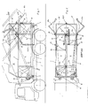
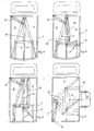
- FIG. 1 and 2 show a container 3 which is divided into compartments 8 and 9 by a vertical partition 6, and into compartment 10 by a horizontal partition 7, that is to say divided into three compartments.
- the rigid partition 6 is arranged in the middle of the container, with a pivotable flap 11 and 12 connecting at the front and rear.
- the rear flap forms the oscillating piston 12 which can be pivoted through 180 ° by means of two hydraulic cylinders 13, 14.
- the oscillating piston 12 represents the compression device, the swivel space simultaneously forming the waste collection volume.
- a pivotable flap 11 is also provided, which serves for the variable container division of the two compartments 8 and 9.
- pivot wall 11 can be brought into position 11a or 11b; but it also sets itself automatically when it is brought into the floating position in accordance with the different amounts of waste in the chambers 8, 9.
- horizontal partition 7 forms a compartment 10 at the top, which can be opened or closed by pivoting by means of hydraulic cylinder 32 of a prismatic tailgate 20.
- either the two compartments 9 or the compartment 10 can be filled. If compartments 8 or 9 are filled, flap 20 is first brought into position 20a. After filling the swivel space of the swivel piston 12, the flap 20 is pressed down again, so that the garbage can no longer escape upwards during the movement of the oscillating piston and is forced into one of the chambers 8 or 9.
- the oscillating piston 12, which is pivotable about the axis 16, is in the position 12 or 12a, depending on the compartment 8 or 9 to be filled, so that a pivoting angle of 180 ° is produced.
- the container 3 can be pivoted about the front and rear bearing point 4 by means of laterally arranged hydraulic cylinders 23, 24.
- the container 3 is pivoted about the front pivot point 4.
- the container is pivoted about the rear bearing point 5.
- the bearing points 4 and 5 are components of an auxiliary frame 2 which is firmly connected to the chassis frame 1.
- the two lower compartments 8 and 9 are emptied by means of extension pistons 18 and 19, respectively, which reach positions 18a and 19a during extension and the compartments 8 and 9 can be emptied separately, depending on the position of the oscillating piston 12.
- the rear cover which, as shown in FIG. 3, consists of two parts 26, 27 which can be pivoted about the bearings 28, 29, must be opened.
- the two cover halves 26, 27 are pivoted into positions 26a and 27a.
- the rear lid 26, 27 is closed centrally by means of two hydraulic cylinders 30, 31.
- the flap 20 is pivoted horizontally downward with the rear lid 26, 27 open and the container 3 is pivoted up about the rear bearing point 5.
- the flap 20 assumes the position 20b.
- the oscillating piston 12 describes the same radius “R” as the swiveling flap 11 used for dividing the containers.
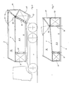
- FIG. 3 shows a vehicle, similar to that in Fig. 1, however, the vertical partition 33 is completely designed as a swivel wall.
- the rigid portion of the partition is reduced to zero, so that the two flaps of the oscillating piston 12 and the partition 33 can be moved about the same pivot point 16.
- the pivoting of the partition wall 33 is then expediently carried out in the front region, due to its length, by means of the hydraulic cylinders 34, 35 and a pair of levers 36 rotatable about the bearing point 37.
- this is on the top of the container at the bearings 38, 39 designed to be pivotable, so that no space is required on the side, but probably above the vehicle.
- the variable division is a maximum in the embodiment according to FIG. 4.
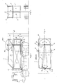
- Fig. 6 shows an embodiment in which the axis 16 of the oscillating piston 12 is probably in the plane of the vertical partition 6, but is inclined to a plane perpendicular to the direction of travel. The pouring edge of the rear cover 40 will be lower.
- Fig. 7 shows a container 3 with three chambers 8, 9, 10, in which the horizontal partition 7 is arranged inclined, so that the two pivotable parts of the partition 11 and 12 have different heights and the filling of the upper chamber 10 facilitated by this inclined position becomes. 1 to 7 require a rear loading device with which two different lifting heights can be reached, depending on the filling of the chambers 8 or 9 or the upper chamber 10.
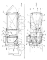
- FIGS. 8 and 9 show a two-chamber arrangement in which the Container 3 is mounted upside down on the chassis 1c, so that the loading device 50 and the oscillating piston 12 are arranged in the front, directly behind the driver's cab.
- the advantage is that the vehicle can only be operated by one person due to the side loading and the short distances traveled by the vehicle operator.
- the swivel wall responsible for the variable division of the compartments 8, 9 48 is mounted on the rear side in this embodiment and can be pivoted by means of hydraulic cylinder 46.
- the oscillating piston 12 in FIGS. 8 and 9 again forms the collecting space of the loosely poured garbage from the garbage container 51 in the size of its swiveling range.
- the compression in the individual chambers 8, 9 is now carried out by pivoting the oscillating piston 12, which has the same height as the fixed partition 6, wherein compression can also be achieved transversely to the direction of travel by moving the pivot wall 48.
- the extension pistons 18, 19 arranged on the front which can be moved by means of telescopic cylinders 21, 22, have on their side inclined towards the container 3 the radius which the oscillating piston 12 serving for compression describes.
- a hydraulic flap 43 is provided on the upper side of the filling space and is closed before each stroke of the oscillating piston.
- a side tipper 50 known per se which is mounted between the driver's cab and the waste container 3, can be used to fill the waste vehicle.
- the rear lid 41 is opened after unlocking the locking device 52 mounted in the container 3 and the garbage is emptied to the rear with the help of the extension pistons 18, 19, with the oscillating piston 12 and the adjustment flap 48 in the middle of the container have to be pivoted.
- the closure flap 43 which is actuated with the aid of the two external hydraulic cylinders 44a, 44b, is in turn closed after each filling by the container 51 and the oscillating piston 12 is set in motion.
- the rear cover 41 is designed in the form of a circular arc on its inside and seals against the pivot wall 48. In the rear area, waste is compacted by and moving the pivot wall 48 by means of the hydraulic or pneumatic cylinder 46.
- 12 to 15 show different variants of a two-chamber vehicle according to the invention, where the rigid portion of the partition wall has been reduced to zero and the pivot wall 53 itself, as shown in FIGS. 13, 14 and 15, carries the oscillating piston 12. 15, the swivel wall is arranged transversely to the direction of travel. The loading is then carried out by a lateral loading device 56, approximately in the middle of the container on the long side.
- 16 and 17 show an embodiment of the oscillating piston 12 and also of the movable partition 11, 33, 48, on the circumference of which cutting devices 57, 58 are provided, which can be adjusted radially or axially by means of fastening screws 59 in the elongated holes 60.
- FIGS. 8 and 9 a kind of shark teeth 49 are provided on the walls of the container 3 in order to prevent the garbage from receding into the collecting trough. In the embodiment according to FIG. 10, this is also achieved by the front step in the container 3, since the waste can flow with difficulty from a larger cross-section into a smaller cross-section.
- 3 shark teeth 49 could also be provided on the sloping shoulder of the container.
- the rigid partition 6 or the bearing points 16 and 17 the movable pivoting wall 48, 11, 33 and the oscillating piston 12 are normally seen in the direction of travel, arranged in the middle of the container, but could also be provided eccentrically, especially on designs as shown in FIGS. 12 to 15, where the oscillating piston 12 on the movable partition 53 is rotatably mounted.
- the oscillating piston 12 can be triangular, trapezoidal or semicircular, for example.
Landscapes
- Engineering & Computer Science (AREA)
- Mechanical Engineering (AREA)
- Refuse-Collection Vehicles (AREA)
Applications Claiming Priority (2)
| Application Number | Priority Date | Filing Date | Title |
|---|---|---|---|
| AT2525/88 | 1988-10-12 | ||
| AT2525/88A AT392622B (de) | 1988-10-12 | 1988-10-12 | Mehrkammer-muellsammelfahrzeug |
Publications (1)
| Publication Number | Publication Date |
|---|---|
| EP0365514A1 true EP0365514A1 (fr) | 1990-04-25 |
Family
ID=3535833
Family Applications (1)
| Application Number | Title | Priority Date | Filing Date |
|---|---|---|---|
| EP89890260A Ceased EP0365514A1 (fr) | 1988-10-12 | 1989-10-05 | Véhicule de ramassage d'ordures à plusieurs compartiments |
Country Status (2)
| Country | Link |
|---|---|
| EP (1) | EP0365514A1 (fr) |
| AT (1) | AT392622B (fr) |
Cited By (11)
| Publication number | Priority date | Publication date | Assignee | Title |
|---|---|---|---|---|
| EP0506057A1 (fr) * | 1991-03-27 | 1992-09-30 | Marathon Equipment Company | Dispositif pour entreposer et comprimer des ordures ménagères |
| DE9216943U1 (de) * | 1992-12-12 | 1993-02-18 | Gerhard Husmann Maschinenfabrik und Containerbau GmbH & Co. KG, 2992 Dörpen | Vorrichtung zum Sammeln und Verdichten von Abfällen |
| DE4226978A1 (de) * | 1992-08-14 | 1994-02-17 | Horst Dipl Ing Koester | Containerpresse |
| WO1994005570A1 (fr) * | 1992-09-04 | 1994-03-17 | The Heil Company | Appareil destine a compacter des materiaux recyclables separes |
| EP0625118A4 (en) * | 1992-02-10 | 1994-12-28 | Firebelt Pty. Limited | A side-loading refuse vehicle. |
| AU697334B2 (en) * | 1993-09-28 | 1998-10-01 | Macdonald Johnston Engineering Company Pty Limited | Expansion panel |
| US6071057A (en) * | 1997-05-02 | 2000-06-06 | Duron; Philippe | Container body for recyclable refuse collection vehicle |
| DE4121442C2 (de) * | 1990-06-29 | 2001-03-15 | Vc Recycling Patentverwertung | Müllsammel- und Transportsystem |
| US6302636B1 (en) * | 1997-05-02 | 2001-10-16 | Markland Inc. | Container body for recyclable refuse collection vehicle |
| NL1038055C2 (nl) * | 2010-06-18 | 2011-12-20 | Rimetaal Holding B V | Inrichting voor het verdichten van materiaal, in het bijzonder kunststofafval. |
| CN110980056A (zh) * | 2019-11-26 | 2020-04-10 | 福建龙马环卫装备股份有限公司 | 垃圾分类收集车及垃圾分类收集方法 |
Citations (3)
| Publication number | Priority date | Publication date | Assignee | Title |
|---|---|---|---|---|
| DE2914532A1 (de) * | 1978-04-17 | 1979-10-25 | Mut Masch & Transport | Fahrzeug zum transport von massenguetern, insbesondere muell |
| DE3537546A1 (de) * | 1985-10-22 | 1987-04-23 | Wolfgang Knierim Vertriebs Gmb | Mehrkammer-abfallsammelfahrzeug |
| DE8706418U1 (de) * | 1987-05-05 | 1987-06-25 | Faun Umwelttechnik GmbH, 27711 Osterholz-Scharmbeck | Müllfahrzeug |
-
1988
- 1988-10-12 AT AT2525/88A patent/AT392622B/de not_active IP Right Cessation
-
1989
- 1989-10-05 EP EP89890260A patent/EP0365514A1/fr not_active Ceased
Patent Citations (3)
| Publication number | Priority date | Publication date | Assignee | Title |
|---|---|---|---|---|
| DE2914532A1 (de) * | 1978-04-17 | 1979-10-25 | Mut Masch & Transport | Fahrzeug zum transport von massenguetern, insbesondere muell |
| DE3537546A1 (de) * | 1985-10-22 | 1987-04-23 | Wolfgang Knierim Vertriebs Gmb | Mehrkammer-abfallsammelfahrzeug |
| DE8706418U1 (de) * | 1987-05-05 | 1987-06-25 | Faun Umwelttechnik GmbH, 27711 Osterholz-Scharmbeck | Müllfahrzeug |
Cited By (13)
| Publication number | Priority date | Publication date | Assignee | Title |
|---|---|---|---|---|
| DE4121442C2 (de) * | 1990-06-29 | 2001-03-15 | Vc Recycling Patentverwertung | Müllsammel- und Transportsystem |
| US5415086A (en) * | 1991-03-27 | 1995-05-16 | Marathon Equipment Company | Apparatus for storing and compacting recyclable and nonrecyclable waste materials in separate storage compartments, the capacity of which can be readily varied |
| EP0506057A1 (fr) * | 1991-03-27 | 1992-09-30 | Marathon Equipment Company | Dispositif pour entreposer et comprimer des ordures ménagères |
| EP0625118A4 (en) * | 1992-02-10 | 1994-12-28 | Firebelt Pty. Limited | A side-loading refuse vehicle. |
| DE4226978A1 (de) * | 1992-08-14 | 1994-02-17 | Horst Dipl Ing Koester | Containerpresse |
| WO1994005570A1 (fr) * | 1992-09-04 | 1994-03-17 | The Heil Company | Appareil destine a compacter des materiaux recyclables separes |
| DE9216943U1 (de) * | 1992-12-12 | 1993-02-18 | Gerhard Husmann Maschinenfabrik und Containerbau GmbH & Co. KG, 2992 Dörpen | Vorrichtung zum Sammeln und Verdichten von Abfällen |
| AU697334B2 (en) * | 1993-09-28 | 1998-10-01 | Macdonald Johnston Engineering Company Pty Limited | Expansion panel |
| US6071057A (en) * | 1997-05-02 | 2000-06-06 | Duron; Philippe | Container body for recyclable refuse collection vehicle |
| US6302636B1 (en) * | 1997-05-02 | 2001-10-16 | Markland Inc. | Container body for recyclable refuse collection vehicle |
| NL1038055C2 (nl) * | 2010-06-18 | 2011-12-20 | Rimetaal Holding B V | Inrichting voor het verdichten van materiaal, in het bijzonder kunststofafval. |
| CN110980056A (zh) * | 2019-11-26 | 2020-04-10 | 福建龙马环卫装备股份有限公司 | 垃圾分类收集车及垃圾分类收集方法 |
| CN110980056B (zh) * | 2019-11-26 | 2022-08-09 | 福龙马集团股份有限公司 | 垃圾分类收集车及垃圾分类收集方法 |
Also Published As
| Publication number | Publication date |
|---|---|
| AT392622B (de) | 1991-05-10 |
| ATA252588A (de) | 1990-10-15 |
Similar Documents
| Publication | Publication Date | Title |
|---|---|---|
| EP0235784B1 (fr) | Dispositif de culbutage pour un véhicule à ordures | |
| EP0364835B1 (fr) | Véhicule de ramassage d'ordures | |
| EP0405345B1 (fr) | Véhicule de ramassage d'ordures | |
| DE4020221A1 (de) | Fahrzeug zum einsammeln von abfaellen | |
| EP0336003A2 (fr) | Véhicule à ordures | |
| AT392622B (de) | Mehrkammer-muellsammelfahrzeug | |
| DE19518434C2 (de) | Müllsammel- und Transportsystem | |
| DE69213286T2 (de) | Vorrichtung zum Lagern und Verdichten von Müll | |
| DE3244216A1 (de) | Vorrichtung zum verdichten und entleeren von muell | |
| DE3873582T2 (de) | Muellfahrzeug. | |
| EP0574374A1 (fr) | Récipient collecteur d'ordures avec compartiment à volume variable | |
| EP3486197A1 (fr) | Dispositif couvercle pour un récipient de collecte de déchets | |
| DE2254641A1 (de) | Muellverladevorrichtung | |
| DE3434581C1 (de) | Müllsammelfahrzeug | |
| DE920298C (de) | Wagenaufbau fuer Lastkraftwagen, insbesondere fuer Muellwagen | |
| EP0060966A1 (fr) | Dispositif pour l'amassage et le transport des ordures | |
| DE9311235U1 (de) | Mehrkammeraufbau mit Leichtmüllverdichter für Kleintransporter | |
| DD296658A5 (de) | Muellsammelfahrzeug | |
| AT394839B (de) | Mehrkammer-muellsammelfahrzeug | |
| DE3828352A1 (de) | Umladeeinrichtung fuer schuettbare gueter mit transportablem behaelter | |
| DE2300636B2 (de) | Müllbehälter mit PreBplatte | |
| DE3821843C2 (fr) | ||
| DE8427750U1 (de) | Müllsammelfahrzeug | |
| DE69401753T2 (de) | Abdichtungsvorrichtung für auswechselbare behälter | |
| DE4237407C1 (de) | Müllsammelfahrzeug |
Legal Events
| Date | Code | Title | Description |
|---|---|---|---|
| PUAI | Public reference made under article 153(3) epc to a published international application that has entered the european phase |
Free format text: ORIGINAL CODE: 0009012 |
|
| AK | Designated contracting states |
Kind code of ref document: A1 Designated state(s): BE CH DE ES FR GB GR IT LI LU NL SE |
|
| 17P | Request for examination filed |
Effective date: 19900817 |
|
| 17Q | First examination report despatched |
Effective date: 19911211 |
|
| RAP1 | Party data changed (applicant data changed or rights of an application transferred) |
Owner name: BROSOWITSCH, JOSEF |
|
| STAA | Information on the status of an ep patent application or granted ep patent |
Free format text: STATUS: THE APPLICATION HAS BEEN REFUSED |
|
| 18R | Application refused |
Effective date: 19940217 |