EP0365557B1 - Agencement de positionnement et son utilisation - Google Patents
Agencement de positionnement et son utilisation Download PDFInfo
- Publication number
- EP0365557B1 EP0365557B1 EP88905376A EP88905376A EP0365557B1 EP 0365557 B1 EP0365557 B1 EP 0365557B1 EP 88905376 A EP88905376 A EP 88905376A EP 88905376 A EP88905376 A EP 88905376A EP 0365557 B1 EP0365557 B1 EP 0365557B1
- Authority
- EP
- European Patent Office
- Prior art keywords
- positioning
- component
- components
- positioning device
- positioning member
- Prior art date
- Legal status (The legal status is an assumption and is not a legal conclusion. Google has not performed a legal analysis and makes no representation as to the accuracy of the status listed.)
- Expired - Lifetime
Links
Images

Classifications
-
- B—PERFORMING OPERATIONS; TRANSPORTING
- B23—MACHINE TOOLS; METAL-WORKING NOT OTHERWISE PROVIDED FOR
- B23Q—DETAILS, COMPONENTS, OR ACCESSORIES FOR MACHINE TOOLS, e.g. ARRANGEMENTS FOR COPYING OR CONTROLLING; MACHINE TOOLS IN GENERAL CHARACTERISED BY THE CONSTRUCTION OF PARTICULAR DETAILS OR COMPONENTS; COMBINATIONS OR ASSOCIATIONS OF METAL-WORKING MACHINES, NOT DIRECTED TO A PARTICULAR RESULT
- B23Q16/00—Equipment for precise positioning of tool or work into particular locations not otherwise provided for
- B23Q16/02—Indexing equipment
- B23Q16/021—Indexing equipment in which only the positioning elements are of importance
-
- B—PERFORMING OPERATIONS; TRANSPORTING
- B23—MACHINE TOOLS; METAL-WORKING NOT OTHERWISE PROVIDED FOR
- B23Q—DETAILS, COMPONENTS, OR ACCESSORIES FOR MACHINE TOOLS, e.g. ARRANGEMENTS FOR COPYING OR CONTROLLING; MACHINE TOOLS IN GENERAL CHARACTERISED BY THE CONSTRUCTION OF PARTICULAR DETAILS OR COMPONENTS; COMBINATIONS OR ASSOCIATIONS OF METAL-WORKING MACHINES, NOT DIRECTED TO A PARTICULAR RESULT
- B23Q16/00—Equipment for precise positioning of tool or work into particular locations not otherwise provided for
- B23Q16/02—Indexing equipment
- B23Q16/08—Indexing equipment having means for clamping the relatively movable parts together in the indexed position
-
- B—PERFORMING OPERATIONS; TRANSPORTING
- B29—WORKING OF PLASTICS; WORKING OF SUBSTANCES IN A PLASTIC STATE IN GENERAL
- B29C—SHAPING OR JOINING OF PLASTICS; SHAPING OF MATERIAL IN A PLASTIC STATE, NOT OTHERWISE PROVIDED FOR; AFTER-TREATMENT OF THE SHAPED PRODUCTS, e.g. REPAIRING
- B29C45/00—Injection moulding, i.e. forcing the required volume of moulding material through a nozzle into a closed mould; Apparatus therefor
- B29C45/17—Component parts, details or accessories; Auxiliary operations
- B29C45/26—Moulds
- B29C45/2602—Mould construction elements
- B29C45/2606—Guiding or centering means
Definitions
- the invention relates to a positioning device for joining two components in a predetermined relative position with the features mentioned in the preamble of claim 1.
- a positioning device for joining two components in a predetermined relative position with the features mentioned in the preamble of claim 1.
- Such a device is known from EP-A-111 092.
- There is a tapered positioning element which, when joined, penetrates into a positioning recess recessed from a membrane.
- the membrane is supported on a collar at a distance from the positioning recess and fastened to the second component by means of screws.
- the object of the invention is to provide a positioning device of the same type, in which the joining accuracy is maintained even when the joining process is repeated, despite the stresses that arise in the plate-like carrier during joining.
- FIGS. 1 and 2 show the basic operating principles of the positioning device according to the invention.
- the two components 1oo and 1o2 are to be centered with respect to an axis 104 which runs through the center of the ball 1o6.
- Each component 100, 102 is provided with a positioning plate 108 or 110 of different construction, each of which is inserted into a corresponding hole in the component concerned.
- the plate 108 is actually only a perforated disc, supported near its outer circumference by a shoulder of the component 100, while the plate 110 is cup-shaped with a central perforation in the base and is supported with the free edge of its edge.
- the ball 106 is pierced and a clearance screw 112 penetrates it with play, which can be screwed into the component 102 and presses with its head onto the opposite outer surface of the component 100.
- the ball diameter which can be defined by contact zones of the positioning recesses in the positioning plates when the joining surfaces 116, 118 abut when the ball is removed, has an undersize with respect to the ball 1o6, so that, as shown in FIG mutually opposite joining surfaces is present.
- the parts 106, 108 and 110 are elastically deformed, namely the ball 106 by compressive stresses and the plates 108 and 110 by compressive and - mainly - bending stresses, the division of the deformation components by the designer by appropriate choice of Dimensions can be made.
- the modulus of elasticity of the materials used also plays a role, as does the coefficient of friction acting between them and the profile of the positioning recesses and the selected contact area of the ball 106 (closer to its equator or closer to its poles). It has been shown that even with ball diameters of 60 mm, a repeat accuracy of the centering in the order of magnitude of 1 micron and smaller can be achieved without a disproportionately high clamping force having to be applied.
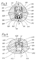
- FIGS. 3 and 4 show positioning devices which can be used in a very general way, for example in the field of mechanical engineering or device construction.
- the positioning devices have been realized through the interaction of standardized components.
- the ones carrying the positioning recesses 328, 418 and on their membrane-shaped parts in the axial direction deformable components are designed as press-in "positioning inserts".
- These standardized positioning inserts are provided with hardened and ground surfaces on the outside diameter and on the positioning recess and have a press-in phase on the outside cylinder.
- FIGS. 3 and 4 correspond to those in FIG. 2, ie the two components 300 and 302 to be positioned in a precise relative position are clamped together by a clamping force F on their joining surfaces 324 and 326 after a joining gap (similar to 114 in FIG 1) has been eliminated while deforming the plate-shaped part of the positioning inserts 304 or 404 (in FIG. 4).
- the depth of the positioning inserts 304 pressed into the bores 312 can be predetermined or changed by screw inserts 308.
- a hexagon socket 31o enables the generation of a screwing movement.
- the interference fit of the positioning insert 304 ensures a concentric fit of the positioning recess 328 relative to the component bore 312 due to the lack of play and at the same time ensures good transverse axial rigidity of the positioning insert.
- a threaded bolt 314 is welded on, which is in engagement with a nut 316 which is supported against disc springs 318. Falling out of the plate springs and nut is prevented by 2 locking rings 320, 322.
- the positioning insert 404 is seated with the plate-shaped component 420 having the positioning recess 418 on the bottom 408 of the component bore 410.
- the positioning element 406 has a spherical, but preferably spherical, shaped contact zone 416 protruding beyond the joining surface 324 and a cylindrical part 414 with which it is pressed into the receiving bore 412 of the component 302.
- a nozzle 426 is inserted, the inner bore of which is connected to a compressed air source, not shown.
- test air can be let in through the nozzle 426 in the now closed interior of bore 41o, in order to be able to conclude that the positioning process has been carried out correctly by means of the tightness to be tested.
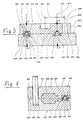
- FIGS. 5 and 6 Special fields of application of the positioning devices described so far are shown in FIGS. 5 and 6.
- FIG. 5 shows an advantageous application of the positioning device according to the invention in connection with the positioning of workpieces on clamping bases.
- a component 502 to be machined is positioned relative to the clamping base 504 by means of two positioning devices 544, 546 and clamped with its clamping surface 548 under the action of clamping forces symbolized by arrows F against the mounting surface 550 of the clamping base.
- the central axes of the positioning devices brought into coincidence by means of the spherical positioning elements 528, 530 are identified by the lines 512, 526.
- Positioning inserts 524, 538 (similar to part 404 in FIG. 4), which form the actual positioning recesses 540, 542 with their central bores, are inserted on the left in the upper and in the lower part in the receiving bores 522, 536.
- R e CHTS is formed the positioning in the lower part of the locating insert 534 and molded directly into the component 502 in the upper part.
- the clamped component 502 could be any workpiece.
- the component 502 is one which belongs to the species of the standard parts, which are pre-processed to a certain extent by the standard parts manufacturer and which subsequently be reworked by the user to produce the final shape.
- Subsequent processing e.g.
- the production of a cylindrical recess 520 centered on the center axis 516 usually takes place by means of several successive work operations (e.g. milling, eroding, grinding) on different work machines.
- each operation requires a precise reference to the machining features created in the previous operation. It may also be necessary for the processing features to be created by the user into one exact reference to the dimensions already created by the manufacturer, e.g. hole 508.
- the positioning recesses 540, 518 already made by the manufacturer have the task in the course of further processing for the user to carry out an exact alignment of the component with each new work operation and to serve as a reference material measure for the dimensions to be produced during the operation.
- the clamping pad 504 can be different for each work operation and can always remain on the same processing machine.
- the measuring system of the processing machine is advantageously always brought into a precise dimensional reference to the clamping base, for which purpose e.g. the center axis of the positioning inserts 538, 534 can be used.
- the machine measuring system is thus automatically aligned precisely relative to component 502.
- the positioning recess 518 can be made directly in the component body.
- a spherical cap-shaped design of the contact zones is advantageous. Another possibility for saving costs is that the standard component 502 initially only has receiving bores 522 into which the positioning inserts 524 with the actual positioning recesses 540 are subsequently inserted (pressed in), the positioning inserts 524 being reusable several times.
- the clamping pad 504 will usually have a plurality of positioning recesses in order to accommodate components of different sizes.
- the center axes of the positioning recesses of the component and the mounting base preferably lie on the intersection of grid lines of a standard grid.
- FIG. 6 shows the use of a positioning device on an injection molding tool for extremely precise centering of the two mold halves 602 and 604.
- the positioning device 628 and the guide column 608 are only shown once in the drawing, although both are each present twice.
- the guide columns 608 are inserted with undersize in the guide bores 612. They take over the guiding of the upper mold half when opening the tool to eject the molded part 606 and also when closing the tool as a pre-centering for the positioning process which begins only in the last phase of the closing path by the positioning devices 628.
- the positioning devices 628 have positioning inserts 616 , 620, of which only part 616 has an axially deformable plate-shaped component.
- the forces symbolized by the arrows F can not only be generated manually by mechanically acting clamping elements, but can also be introduced magnetically, electromagnetically, hydraulically or by other means by means of negative pressure.
Landscapes
- Engineering & Computer Science (AREA)
- Mechanical Engineering (AREA)
- Manufacturing & Machinery (AREA)
- Jigs For Machine Tools (AREA)
- Machine Tool Positioning Apparatuses (AREA)
- Multi-Conductor Connections (AREA)
- Connection Of Plates (AREA)
Abstract
Claims (7)
- Dispositif de positionnement pour assembler deux pièces de construction dans une position relative prédéterminée, dans lequel:(a) une première pièce de construction (102, 302) comprend un élément de positionnement (106, 416) ayant une symétrie de révolution vis-à-vis d'un axe (104, 428) en se rétrécissant par une courbe sphérique convexe près de zones de contact (430),(b) une deuxième pièce de construction (100, 300) comprend une cavité de positionnement (418) ayant une symétrie de révolution vis-à-vis d'un axe (104, 428) en se rétrécissant vers l'intérieur près de zones de contact (432), cette deuxième pièce pouvant être assemblée à la première pièce de telle façon que les deux axes coincident,(c) les deux pièces de construction présentent des surfaces de jonction opposées (116, 118, 326, 324) qui après assemblage s'appliquent l'une sur l'autre, l'élément de positionnement ainsi que la cavité de positionnement ayant des dimensions telles que le processus d'assemblage se déroule comme spécifié dans les caractéristiques (d) et (e) ci-dessous,(d) pendant une première phase d'assemblage, l'élément de positionnement pénètre dans la cavité de positionnement, jusqu'à ce que les zones de contact prévues pour le centrage des deux pièces viennent en contact l'une de l'autre, alors que subsiste encore un intervalle d'assemblage entre les surfaces d'assemblage,(e) pendant une seconde phase d'assemblage, l'intervalle d'assemblage est supprimé sous l'action d'une force de serrage axial, le matériau étant soumis, près des zones de contact, à une déformation élastique qui est essentiellement une déformation de flexion avec déplacement du matériau essentiellement dans la direction axiale,(f) l'élément de positionnement et/ou la cavité de positionnement sont prévus sur un support en forme de plateau (108, 420) qui ne prend appui axialement que près de sa périphérie extérieure et qui peut se déformer élastiquement dans la direction axiale dans sa zone centrale, caractérisé en ce que le support en forme de plateau (108, 420) constitue le fond d'une cuvette (110, 404) insérée dans une cavité d'une pièce de construction.
- Dispositif de positionnement suivant la revendication 1, caractérisé en ce que les deux pièces de construction présentent des cavités de positionnement (418, 412) entre lesquelles est placé l'élément de positionnement (106, 416).
- Dispositif de positionnement suivant la revendication 1, caractérisé en ce que le support en forme de plateau (108, 420) est inséré dans la pièce de construction correspondante par ajustement avec serrage dans une direction radiale.
- Dispositif de positionnement suivant l'une quelconque des revendications 1 à 3, caractérisé en ce que l'élément de positionnement (416) présente une forme sphérique au moins d'un côté et au moins dans la zone de contact avec la cavité de positionnement (418).
- Dispositif de positionnement suivant la revendication 4, caractérisé en ce que l'élément de positionnement (306) est une bille.
- Dispositif de positionnement suivant l'une quelconque des revendications 3 à 5, caractérisé en ce que l'élément de positionnement (306) comprend une saillie de maintien (314) s'étendant dans l'une des pièces de construction et permettant une fixation autonome de cet élément de positionnement.
- Dispositif de positionnement suivant l'une quelconque des revendications 1 à 6, caractérisé en ce qu'il est prévu en double ou en multiple (544, 546) pour le positionnement de deux pièces de construction (502, 504).
Priority Applications (1)
| Application Number | Priority Date | Filing Date | Title |
|---|---|---|---|
| AT88905376T ATE89210T1 (de) | 1987-06-23 | 1988-06-21 | Positioniereinrichtung und deren verwendung. |
Applications Claiming Priority (6)
| Application Number | Priority Date | Filing Date | Title |
|---|---|---|---|
| DE3720604 | 1987-06-23 | ||
| DE3720604 | 1987-06-23 | ||
| DE3722309 | 1987-07-07 | ||
| DE3722308 | 1987-07-07 | ||
| DE3722308 | 1987-07-07 | ||
| DE3722309 | 1987-07-07 |
Publications (2)
| Publication Number | Publication Date |
|---|---|
| EP0365557A1 EP0365557A1 (fr) | 1990-05-02 |
| EP0365557B1 true EP0365557B1 (fr) | 1993-05-12 |
Family
ID=27196129
Family Applications (1)
| Application Number | Title | Priority Date | Filing Date |
|---|---|---|---|
| EP88905376A Expired - Lifetime EP0365557B1 (fr) | 1987-06-23 | 1988-06-21 | Agencement de positionnement et son utilisation |
Country Status (6)
| Country | Link |
|---|---|
| US (1) | US5397231A (fr) |
| EP (1) | EP0365557B1 (fr) |
| JP (1) | JPH02503887A (fr) |
| KR (1) | KR970005613B1 (fr) |
| DE (1) | DE3881050D1 (fr) |
| WO (1) | WO1988010172A1 (fr) |
Families Citing this family (17)
| Publication number | Priority date | Publication date | Assignee | Title |
|---|---|---|---|---|
| DE3831736C2 (de) * | 1988-09-17 | 1998-11-26 | Gedib Ingbuero Innovation | Positioniereinrichtung zweier Bauteile in vorgegebener Relativlage und deren Verwendung |
| DE4203853C2 (de) * | 1992-02-11 | 1993-11-25 | Guenter Meywald | Positioniervorrichtung für zwei zu fügende Bauteile |
| DE4428310A1 (de) * | 1994-08-10 | 1996-02-15 | Manfred Schanz | Befestigungsvorrichtung für ein Werkzeug oder Werkstück |
| DE59705344D1 (de) * | 1996-06-17 | 2001-12-20 | Certa Ag Reinach | Aufspannvorrichtung sowie Einrichtung zum positionsdefinierten Aufspannen eines Werkzeugs oder Werkstücks |
| US6101911A (en) * | 1996-09-04 | 2000-08-15 | Joseph B. Willey | Apparatus and method for automatically compensating for lateral runout |
| US6050160A (en) * | 1996-09-04 | 2000-04-18 | Joseph B. Willey | Apparatus and method for automatically compensating for lateral runout |
| EP0922529B1 (fr) * | 1997-12-11 | 2002-11-06 | Parotec AG | Unité pour connecter temporairement des parties d'un dispositif de palletisation et un dispositif de palettisation |
| US6367765B1 (en) * | 1999-09-09 | 2002-04-09 | Klaus A. Wieder | Mold vent |
| US6558145B2 (en) * | 2000-07-06 | 2003-05-06 | Klaus A. Wieder | Mold interlock |
| EP1211021B1 (fr) * | 2000-11-02 | 2006-07-19 | IEMCA Giuliani Macchine Italia S.p.A. | Machine-outil de transfert |
| EP1364746B1 (fr) * | 2002-05-21 | 2005-12-21 | Michel Yerly | Dispositif pour l'accouplement amovible de deux organes d'accouplement et équipement pour le préréglage d'outils de machine comprenant ce dispositif |
| US7536935B2 (en) * | 2005-04-07 | 2009-05-26 | Pro-Cut Licensing Company, Llc | Brake rotor resurfacing |
| KR100726227B1 (ko) * | 2006-07-03 | 2007-06-08 | 현대자동차주식회사 | 부품 가공용 기준면 설정장치 |
| CN101125726B (zh) * | 2006-08-16 | 2011-05-04 | 鸿富锦精密工业(深圳)有限公司 | 成型模具 |
| SE538609C2 (en) * | 2015-01-20 | 2016-10-04 | Sundström Erik | Device for detachable and repeatable positioning of two objects in relation to each other |
| CN106273291A (zh) * | 2015-05-20 | 2017-01-04 | 鸿富锦精密工业(深圳)有限公司 | 开闭器装置及具有该开闭器装置的模具 |
| SE544647C2 (en) * | 2020-10-21 | 2022-10-04 | Zerofix Tooling Ab | Positioning device for a positioning system |
Family Cites Families (15)
| Publication number | Priority date | Publication date | Assignee | Title |
|---|---|---|---|---|
| DE885951C (de) * | 1941-11-18 | 1953-08-10 | Ernst Hauer & Co | Mehrfachstahlhalter |
| US2908195A (en) * | 1958-01-20 | 1959-10-13 | Enco Mfg Co | Turret toolpost |
| CH515379A (de) * | 1969-01-27 | 1971-12-31 | Ciba Geigy Ag | Verwendung wässeriger Emulsionen zum dauerhaft Wasserabweisendmachen von Textilmaterialien |
| US3723927A (en) * | 1969-05-05 | 1973-03-27 | Gen Dynamics Corp | Magnetic holding means in a surface plate dimensional measuring apparatus |
| DE2537146C3 (de) * | 1975-08-21 | 1980-05-14 | Hubert Dipl.-Ing. 5820 Gevelsberg Bald | Baueinheit aus zwei in eine Relativlage zu positionierenden Bauteilen |
| CH624329A5 (en) * | 1977-11-08 | 1981-07-31 | Bald Hubert | Method of clamping a workpiece in order to machine or inspect it, and clamping body for carrying out the method |
| DE3035229A1 (de) * | 1980-09-18 | 1982-04-29 | Dieter Hansen GmbH, 6116 Eppertshausen | Anordnung aus werkzeughalter und spindel-spannfutter fuer werkzeugmaschinen und kopierverfahren zur herstellung |
| US4372738A (en) * | 1981-10-27 | 1983-02-08 | Pemco-Kalamazoo, Inc. | Collet lock for a mold assembly |
| US4512068A (en) * | 1982-08-23 | 1985-04-23 | Cincinnati Milacron Inc. | Pallet receiver with compliant pin and socket registration |
| EP0111092B2 (fr) * | 1982-10-18 | 1992-11-25 | Erowa AG | Dispositif d'accouplement |
| DE3436182C1 (de) * | 1984-10-03 | 1985-11-14 | Karl 7298 Loßburg Hehl | Spritzgiessform fuer Kunststoff-Spritzgiessmaschine mit Verriegelungseinrichtung |
| US4561626A (en) * | 1984-10-25 | 1985-12-31 | Pemco-Kalamazoo, Inc. | Mold opening device |
| US4855558A (en) * | 1986-07-29 | 1989-08-08 | System 3R International Ab | Clamping device for a tool at a machine tool, particularly at a die sinking electric discharge machine |
| DE3625608A1 (de) * | 1986-07-29 | 1988-04-21 | 3R Management Ab | Spannvorrichtung fuer ein werkzeug an einer werkzeugmaschine, insbesondere einer senkerodiermaschine |
| DE3933348A1 (de) * | 1989-10-06 | 1991-04-18 | Kloeckner Ferromatik Desma | Formschliessvorrichtung fuer eine spritzgiessmaschine |
-
1987
- 1987-06-23 US US08/101,264 patent/US5397231A/en not_active Expired - Fee Related
-
1988
- 1988-06-21 DE DE8888905376T patent/DE3881050D1/de not_active Expired - Fee Related
- 1988-06-21 KR KR1019890700327A patent/KR970005613B1/ko not_active Expired - Lifetime
- 1988-06-21 WO PCT/EP1988/000546 patent/WO1988010172A1/fr not_active Ceased
- 1988-06-21 EP EP88905376A patent/EP0365557B1/fr not_active Expired - Lifetime
- 1988-06-21 JP JP63505065A patent/JPH02503887A/ja active Pending
Also Published As
| Publication number | Publication date |
|---|---|
| JPH02503887A (ja) | 1990-11-15 |
| KR890701281A (ko) | 1989-12-19 |
| EP0365557A1 (fr) | 1990-05-02 |
| DE3881050D1 (de) | 1993-06-17 |
| KR970005613B1 (ko) | 1997-04-18 |
| WO1988010172A1 (fr) | 1988-12-29 |
| US5397231A (en) | 1995-03-14 |
Similar Documents
| Publication | Publication Date | Title |
|---|---|---|
| EP0365557B1 (fr) | Agencement de positionnement et son utilisation | |
| EP1268123B1 (fr) | Dispositif pour fixer de fa on amovible des pieces a usiner sur des dispositifs d'usinage | |
| EP0818270B1 (fr) | Dispositif de serrage et dispositif pour le blocage indexé d'une pièce de travail ou d'un outil | |
| EP0753368B1 (fr) | Dispositif de serrage pour la fixation relative précise de 2 pièces | |
| DE202013005616U1 (de) | Positioniereinrichtung für Werkstückhaltevorrichtung | |
| DE19858159C2 (de) | Kupplungsvorrichtung | |
| EP0450383A1 (fr) | Dispositif de serrage et de centrage | |
| EP1741511B1 (fr) | Dispositif de serrage pour un outil ou une pièce à travailler | |
| EP0310967B1 (fr) | Dispositif de serrage | |
| DE10135233B4 (de) | Ringmaschine | |
| DE3901254C2 (fr) | ||
| EP2101948B1 (fr) | Dispositif et procédé de positionnement d'un outil ou d'une pièce sur une machine-outil | |
| DE4203853A1 (de) | Positioniervorrichtung fuer zwei zu fuegende bauteile | |
| DE3708363A1 (de) | Spannfutter fuer werkzeugmaschinen | |
| DE4005938C2 (fr) | ||
| DE3302432A1 (de) | Maschinengrundkoerper, insbesondere einer werkzeugmaschine, mit einer schlittengeradfuehrung aus feinstbearbeiteten stahlbalken von prismatischem querschnitt sowie verfahren zum ausrichten und befestigen des - stahlbalkens auf dem maschinengrundkoerper | |
| DE19756215C2 (de) | Schnell-Paß-System für Bauteile von Werkzeugmaschinen | |
| DE3439040A1 (de) | Vorrichtung zur verbindung eines werkzeughalters mit einer werkzeughalteraufnahme | |
| DE19860013C2 (de) | Vorrichtung zum Aufspannen eines Dichtringes auf einer Werkzeugmaschine | |
| EP0900628B1 (fr) | Sytème de raccord rapide | |
| DE4416262C1 (de) | Vorrichtung zur Befestigung eines Blasdornes einer Hohlkörperblasmaschine | |
| DE3820870A1 (de) | Einrichtung zum zentrieren einer wechselpalette bezueglich einer spannvorrichtungsachse und dafuer bestimmte positioniereinrichtung | |
| DE19514512C2 (de) | Einrichtung zum positionsdefinierten Aufspannen eines Werkstückes | |
| DD283096A5 (de) | Spannsystem fuer wechselbare ansatzwerkzeuge | |
| DE19705687C2 (de) | Verfahren zur hochgenauen Herstellung von Werkstückplatten, insbesondere zur hochgenauen Bearbeitung von Vorder- und Rückseite von Werkstückplatten |
Legal Events
| Date | Code | Title | Description |
|---|---|---|---|
| PUAI | Public reference made under article 153(3) epc to a published international application that has entered the european phase |
Free format text: ORIGINAL CODE: 0009012 |
|
| 17P | Request for examination filed |
Effective date: 19891123 |
|
| AK | Designated contracting states |
Kind code of ref document: A1 Designated state(s): AT BE CH DE FR GB IT LI NL SE |
|
| 17Q | First examination report despatched |
Effective date: 19910722 |
|
| GRAA | (expected) grant |
Free format text: ORIGINAL CODE: 0009210 |
|
| AK | Designated contracting states |
Kind code of ref document: B1 Designated state(s): AT BE CH DE FR GB IT LI NL SE |
|
| REF | Corresponds to: |
Ref document number: 89210 Country of ref document: AT Date of ref document: 19930515 Kind code of ref document: T |
|
| ITF | It: translation for a ep patent filed | ||
| REF | Corresponds to: |
Ref document number: 3881050 Country of ref document: DE Date of ref document: 19930617 |
|
| GBT | Gb: translation of ep patent filed (gb section 77(6)(a)/1977) |
Effective date: 19930526 |
|
| ET | Fr: translation filed | ||
| EAL | Se: european patent in force in sweden |
Ref document number: 88905376.5 |
|
| PGFP | Annual fee paid to national office [announced via postgrant information from national office to epo] |
Ref country code: GB Payment date: 19960516 Year of fee payment: 9 |
|
| PGFP | Annual fee paid to national office [announced via postgrant information from national office to epo] |
Ref country code: FR Payment date: 19960521 Year of fee payment: 9 |
|
| PGFP | Annual fee paid to national office [announced via postgrant information from national office to epo] |
Ref country code: SE Payment date: 19960523 Year of fee payment: 9 Ref country code: AT Payment date: 19960523 Year of fee payment: 9 |
|
| PGFP | Annual fee paid to national office [announced via postgrant information from national office to epo] |
Ref country code: CH Payment date: 19960524 Year of fee payment: 9 Ref country code: BE Payment date: 19960524 Year of fee payment: 9 |
|
| PGFP | Annual fee paid to national office [announced via postgrant information from national office to epo] |
Ref country code: NL Payment date: 19960630 Year of fee payment: 9 |
|
| PG25 | Lapsed in a contracting state [announced via postgrant information from national office to epo] |
Ref country code: GB Free format text: LAPSE BECAUSE OF NON-PAYMENT OF DUE FEES Effective date: 19970621 Ref country code: AT Effective date: 19970621 |
|
| PG25 | Lapsed in a contracting state [announced via postgrant information from national office to epo] |
Ref country code: SE Effective date: 19970622 |
|
| PG25 | Lapsed in a contracting state [announced via postgrant information from national office to epo] |
Ref country code: LI Free format text: LAPSE BECAUSE OF NON-PAYMENT OF DUE FEES Effective date: 19970630 Ref country code: CH Free format text: LAPSE BECAUSE OF NON-PAYMENT OF DUE FEES Effective date: 19970630 Ref country code: BE Effective date: 19970630 |
|
| BERE | Be: lapsed |
Owner name: GEDIB INGENIEURBURO UND INNOVATIONSBERATUNG G.M.B Effective date: 19970630 |
|
| PG25 | Lapsed in a contracting state [announced via postgrant information from national office to epo] |
Ref country code: NL Effective date: 19980101 |
|
| GBPC | Gb: european patent ceased through non-payment of renewal fee |
Effective date: 19970621 |
|
| REG | Reference to a national code |
Ref country code: CH Ref legal event code: PL |
|
| PG25 | Lapsed in a contracting state [announced via postgrant information from national office to epo] |
Ref country code: FR Free format text: LAPSE BECAUSE OF NON-PAYMENT OF DUE FEES Effective date: 19980227 |
|
| EUG | Se: european patent has lapsed |
Ref document number: 88905376.5 |
|
| NLV4 | Nl: lapsed or anulled due to non-payment of the annual fee |
Effective date: 19980101 |
|
| REG | Reference to a national code |
Ref country code: FR Ref legal event code: ST |
|
| REG | Reference to a national code |
Ref country code: FR Ref legal event code: ST |
|
| PGFP | Annual fee paid to national office [announced via postgrant information from national office to epo] |
Ref country code: DE Payment date: 20000823 Year of fee payment: 13 |
|
| PG25 | Lapsed in a contracting state [announced via postgrant information from national office to epo] |
Ref country code: DE Free format text: LAPSE BECAUSE OF NON-PAYMENT OF DUE FEES Effective date: 20020403 |
|
| PG25 | Lapsed in a contracting state [announced via postgrant information from national office to epo] |
Ref country code: IT Free format text: LAPSE BECAUSE OF NON-PAYMENT OF DUE FEES;WARNING: LAPSES OF ITALIAN PATENTS WITH EFFECTIVE DATE BEFORE 2007 MAY HAVE OCCURRED AT ANY TIME BEFORE 2007. THE CORRECT EFFECTIVE DATE MAY BE DIFFERENT FROM THE ONE RECORDED. Effective date: 20050621 |
|
| PLBE | No opposition filed within time limit |
Free format text: ORIGINAL CODE: 0009261 |
|
| STAA | Information on the status of an ep patent application or granted ep patent |
Free format text: STATUS: NO OPPOSITION FILED WITHIN TIME LIMIT |