EP0365574B1 - Dispositif de nettoyage d'huiles lubrifiantes dansdes boites de vitesses - Google Patents
Dispositif de nettoyage d'huiles lubrifiantes dansdes boites de vitesses Download PDFInfo
- Publication number
- EP0365574B1 EP0365574B1 EP19880905791 EP88905791A EP0365574B1 EP 0365574 B1 EP0365574 B1 EP 0365574B1 EP 19880905791 EP19880905791 EP 19880905791 EP 88905791 A EP88905791 A EP 88905791A EP 0365574 B1 EP0365574 B1 EP 0365574B1
- Authority
- EP
- European Patent Office
- Prior art keywords
- lubricating oil
- rotation chamber
- gearbox
- chamber
- shaft
- Prior art date
- Legal status (The legal status is an assumption and is not a legal conclusion. Google has not performed a legal analysis and makes no representation as to the accuracy of the status listed.)
- Expired - Lifetime
Links
- 239000010687 lubricating oil Substances 0.000 title claims abstract description 36
- 238000004140 cleaning Methods 0.000 title claims abstract description 12
- 239000000314 lubricant Substances 0.000 claims abstract description 18
- 230000005540 biological transmission Effects 0.000 claims description 19
- 238000005461 lubrication Methods 0.000 claims description 4
- 238000007789 sealing Methods 0.000 claims 1
- 239000002245 particle Substances 0.000 abstract description 2
- 230000001464 adherent effect Effects 0.000 abstract 1
- 238000000034 method Methods 0.000 abstract 1
- 239000003921 oil Substances 0.000 description 5
- 239000000356 contaminant Substances 0.000 description 3
- 238000011109 contamination Methods 0.000 description 3
- 230000000694 effects Effects 0.000 description 3
- 238000002485 combustion reaction Methods 0.000 description 2
- 238000001816 cooling Methods 0.000 description 2
- 239000012535 impurity Substances 0.000 description 2
- 239000002184 metal Substances 0.000 description 2
- 238000005299 abrasion Methods 0.000 description 1
- 238000010276 construction Methods 0.000 description 1
- 239000002826 coolant Substances 0.000 description 1
- 230000001419 dependent effect Effects 0.000 description 1
- 230000008021 deposition Effects 0.000 description 1
- 230000002706 hydrostatic effect Effects 0.000 description 1
- 230000001771 impaired effect Effects 0.000 description 1
- 239000002923 metal particle Substances 0.000 description 1
- 238000005192 partition Methods 0.000 description 1
- 238000007493 shaping process Methods 0.000 description 1
- 239000007787 solid Substances 0.000 description 1
Images

Classifications
-
- F—MECHANICAL ENGINEERING; LIGHTING; HEATING; WEAPONS; BLASTING
- F16—ENGINEERING ELEMENTS AND UNITS; GENERAL MEASURES FOR PRODUCING AND MAINTAINING EFFECTIVE FUNCTIONING OF MACHINES OR INSTALLATIONS; THERMAL INSULATION IN GENERAL
- F16N—LUBRICATING
- F16N39/00—Arrangements for conditioning of lubricants in the lubricating system
- F16N39/06—Arrangements for conditioning of lubricants in the lubricating system by filtration
-
- F—MECHANICAL ENGINEERING; LIGHTING; HEATING; WEAPONS; BLASTING
- F16—ENGINEERING ELEMENTS AND UNITS; GENERAL MEASURES FOR PRODUCING AND MAINTAINING EFFECTIVE FUNCTIONING OF MACHINES OR INSTALLATIONS; THERMAL INSULATION IN GENERAL
- F16H—GEARING
- F16H57/00—General details of gearing
- F16H57/04—Features relating to lubrication or cooling or heating
- F16H57/0402—Cleaning of lubricants, e.g. filters or magnets
- F16H57/0404—Lubricant filters
-
- F—MECHANICAL ENGINEERING; LIGHTING; HEATING; WEAPONS; BLASTING
- F16—ENGINEERING ELEMENTS AND UNITS; GENERAL MEASURES FOR PRODUCING AND MAINTAINING EFFECTIVE FUNCTIONING OF MACHINES OR INSTALLATIONS; THERMAL INSULATION IN GENERAL
- F16H—GEARING
- F16H57/00—General details of gearing
- F16H57/04—Features relating to lubrication or cooling or heating
- F16H57/042—Guidance of lubricant
- F16H57/0421—Guidance of lubricant on or within the casing, e.g. shields or baffles for collecting lubricant, tubes, pipes, grooves, channels or the like
- F16H57/0426—Means for guiding lubricant into an axial channel of a shaft
-
- F—MECHANICAL ENGINEERING; LIGHTING; HEATING; WEAPONS; BLASTING
- F16—ENGINEERING ELEMENTS AND UNITS; GENERAL MEASURES FOR PRODUCING AND MAINTAINING EFFECTIVE FUNCTIONING OF MACHINES OR INSTALLATIONS; THERMAL INSULATION IN GENERAL
- F16H—GEARING
- F16H57/00—General details of gearing
- F16H57/04—Features relating to lubrication or cooling or heating
- F16H57/0467—Elements of gearings to be lubricated, cooled or heated
- F16H57/0469—Bearings or seals
- F16H57/0471—Bearing
-
- F—MECHANICAL ENGINEERING; LIGHTING; HEATING; WEAPONS; BLASTING
- F16—ENGINEERING ELEMENTS AND UNITS; GENERAL MEASURES FOR PRODUCING AND MAINTAINING EFFECTIVE FUNCTIONING OF MACHINES OR INSTALLATIONS; THERMAL INSULATION IN GENERAL
- F16H—GEARING
- F16H57/00—General details of gearing
- F16H57/04—Features relating to lubrication or cooling or heating
- F16H57/048—Type of gearings to be lubricated, cooled or heated
- F16H57/0493—Gearings with spur or bevel gears
- F16H57/0494—Gearings with spur or bevel gears with variable gear ratio or for reversing rotary motion
-
- Y—GENERAL TAGGING OF NEW TECHNOLOGICAL DEVELOPMENTS; GENERAL TAGGING OF CROSS-SECTIONAL TECHNOLOGIES SPANNING OVER SEVERAL SECTIONS OF THE IPC; TECHNICAL SUBJECTS COVERED BY FORMER USPC CROSS-REFERENCE ART COLLECTIONS [XRACs] AND DIGESTS
- Y10—TECHNICAL SUBJECTS COVERED BY FORMER USPC
- Y10T—TECHNICAL SUBJECTS COVERED BY FORMER US CLASSIFICATION
- Y10T74/00—Machine element or mechanism
- Y10T74/19—Gearing
- Y10T74/19991—Lubrication
Definitions
- the invention relates to a device for cleaning lubricating oil in a transmission according to the preamble of claim 1.
- a lubricating oil pump is arranged in or on the gearbox, which pumps lubricating oil from an oil reservoir, primarily the sump of the gearbox, and supplies it to the particularly stressed gear elements via channels and pressure lines. Filters for cleaning the lubricating oil are arranged in the suction line and, in the case of pumps arranged outside the transmission, also in the pressure line, in order to keep the contamination of the lubricating oil that occurs during operation within limits.
- the determination of the fineness of the filter is problematic because on the one hand the finest possible contaminants are to be filtered off and on the other hand clogging of the filter must be prevented. Even if there is no general blockage, the flow rate is considerably reduced by a filter that is largely clogged and thus the lubrication and cooling of particularly endangered bearings is severely impaired.
- a centrifugal filter in which the lubricating oil is supplied to a rotation chamber of large diameter via a channel of relatively small cross-section, so that the flow speed is greatly reduced and the lubricating oil takes on the rotation and the contaminants of the lubricating oil are thrown onto the outer surface , so that the cleaned lubricating oil can be removed from the center of the rotation space and passed on to the consumer.
- the deposition of the contamination of the lubricating oil on the jacket of the rotation space is favored when the flow of lubricating oil, which comes from the lubricant pump from a channel arranged transversely to the rotation space, is interrupted via a pipe extending in the longitudinal direction.
- the still contaminated lubricating oil then remains in an annular space close to the outer surface of the rotation space. If the lubricating oil duct coming from the lubricating oil delivery pump and arranged transversely to the rotation space is not arranged centrally but tangentially to the lateral surface, the still contaminated lubricating oil flows in even closer to the lateral surface and is provided with an additional swirl. This increases the centrifugal effect.
- the flow of the lubricating oil can be guided even closer to the outer surface.
- the dirt and abrasion particles condense on the Shell surface of the rotation space to a film of dirt and adhere there.
- the drain pipe protrudes into the rotation space, so that when the shaft is at a standstill, any dirt that is not yet adhering or that has not immediately attached to the end face does not get into the drain pipe.
- a ring magnet at least on part of the lateral surface, the cleaning of the lubricating oil, in particular of magnetic contaminations, can be improved in addition to the cleaning effect resulting from the centrifugal force.
- the arrangement of the rotation space for cleaning the lubricating oil in the transmission input shaft of a gearbox arranged in the countershaft construction is particularly advantageous because the input shaft rotates at a high speed and the lubricating oil feed pump is arranged on or near it and because of the shaping of the synchronizer body or a gearwheel the input shaft results in an increase in diameter, which favors the arrangement of the rotation space with a large jacket diameter.
- US-A-3 014 643 describes a centrifugal filter which is arranged in connection with an internal combustion engine.
- a separate housing with partitions and a cover for closing is provided for the centrifugal filter and the drive takes place via the crankshaft of the internal combustion engine.
- the separate housing is arranged in the pulley.
- From JP-A 55/152952 a centrifugal oil filter between a flywheel and the actual transmission is arranged separately, which is a hydrostatic transmission.
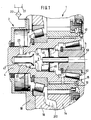
- FIG. 1 shows a partial section of a gear 1 in the area of the input shaft 4, which is mounted in the gear housing 16 via bearings 12.
- a lubricant pump 2 is driven by this shaft, which is arranged in a housing part 18 and sucks the lubricant from a container 21 primarily from the sump 210 of the transmission via a filter 22 and leads via the channel 23 into a rotation space 3.
- the rotation space 3 extends in the longitudinal direction of the transmission input shaft 4 and widens to the largest possible diameter, which is relatively large in diameter due to a molded-on synchronizer body 43. On the face side, in the direction of the transmission, this rotation space is closed off by a body 46, in the middle of which a drain pipe 41 is formed or fastened.
- This body 46 as shown in the half section, z. B. consist of a plastic part in which the drain pipe 41 is contained in one piece. But it can also be a sheet metal part 47 on which the tube 41 is held.
- the tube 41 projects into a central bore 53 of a main transmission shaft 5, which is supported by its journal 51 and the bearing 52 in the transmission input shaft 4.
- a pipe 42 with a funnel-shaped end 420 projects into the rotation space, and the drain pipe 41 also protrudes from the body 46 or the sheet metal part 47 in the direction of the rotation space.
- needle bearing 15 is also a gear 13 which meshes with a gear 14 arranged on the countershaft.
- the rotation space 3 is arranged in the input shaft 4.
- the lubricant pump is on the not shown Is arranged countershaft, the lubricant and coolant is supplied via a channel 17 arranged in the transmission housing 16 to an annular space 48 formed in the transmission input shaft 4, from which a channel 49 emanates, which opens into the rotation space, wherein, as shown in FIG. this channel 49 is arranged tangentially 490 to the lateral surface 34.
- a lubricant pump 2 draws in lubricant from a container 21 or from a sump 210 through a filter 22 and leads it into the rotation space 3 via the channel 23 (FIG. 1) or 49 (FIGS. 2 and 3). From the tube 42 with the funnel-shaped end (widening) 420, the lubricant is deflected in the direction of the jacket 31 of the rotation space and moves in the annular space 33 with a simultaneous slowdown of the flow due to the cross-sectional widening in the axial direction towards the discharge pipe 41.
- the lubricant is also set in rotation and the impurities are thrown onto the outer surface.
- the cleaned lubricant is then discharged via the tube 41 and the bearings z. B. 52, 15 and 12 in a known manner.
- a solid film of dirt forms on the lateral surface 31, which adheres even when the transmission is at a standstill.
- a ring magnet 45 can also be arranged on the outer surface 31 or a part of this outer surface.
Landscapes
- Engineering & Computer Science (AREA)
- General Engineering & Computer Science (AREA)
- Mechanical Engineering (AREA)
- General Details Of Gearings (AREA)
Abstract
Claims (7)
Applications Claiming Priority (2)
| Application Number | Priority Date | Filing Date | Title |
|---|---|---|---|
| DE3722392 | 1987-07-07 | ||
| DE3722392 | 1987-07-07 |
Publications (2)
| Publication Number | Publication Date |
|---|---|
| EP0365574A1 EP0365574A1 (fr) | 1990-05-02 |
| EP0365574B1 true EP0365574B1 (fr) | 1992-03-11 |
Family
ID=6331058
Family Applications (1)
| Application Number | Title | Priority Date | Filing Date |
|---|---|---|---|
| EP19880905791 Expired - Lifetime EP0365574B1 (fr) | 1987-07-07 | 1988-06-30 | Dispositif de nettoyage d'huiles lubrifiantes dansdes boites de vitesses |
Country Status (5)
| Country | Link |
|---|---|
| US (1) | US5005437A (fr) |
| EP (1) | EP0365574B1 (fr) |
| JP (1) | JPH02502664A (fr) |
| DE (1) | DE3869134D1 (fr) |
| WO (1) | WO1989000260A1 (fr) |
Cited By (2)
| Publication number | Priority date | Publication date | Assignee | Title |
|---|---|---|---|---|
| DE102009002181A1 (de) | 2009-04-03 | 2010-10-14 | Zf Friedrichshafen Ag | Getriebeanordnung für ein Fahrzeug |
| DE102014019120A1 (de) | 2014-12-19 | 2016-06-23 | Daimler Ag | Hohlwelle für einen Kraftwagen |
Families Citing this family (15)
| Publication number | Priority date | Publication date | Assignee | Title |
|---|---|---|---|---|
| US5279391A (en) * | 1993-02-03 | 1994-01-18 | Eaton Corporation | Dry sump mechanical transmission |
| US5667036A (en) * | 1996-05-21 | 1997-09-16 | New Venture Gear, Inc. | Lubrication system for transmissions |
| GB9711164D0 (en) * | 1997-05-31 | 1997-07-23 | Agco Limited | Vehicle transmission lubrication system |
| US5810116A (en) * | 1997-06-04 | 1998-09-22 | New Venture Gear, Inc. | Bearing lubrication mechanism |
| US5801262A (en) * | 1997-06-30 | 1998-09-01 | General Electric Company | Process for preparing polysiloxane microspheres with a narrow size distribution |
| JP2001200988A (ja) * | 2000-01-17 | 2001-07-27 | Honda Motor Co Ltd | 油供給装置 |
| US6875111B1 (en) * | 2001-09-06 | 2005-04-05 | Sennax Industries, Inc. | Intermediate shaft assembly |
| US7285052B1 (en) | 2002-08-19 | 2007-10-23 | Sennax Industries, Inc. | Intermediate shaft assembly |
| US20050026031A1 (en) * | 2003-08-01 | 2005-02-03 | Mckenzie Rodney S. | Nickel-plated screen for electrochemical cell |
| DE102004062067B4 (de) * | 2004-12-23 | 2017-06-08 | Schaeffler Technologies AG & Co. KG | Vorrichtung zur Veränderung der Steuerzeiten einer Brennkraftmaschine |
| US20120240708A1 (en) * | 2011-03-21 | 2012-09-27 | Voth Danny G | Power Transfer Box Spline Lubrication Device |
| DE102012214771B4 (de) * | 2012-08-20 | 2019-11-21 | Schaeffler Technologies AG & Co. KG | Steckwellensystem und Differenzial mit Steckwellensystem |
| JP6245647B2 (ja) * | 2014-04-23 | 2017-12-13 | 本田技研工業株式会社 | 変速機のベアリング潤滑構造 |
| US9835241B2 (en) | 2014-07-23 | 2017-12-05 | Horizon Value Services, Inc. | System and process for removing hardened lubricant from an enclosed gearbox |
| CN111250796B (zh) * | 2020-03-03 | 2023-03-10 | 重庆华陵工业有限公司 | 一种变速箱内部齿轮生产自动去杂无尘剃齿装置 |
Family Cites Families (10)
| Publication number | Priority date | Publication date | Assignee | Title |
|---|---|---|---|---|
| US2328104A (en) * | 1942-03-30 | 1943-08-31 | Borg Warner | Transmission |
| US2741333A (en) * | 1950-07-12 | 1956-04-10 | Gen Motors Corp | Oil purification |
| CH347040A (it) * | 1956-10-31 | 1960-06-15 | Fiat Spa | Filtro centrifugo, segnatamente per l'olio di lubrificazione di motori a combustione interna |
| US3014634A (en) * | 1958-05-12 | 1961-12-26 | Design Dynamics Inc | Dispensing container |
| US3143187A (en) * | 1963-11-26 | 1964-08-04 | Ford Motor Co | Lubricating system |
| JPS55152952A (en) * | 1979-05-16 | 1980-11-28 | Honda Motor Co Ltd | Centrifugal oil filter for hydraulic transmission |
| JPS5874959A (ja) * | 1981-10-29 | 1983-05-06 | Honda Motor Co Ltd | 歯車伝動系における伝動歯車の潤滑装置 |
| JPS58177652U (ja) * | 1982-05-21 | 1983-11-28 | トヨタ自動車株式会社 | 変速機の潤滑機構 |
| JPS63109261U (fr) * | 1987-01-08 | 1988-07-14 | ||
| US4907951A (en) * | 1988-09-16 | 1990-03-13 | Tecumseh Products Company | Foreign particle trap for a compressor |
-
1988
- 1988-06-30 JP JP63505712A patent/JPH02502664A/ja active Pending
- 1988-06-30 DE DE8888905791T patent/DE3869134D1/de not_active Expired - Lifetime
- 1988-06-30 US US07/445,614 patent/US5005437A/en not_active Expired - Lifetime
- 1988-06-30 EP EP19880905791 patent/EP0365574B1/fr not_active Expired - Lifetime
- 1988-06-30 WO PCT/EP1988/000580 patent/WO1989000260A1/fr not_active Ceased
Non-Patent Citations (1)
| Title |
|---|
| Patent Abstracts of Japan, Band 5, Nr. 25 (M-55)(697), 14. Februar 1981, & JP, A, 55152952 (HONDA GIKEN KOGYO K.K.) 28. November 1980 * |
Cited By (3)
| Publication number | Priority date | Publication date | Assignee | Title |
|---|---|---|---|---|
| DE102009002181A1 (de) | 2009-04-03 | 2010-10-14 | Zf Friedrichshafen Ag | Getriebeanordnung für ein Fahrzeug |
| DE102014019120A1 (de) | 2014-12-19 | 2016-06-23 | Daimler Ag | Hohlwelle für einen Kraftwagen |
| DE102014019120B4 (de) | 2014-12-19 | 2023-12-07 | Daimler Truck AG | Hohlwelle für einen Kraftwagen |
Also Published As
| Publication number | Publication date |
|---|---|
| US5005437A (en) | 1991-04-09 |
| DE3869134D1 (de) | 1992-04-16 |
| WO1989000260A1 (fr) | 1989-01-12 |
| JPH02502664A (ja) | 1990-08-23 |
| EP0365574A1 (fr) | 1990-05-02 |
Similar Documents
| Publication | Publication Date | Title |
|---|---|---|
| EP0365574B1 (fr) | Dispositif de nettoyage d'huiles lubrifiantes dansdes boites de vitesses | |
| DE2839233C2 (fr) | ||
| DE19860092C2 (de) | Getriebe mit einer Schmiervorrichtung | |
| DE3015681C2 (de) | Schmiervorrichtung für ein Radiallager | |
| DE1959585C3 (de) | Schmiervorrichtung für ein Kegelrad- Planetengetriebe | |
| DE2915706A1 (de) | Getriebe mit einer schmieranlage | |
| DE112011100148T5 (de) | Kraftübertragungsvorrichtung | |
| DE102005021095B9 (de) | Partitionsstruktur einer Kraftübertragungsvorrichtung | |
| DE3238780C1 (de) | Ölschmiersystem für Getriebe | |
| EP0353445A2 (fr) | Palier lubrifié à rouleaux cylindriques pour axe horizontal | |
| DE3905770A1 (de) | Verfahren und vorrichtung zur reinigung von schmieroel im getriebe | |
| WO2023131516A1 (fr) | Ensemble comprenant une transmission de jeu de pédalier pour une bicyclette ou un vélo à assistance électrique | |
| DE2857678C2 (de) | Schmiervorrichtung für die Lager von Getrieben | |
| AT393875B (de) | Ausgleichsgetriebe | |
| DE102015219431A1 (de) | Beölungsvorrichtung für Getriebe | |
| DE3600871C2 (fr) | ||
| WO2023169778A1 (fr) | Dispositif de transmission pour un véhicule à moteur, et véhicule équipé du dispositif de transmission | |
| DE102010005749A1 (de) | Maschine mit Schmierstoffkreislauf | |
| DE4434020B4 (de) | Stufenloses Umschlingsungsgetriebe mit einer Sumpfölfördereinrichtung | |
| DE4131164A1 (de) | Vorrichtung zur lagerschmierung | |
| DE3921932C2 (fr) | ||
| DE102004032227A1 (de) | Schmierungsstruktur eines Handschaltgetriebes | |
| DE3506089C2 (fr) | ||
| DE1273914B (de) | Schmiervorrichtung an einem Zahnrad | |
| DE102009027534A1 (de) | Schmiermittelversorgungssystem, insbesondere für ein Kraftfahrzeuggetriebe |
Legal Events
| Date | Code | Title | Description |
|---|---|---|---|
| PUAI | Public reference made under article 153(3) epc to a published international application that has entered the european phase |
Free format text: ORIGINAL CODE: 0009012 |
|
| 17P | Request for examination filed |
Effective date: 19891104 |
|
| AK | Designated contracting states |
Kind code of ref document: A1 Designated state(s): DE GB |
|
| 17Q | First examination report despatched |
Effective date: 19910827 |
|
| GRAA | (expected) grant |
Free format text: ORIGINAL CODE: 0009210 |
|
| AK | Designated contracting states |
Kind code of ref document: B1 Designated state(s): DE GB |
|
| RAP4 | Party data changed (patent owner data changed or rights of a patent transferred) |
Owner name: ZF FRIEDRICHSHAFEN AKTIENGESELLSCHAFT |
|
| REF | Corresponds to: |
Ref document number: 3869134 Country of ref document: DE Date of ref document: 19920416 |
|
| GBT | Gb: translation of ep patent filed (gb section 77(6)(a)/1977) | ||
| PLBE | No opposition filed within time limit |
Free format text: ORIGINAL CODE: 0009261 |
|
| STAA | Information on the status of an ep patent application or granted ep patent |
Free format text: STATUS: NO OPPOSITION FILED WITHIN TIME LIMIT |
|
| 26N | No opposition filed | ||
| PGFP | Annual fee paid to national office [announced via postgrant information from national office to epo] |
Ref country code: GB Payment date: 19980526 Year of fee payment: 11 |
|
| PG25 | Lapsed in a contracting state [announced via postgrant information from national office to epo] |
Ref country code: GB Free format text: LAPSE BECAUSE OF NON-PAYMENT OF DUE FEES Effective date: 19990630 |
|
| GBPC | Gb: european patent ceased through non-payment of renewal fee |
Effective date: 19990630 |
|
| PGFP | Annual fee paid to national office [announced via postgrant information from national office to epo] |
Ref country code: DE Payment date: 20070628 Year of fee payment: 20 |