EP0365592B1 - Couvercle de fermeture avec joint d'etancheite et procede de formation de ce joint - Google Patents
Couvercle de fermeture avec joint d'etancheite et procede de formation de ce joint Download PDFInfo
- Publication number
- EP0365592B1 EP0365592B1 EP88906358A EP88906358A EP0365592B1 EP 0365592 B1 EP0365592 B1 EP 0365592B1 EP 88906358 A EP88906358 A EP 88906358A EP 88906358 A EP88906358 A EP 88906358A EP 0365592 B1 EP0365592 B1 EP 0365592B1
- Authority
- EP
- European Patent Office
- Prior art keywords
- seal
- cap
- plastic
- sealing
- linerless
- Prior art date
- Legal status (The legal status is an assumption and is not a legal conclusion. Google has not performed a legal analysis and makes no representation as to the accuracy of the status listed.)
- Expired - Lifetime
Links
- 238000000034 method Methods 0.000 title claims abstract description 27
- 238000007789 sealing Methods 0.000 claims abstract description 175
- 229920003023 plastic Polymers 0.000 claims abstract description 89
- 239000004033 plastic Substances 0.000 claims abstract description 89
- 229910052760 oxygen Inorganic materials 0.000 claims abstract description 3
- 229920000642 polymer Polymers 0.000 claims description 7
- 239000011521 glass Substances 0.000 claims description 3
- 239000011148 porous material Substances 0.000 claims 1
- 210000003739 neck Anatomy 0.000 description 76
- 230000006835 compression Effects 0.000 description 33
- 238000007906 compression Methods 0.000 description 33
- 238000004519 manufacturing process Methods 0.000 description 19
- 239000000463 material Substances 0.000 description 12
- 230000008901 benefit Effects 0.000 description 11
- 230000015572 biosynthetic process Effects 0.000 description 11
- 239000000758 substrate Substances 0.000 description 11
- 238000013461 design Methods 0.000 description 9
- -1 polypropylene Polymers 0.000 description 8
- 238000000465 moulding Methods 0.000 description 7
- 239000004743 Polypropylene Substances 0.000 description 6
- 230000009471 action Effects 0.000 description 6
- 239000002184 metal Substances 0.000 description 6
- 229910052751 metal Inorganic materials 0.000 description 6
- 229920001155 polypropylene Polymers 0.000 description 6
- 238000009826 distribution Methods 0.000 description 5
- 230000009467 reduction Effects 0.000 description 5
- 230000004075 alteration Effects 0.000 description 4
- 238000011161 development Methods 0.000 description 4
- 238000006073 displacement reaction Methods 0.000 description 4
- 239000007924 injection Substances 0.000 description 4
- 230000000704 physical effect Effects 0.000 description 4
- 238000013459 approach Methods 0.000 description 3
- 235000013361 beverage Nutrition 0.000 description 3
- 238000010276 construction Methods 0.000 description 3
- 229920001577 copolymer Polymers 0.000 description 3
- 230000007547 defect Effects 0.000 description 3
- 230000006870 function Effects 0.000 description 3
- 238000002347 injection Methods 0.000 description 3
- 238000002844 melting Methods 0.000 description 3
- 230000008018 melting Effects 0.000 description 3
- 230000002093 peripheral effect Effects 0.000 description 3
- 238000007493 shaping process Methods 0.000 description 3
- 239000004698 Polyethylene Substances 0.000 description 2
- 239000004793 Polystyrene Substances 0.000 description 2
- 230000000996 additive effect Effects 0.000 description 2
- 238000004458 analytical method Methods 0.000 description 2
- 230000009286 beneficial effect Effects 0.000 description 2
- 230000000694 effects Effects 0.000 description 2
- 235000013305 food Nutrition 0.000 description 2
- 239000011796 hollow space material Substances 0.000 description 2
- 230000000977 initiatory effect Effects 0.000 description 2
- 238000001746 injection moulding Methods 0.000 description 2
- 230000004048 modification Effects 0.000 description 2
- 238000012986 modification Methods 0.000 description 2
- 229920000573 polyethylene Polymers 0.000 description 2
- 229920002223 polystyrene Polymers 0.000 description 2
- 239000004800 polyvinyl chloride Substances 0.000 description 2
- 229920000915 polyvinyl chloride Polymers 0.000 description 2
- QQONPFPTGQHPMA-UHFFFAOYSA-N propylene Natural products CC=C QQONPFPTGQHPMA-UHFFFAOYSA-N 0.000 description 2
- 238000002407 reforming Methods 0.000 description 2
- 238000012360 testing method Methods 0.000 description 2
- 241000283690 Bos taurus Species 0.000 description 1
- 235000005979 Citrus limon Nutrition 0.000 description 1
- 244000131522 Citrus pyriformis Species 0.000 description 1
- 240000008415 Lactuca sativa Species 0.000 description 1
- 229920001944 Plastisol Polymers 0.000 description 1
- XECAHXYUAAWDEL-UHFFFAOYSA-N acrylonitrile butadiene styrene Chemical compound C=CC=C.C=CC#N.C=CC1=CC=CC=C1 XECAHXYUAAWDEL-UHFFFAOYSA-N 0.000 description 1
- 239000000654 additive Substances 0.000 description 1
- 239000000956 alloy Substances 0.000 description 1
- 229910045601 alloy Inorganic materials 0.000 description 1
- 238000000137 annealing Methods 0.000 description 1
- QVGXLLKOCUKJST-UHFFFAOYSA-N atomic oxygen Chemical compound [O] QVGXLLKOCUKJST-UHFFFAOYSA-N 0.000 description 1
- 230000004888 barrier function Effects 0.000 description 1
- 235000013405 beer Nutrition 0.000 description 1
- 230000006399 behavior Effects 0.000 description 1
- 235000012174 carbonated soft drink Nutrition 0.000 description 1
- 230000005465 channeling Effects 0.000 description 1
- 238000004891 communication Methods 0.000 description 1
- 238000000748 compression moulding Methods 0.000 description 1
- 238000001816 cooling Methods 0.000 description 1
- 239000002537 cosmetic Substances 0.000 description 1
- 230000003811 curling process Effects 0.000 description 1
- 238000005034 decoration Methods 0.000 description 1
- 230000007812 deficiency Effects 0.000 description 1
- 239000003599 detergent Substances 0.000 description 1
- 230000001627 detrimental effect Effects 0.000 description 1
- 239000003814 drug Substances 0.000 description 1
- 229940079593 drug Drugs 0.000 description 1
- 229920001971 elastomer Polymers 0.000 description 1
- 230000008030 elimination Effects 0.000 description 1
- 238000003379 elimination reaction Methods 0.000 description 1
- 238000005516 engineering process Methods 0.000 description 1
- 210000003414 extremity Anatomy 0.000 description 1
- 235000011389 fruit/vegetable juice Nutrition 0.000 description 1
- 238000010438 heat treatment Methods 0.000 description 1
- 239000003845 household chemical Substances 0.000 description 1
- 230000006872 improvement Effects 0.000 description 1
- 230000007774 longterm Effects 0.000 description 1
- 210000003141 lower extremity Anatomy 0.000 description 1
- 238000012423 maintenance Methods 0.000 description 1
- 235000010746 mayonnaise Nutrition 0.000 description 1
- 239000008268 mayonnaise Substances 0.000 description 1
- 230000007246 mechanism Effects 0.000 description 1
- 239000000203 mixture Substances 0.000 description 1
- 230000007935 neutral effect Effects 0.000 description 1
- 229920001778 nylon Polymers 0.000 description 1
- 239000002674 ointment Substances 0.000 description 1
- 239000001301 oxygen Substances 0.000 description 1
- 239000011087 paperboard Substances 0.000 description 1
- 238000009928 pasteurization Methods 0.000 description 1
- 235000021400 peanut butter Nutrition 0.000 description 1
- 239000004999 plastisol Substances 0.000 description 1
- 229920002587 poly(1,3-butadiene) polymer Polymers 0.000 description 1
- 229920001200 poly(ethylene-vinyl acetate) Polymers 0.000 description 1
- 229920002492 poly(sulfone) Polymers 0.000 description 1
- 229920000515 polycarbonate Polymers 0.000 description 1
- 239000004417 polycarbonate Substances 0.000 description 1
- 229920000728 polyester Polymers 0.000 description 1
- 229920000098 polyolefin Polymers 0.000 description 1
- 238000003825 pressing Methods 0.000 description 1
- 230000008569 process Effects 0.000 description 1
- 238000011084 recovery Methods 0.000 description 1
- 230000002787 reinforcement Effects 0.000 description 1
- 230000003014 reinforcing effect Effects 0.000 description 1
- 230000004044 response Effects 0.000 description 1
- 230000000452 restraining effect Effects 0.000 description 1
- 239000005060 rubber Substances 0.000 description 1
- 235000012045 salad Nutrition 0.000 description 1
- 238000009987 spinning Methods 0.000 description 1
- 230000003068 static effect Effects 0.000 description 1
- 238000009827 uniform distribution Methods 0.000 description 1
- 235000021419 vinegar Nutrition 0.000 description 1
- 239000000052 vinegar Substances 0.000 description 1
- 239000011800 void material Substances 0.000 description 1
- 239000004636 vulcanized rubber Substances 0.000 description 1
Images


Classifications
-
- B—PERFORMING OPERATIONS; TRANSPORTING
- B29—WORKING OF PLASTICS; WORKING OF SUBSTANCES IN A PLASTIC STATE IN GENERAL
- B29C—SHAPING OR JOINING OF PLASTICS; SHAPING OF MATERIAL IN A PLASTIC STATE, NOT OTHERWISE PROVIDED FOR; AFTER-TREATMENT OF THE SHAPED PRODUCTS, e.g. REPAIRING
- B29C67/00—Shaping techniques not covered by groups B29C39/00 - B29C65/00, B29C70/00 or B29C73/00
-
- B—PERFORMING OPERATIONS; TRANSPORTING
- B29—WORKING OF PLASTICS; WORKING OF SUBSTANCES IN A PLASTIC STATE IN GENERAL
- B29C—SHAPING OR JOINING OF PLASTICS; SHAPING OF MATERIAL IN A PLASTIC STATE, NOT OTHERWISE PROVIDED FOR; AFTER-TREATMENT OF THE SHAPED PRODUCTS, e.g. REPAIRING
- B29C55/00—Shaping by stretching, e.g. drawing through a die; Apparatus therefor
-
- B—PERFORMING OPERATIONS; TRANSPORTING
- B29—WORKING OF PLASTICS; WORKING OF SUBSTANCES IN A PLASTIC STATE IN GENERAL
- B29C—SHAPING OR JOINING OF PLASTICS; SHAPING OF MATERIAL IN A PLASTIC STATE, NOT OTHERWISE PROVIDED FOR; AFTER-TREATMENT OF THE SHAPED PRODUCTS, e.g. REPAIRING
- B29C57/00—Shaping of tube ends, e.g. flanging, belling or closing; Apparatus therefor, e.g. collapsible mandrels
- B29C57/12—Rim rolling
-
- B—PERFORMING OPERATIONS; TRANSPORTING
- B65—CONVEYING; PACKING; STORING; HANDLING THIN OR FILAMENTARY MATERIAL
- B65D—CONTAINERS FOR STORAGE OR TRANSPORT OF ARTICLES OR MATERIALS, e.g. BAGS, BARRELS, BOTTLES, BOXES, CANS, CARTONS, CRATES, DRUMS, JARS, TANKS, HOPPERS, FORWARDING CONTAINERS; ACCESSORIES, CLOSURES, OR FITTINGS THEREFOR; PACKAGING ELEMENTS; PACKAGES
- B65D41/00—Caps, e.g. crown caps or crown seals, i.e. members having parts arranged for engagement with the external periphery of a neck or wall defining a pouring opening or discharge aperture; Protective cap-like covers for closure members, e.g. decorative covers of metal foil or paper
- B65D41/02—Caps or cap-like covers without lines of weakness, tearing strips, tags, or like opening or removal devices
- B65D41/04—Threaded or like caps or cap-like covers secured by rotation
- B65D41/0407—Threaded or like caps or cap-like covers secured by rotation with integral sealing means
- B65D41/0414—Threaded or like caps or cap-like covers secured by rotation with integral sealing means formed by a plug, collar, flange, rib or the like contacting the internal surface of a container neck
-
- B—PERFORMING OPERATIONS; TRANSPORTING
- B65—CONVEYING; PACKING; STORING; HANDLING THIN OR FILAMENTARY MATERIAL
- B65D—CONTAINERS FOR STORAGE OR TRANSPORT OF ARTICLES OR MATERIALS, e.g. BAGS, BARRELS, BOTTLES, BOXES, CANS, CARTONS, CRATES, DRUMS, JARS, TANKS, HOPPERS, FORWARDING CONTAINERS; ACCESSORIES, CLOSURES, OR FITTINGS THEREFOR; PACKAGING ELEMENTS; PACKAGES
- B65D41/00—Caps, e.g. crown caps or crown seals, i.e. members having parts arranged for engagement with the external periphery of a neck or wall defining a pouring opening or discharge aperture; Protective cap-like covers for closure members, e.g. decorative covers of metal foil or paper
- B65D41/32—Caps or cap-like covers with lines of weakness, tearing-strips, tags, or like opening or removal devices, e.g. to facilitate formation of pouring openings
- B65D41/34—Threaded or like caps or cap-like covers provided with tamper elements formed in, or attached to, the closure skirt
- B65D41/3442—Threaded or like caps or cap-like covers provided with tamper elements formed in, or attached to, the closure skirt with rigid bead or projections formed on the tamper element and coacting with bead or projections on the container
- B65D41/3447—Threaded or like caps or cap-like covers provided with tamper elements formed in, or attached to, the closure skirt with rigid bead or projections formed on the tamper element and coacting with bead or projections on the container the tamper element being integrally connected to the closure by means of bridges
-
- B—PERFORMING OPERATIONS; TRANSPORTING
- B29—WORKING OF PLASTICS; WORKING OF SUBSTANCES IN A PLASTIC STATE IN GENERAL
- B29L—INDEXING SCHEME ASSOCIATED WITH SUBCLASS B29C, RELATING TO PARTICULAR ARTICLES
- B29L2031/00—Other particular articles
- B29L2031/26—Sealing devices, e.g. packaging for pistons or pipe joints
-
- B—PERFORMING OPERATIONS; TRANSPORTING
- B29—WORKING OF PLASTICS; WORKING OF SUBSTANCES IN A PLASTIC STATE IN GENERAL
- B29L—INDEXING SCHEME ASSOCIATED WITH SUBCLASS B29C, RELATING TO PARTICULAR ARTICLES
- B29L2031/00—Other particular articles
- B29L2031/56—Stoppers or lids for bottles, jars, or the like, e.g. closures
- B29L2031/565—Stoppers or lids for bottles, jars, or the like, e.g. closures for containers
-
- Y—GENERAL TAGGING OF NEW TECHNOLOGICAL DEVELOPMENTS; GENERAL TAGGING OF CROSS-SECTIONAL TECHNOLOGIES SPANNING OVER SEVERAL SECTIONS OF THE IPC; TECHNICAL SUBJECTS COVERED BY FORMER USPC CROSS-REFERENCE ART COLLECTIONS [XRACs] AND DIGESTS
- Y10—TECHNICAL SUBJECTS COVERED BY FORMER USPC
- Y10S—TECHNICAL SUBJECTS COVERED BY FORMER USPC CROSS-REFERENCE ART COLLECTIONS [XRACs] AND DIGESTS
- Y10S215/00—Bottles and jars
- Y10S215/01—Fins
Definitions
- This invention relates to a method for forming a cap having a linerless plastic seal, a cap formed by said method, a cap for a container, and such a cap in combination with a container.
- the liner may be preformed from sheet or formed in place and is produced from materials or laminar combinations or materials which provide easy cold formability to enable the liner to conform to the individual configuration of the neck rim, including manufacturing aberrations and defects. Because of the specialized sealing function of a liner, it is typically made from softer polymers than those selected to perform the more structural cap functions of providing a strong resilient enclosure for the neck opening with a strong mechanical engagement therewith. In some instances stiffer and stronger polymers, including some which are suitable for producing threaded caps, may be foamed to produce an expanded, less dense sheet having a softer, more flexible characteristics and liners may be made therefrom.
- An ideal liner therefore, would possess a soft, easily conformable sealing surface, backed by a resilient supporting structure having good resistance to plastic creep to assure a good sealing engagement at all times under all conditions.
- Such an ideal liner could be vulcanized rubber which can possess both softness and resiliency over long time periods.
- plastics which are suitably soft exhibit poor long term creep resistance and resilience.
- An alternative approach in popular use is a laminate of a springy paperboard substrate with a soft conformable sealing surface such as wax or plastic. However, this approach has significant performance limitations especially when moisture is present.
- cap liners add another component to the closure and significantly add to its cost.
- caps which have an integral, "linerless” seal.
- semi-rigid plastics as polypropylene and polyethylene, which combine a moderate level of strength and resilience with a moderate level of softness and conformability, has made possible popular use of caps with linerless seals.
- such caps employ a circular flange under the cap lid having a wedge shape cross section the lower corner of which is thin and flexible and intended to abut the top surface of the bottle neck rim in a compressive action for sealing.
- the wedge shape flange generally is vertical and provides a sealing area restricted to the width of the narrow, more flexible portion of the wedge shape. For their effective use, they depend upon a very high level of sealing force on a very limited sealing area which makes them susceptible to sealing surface imperfections, wide dimensional variations in container necks and the decay of sealing force over long time periods.
- Some other linerless caps employ comical flanges which engage the corners of the neck rim with the underside of the flange. Such features rely on the use of very high sealing pressure directed against a restricted line contact at the rim corners to obtain sealing integrity. In such cases, sealing integrity depends on container rim corners which are without blemishes as produced and which, because they are most susceptible to marring during handling, are suitably protected from such before they are capped and sealed. Also, to the extent that the comical flanges approach the shape of a cylinder, their sealing integrity is significantly affected by out-of-round or other common dimensional variations of the container manufacturing process or variations between manufacturers resulting from the fact that inside neck dimensions typically are not specified. And to the extent that the flanges become more comical, more complex and costly mold contructions and operation result.
- Still another type of linerless cap employs a plug configuration in sealing contact with the inside wall of the container neck.
- This type of seal has the advantage of engaging that surface of the bottle neck which may be freest from manufacturing defects and most protected from incidental marring in handling thereafter.
- wide manufacturing dimensional tolerances and the industry-wide practice of not specifying the neck bore dimension impose severe limitations in trying to obtain consistent sealing engagement and integrity.
- resistance to tapered plug seals can push the cap lid up to varying degrees of undesirable dome shapes.
- plug seals can yield unacceptably wide variations in sealing engagement and pressures.
- Another effort to avoid distortion of the lip or rim of such a seal is a cap design and method of producing it wherein a radially extending flange having a downward orientation as molded is hingedly "bent", “folded” or inverted into an upward orientation before it is applied to the container (see US-A- 4 210 251 and GB-A- 1 024 762). This is accomplished with extra mold portions and actions during part removal or subsequently in an appropriate fixture to hingedly invert the flange.
- This effort therefore, requires the molding of a seal of complex shape utilizing a complicated and costly mold construction and molding operations followed by inverting the sealing portion of the seal hingedly to alter its orientation but not its shape.
- an inherent limitation to heretofore available linerless caps is that the sealing surface has the same plastic in the same physical state as the structural portion of the cap. This has called for a compromise in the softness and conformability of the sealing surface or in the strength of the structural cap portions, or most frequently both, with consequent limitations in the cap usefulness. That is, to achieve a softer more conformable seal, poorer thread strength must be accepted or to achieve greater thread strength, a harder, less conformable seal must be accepted.
- the linerless sealing surface is made relatively softer than the other cap portions as a result of altering it by stretching to produce microscopic voids employing plastics having this characteristic.
- a new and unique cap with a seal which develops and maintains a positive sealing pressure and engagement with a container opening throughout the shelf life of the contained product and upon opening and resealing the container.
- the cap is substantially rigid and includes plastic material and generally has a top wall or lid which covers the container opening.
- the cap has a depending skirt which engages the finish of a container or bottle for opening and closing thereof.
- the seal is made from plastic and depends from the top wall of the cap.
- the seal preferably is internally spaced from the peripheral skirt and includes an upper end depending from the top wall and a free end with a highly resilient and compressible curled portion which preferably has a relatively soft and conformable sealing surface.
- a curvilinear portion of the seal engages the container finish and readily compresses to provide a relatively large sealing area to seal the contained product.
- the cap is linerless with the seal integral with the top wall of the cap.
- the linerless seal includes a substantially annular upper portion integral with and depending from the lid and a substantially annular highly compressible curled free end which defines a hollow "O" or coiled ring.
- the hollowness of the curled "O" shape and relative thinness imparts a high degree of compressibility as well as the ability to recover from such compression.
- the coiled configuration of the hollow "O" shape which is affixed to the top wall of the cap at one end and free at its other end, imparts a further degree of compressibility and recovery.
- the curled "O" shape includes an arc of from 270 to 360 degrees.
- the compressibility of the hollow annular "O" ring is highly advantageous in its ability to adjust to neck dimension variations and out-of-round conditions prevalent in container or bottle manufacturing processes.
- the "0" ring shape of the seal not only accommodates to such manufacturing variability, but does so without excessive variations in sealing pressure and associated capping, uncapping and sealing difficulties. Because of the low variation in sealing pressure possible with the present invention, lower levels of sealing pressure may be employed while maintaining an adequate minimum pressure to assure a proper seal.
- Such low sealing pressure allows the plastic material to operate more within its elastic limits thereby contributing directly to relatively low loss of such pressure over long shelf life periods or through accelerated conditions, such as pasteurization processes, which cause creep, i.e., plastic cold flow.
- the high compressibility of the seal presents the advantage of being able to use a single cap for different bottles of the same nominal size and engagement means even though different bottle materials (glass, various plastics) and associated neck bore diameters may be used.
- Another aspect of the present invention is the location of the curled or curvilinear portion of the seal at or near the sealing contact area. Whether the curled portion is in the shape of an "O" ring, coil or other similar shapes, such as "U” or "J", this feature of the invention enables the sealing surface to adjust to the container both radially and axially. In turn, this contributes to lower localized stress and deformation with the desirable result of lowering plastic creep.
- the seal includes a relatively large sealing area and high levels of resilience, compressibility and resistance to plastic creep.
- a further contribution of the invention toward maintaining sealing integrity under use conditions comes from the extensive use of curvilinear cross sections in the seal supporting structure which results in more uniform distribution of sealing stresses over larger areas, including portions well removed from sealing contact, and the resultant reduction in localized stresses which cause localized plastic creep.
- the integral seals of the invention can be a rim seal which engages the top surface or rim of the neck finish, a plug seal which abuts and seals the bore of the container neck, or a corner seal which engages the rim and adjacent depending surface of the container neck.
- the curled portion can face outwardly or inwardly.
- the stretched linerless seal preferably has balanced residual strain wherein the plastic at the sealing surface is in a state of tension and relatively soft and compressible and the substrate or supporting structure is in a balancing state of compression and relatively hard and resistant to compression and which maintains the state of tension and relative softness of the opposing sealing surface.
- the linerless seal includes a substantially annular upper portion integral with and depending from the lid and a substantially annular highly compressible curled lower portion which his a "J", "U”, “O” or coiled cross section.
- the curled lower portion has a sealing surface which is softer than the rest of the cap as a result of its method of manufacture which includes stretching it.
- the cap and integral seal of this invention is formed first by conventional molding techniques, such as injection or compression molding, with an internal preform for the integral seal.
- the preform includes an annular wall which is spaced inwardly from the peripheral skirt and which is integral with and depends from the lid in an essentially vertical manner.
- the curled lower portion of the integral seal is formed by forming means which engage the wall to form and define the curved sealing surface and which stretches it to achieve the desired softness of preferred embodiments of the invention.
- the curled lower portion is formed by a curling tool which engages the lower free end of the cylindrical preform, and turns it outwardly toward or inwardly from the skirt and then upwardly channeling and altering the direction of such movement over its working surfaces.
- a curling tool which engages the lower free end of the cylindrical preform, and turns it outwardly toward or inwardly from the skirt and then upwardly channeling and altering the direction of such movement over its working surfaces.
- the initiation of the curling action is facilitated by providing a taper to the lower free end of the cylindrical preform.
- the curling action at this point produces a "J" or "U” shape in such free end.
- To produce an "O" or coil shape after leaving the working surface of the tool, the free end takes an upward and inward or outward direction relative to itself, which results from the continuing compression and the stresses imposed by its plastic memory, to complete the formation of a hollow "O" ring.
- the compression of the cylindrical portion can proceed beyond this point and produce a more fully
- the curling tool can be heated and can be used in straight compression with, with or without spinning, or rolled along the free end of the cylindrical portion during its shaping.
- the free end of the cylindrical portion may be curled simultaneously or sequentially.
- the linerless seal can be exposed to elevated tempeatures for short periods before capping to alter its dimensions, shape or character or the preform for the linerless seal can be heat treated for the same purpose.
- the seal produced by the curling method of the present invention includes a relatively soft and conformable plastics sealing surface and a substrate or supporting portion of the same plastic which is relatively stronger, more resilient and creep resistant. This is achieved by producing and controlling strain within the plastic of the integral seal itself .
- the outer sealing surface of the seal is in a state of tension while the inner or supporting substrate is in a state of compression.
- the cap may be made from a multiphase plastic of the invention so that the stretched sealing surface also includes residual microscopic voids which soften it.
- the curled free end where it contacts the depending wall after formation of the O-ring shape, can be welded to said wall to form a sealed hollow space within resulting in a linerless seal having pneumatic sealing qualities.
- the curling operation off the invention may be performed in sequence with or as part off other steps taken in the manufacture of the cap. That is, it may be performed during or consequent to removal from production molds or during or consequent to cap finishing operations such as lid decoration. It also can be performed simultaneously with or consequent to a curling operation to produce a tamper evident separable or breakaway ring as shown in US-A- 4 709 824. Also the curling operation has been demonstrated to be non-critical in respect to unusual control or conditions so that automatic operation to produce uniform product can be used to achieve high quality at low cost.
- cap and preform for the integral seal are first produced in injection molds employing widely accepted and used mold design and technology.
- the simple shape of the cylindrical preform imposes no significant concern, limitation or expenses in mold design and operation.
- Low cost molds employing traditional stripper ejection mechanisms may be used because of the absence of undercuts which otherwise could distort or tear. This also assures short cooling cycles in the mold.
- relative height and diameter of the curled seal is determined in a separate reforming operation so that a single cap as molded, may be used to produce caps which will fit a variety of bottle neck designs where dimensions, such as thread or locking ring heights, wall thickness or internal diameter varies.
- the cost of the curling tools and the curling operation affect overall cap cost very little, enabling the cap manufacturer to take advantage of the economies, of larger scale production for a number of customers or users from fewer and larger production molds.
- the curling methods of the present invention also can produce linerless caps which include a relatively soft and conformable sealing surface of plastice and a substrate or supporting portion of the same plastic which is relatively stronger, more resilient and creep resistant. This is achieved by the curling methods of the present invention which produce stresses in the plastic of the curled portion, wherein the stresses in the outer sealing surface are in a state of tension or extension and the stresses in the inner supporting substrate are in a state of compression.
- An additional feature is that, when using preferred plastics of the invention, softness of the sealing surface is further enhanced by the development of microscopic internal voids produced thereat by the method of the invention.
- Another preferred embodiment of the invention is to locate the "O" ring shape seal or other shape having a curvilinear or curled sealing contact portion in such a relationship to the rim of the bottle neck that upon its compression by the neck during capping it forms a sealing surface on the inside corner of the rim and the surface adjacent to it on the neck rim and vertical wall. In this manner a very positive seal is achieved.
- Another preferred embodiment of the invention is to shape the seal into a "J" shape by abbreviating the extent to which the depending cylindrical cap portion is curled, wherein the sealing surface is the curved or curled lower extremity and the attachment site to the lid is its upper annular extremity.
- the top surface of the bottle neck rim is employed for the sealing engagement using a cap having a "U" shape or semi-circular cross section integral seal, wherein one leg is attached to the cup lid and the other is unattached but adjacent the lid and optional restraint thereon while the lower curvilinear portion serves to provide the sealing surface.
- a cap having a "U" shape or semi-circular cross section integral seal, wherein one leg is attached to the cup lid and the other is unattached but adjacent the lid and optional restraint thereon while the lower curvilinear portion serves to provide the sealing surface.
- a shape can be wide enough in relation to the neck thickness so that after torquing up the cap the highly compressible "U" shape feature can overlap one or both edges of the neck rim.
- the seal can be more fully curled so as to form an "O" ring shape or less fully curled to form a "J" or quarter-round shape, wherein their lower curvilinear or curled portions engage the neck rim top surface.
- a quarter-round seal can be provided, wherein its free end is in engagement with coacting restraining means located on the interior wall of the cap skirt while the curvilinear portion engages the exterior corner of the neck rim.
- a more fully curled seal can be provided so that a coiled ring is achieved which produces added resilience.
- the bottle neck rim can be produced with a concave surface between its inside and outside walls to minimize ovaling of the curled seal to further reduce localized deformation and plastic creep.
- the above described bottle neck rim can be used as the curling tool to postform the curled portion of the seal, thereby combining the curling operation with the capping operation.
- the curled free end may be horizontally displaced from its opposite end which is integral with the top wall by including a relatively straight or generally horizontal portion therebetween. This allows the O-ring seal of the invention to float and compress more freely, without a constraining influence from the portion of the seal which is fixed by its attachment to the top wall.
- cap lid portion bounded by the linerless seal is made of a different material (e.g., metal, another plastic, etc.) with the curled free end itself used to engage the lid prior to capping and then used as well to seal the lid to the cap and the cap to the container upon capping.
- a different material e.g., metal, another plastic, etc.
- the curled free end of the linerless seal may include radial slits away from the sealing surface so that the resilience of the curled free end may be enhanced.
- An important feature of the invention is that it provides conformable, resilient, integral cap seals with superior ability to conform to the neck configuration of individual containers including those with typical manufacturing defects and aberrations.
- Another feature of the invention is that it assures high sealing integrity even when used with container necks having wide manufacturing dimensional tolerances.
- Yet another feature of the linerless seal of the invention is that it provides high sealing integrity over long shelf life periods with products which are pressurized or under vacuum and/or those subjected to elevated temperatures such as when pasteurized.
- Another feature of the invention is the use of the seal forming method to alter and enhance the physical properties of the plastic to provide optimum sealing characteristics.
- Another feature of the invention is that it can employ more rigid plastics than other linerless seal designs.
- An additional important feature of the invention is its low cost manufacturing method using low cost colds and molding operations, fewer and larger molds and an integrated curling operation.
- FIGURES 1 and 2 there is shown a semi-rigid, threaded, plastic cap 10, having a lid 12, a depending peripheral internally threaded skirt 14 and an internal integral or linerless seal 16.
- the illustrated integral seal 16 includes a cylindrical or annular vertical wall 18 having an upper end 20 integral with the lid 12 and a free curved free end 22. As shown, the end 22 of the integral seal 16 is curled outwardly and forms a hollow annulur "O" or coiled ring 24.
- FIGURES 3-5 there is shown a preferred method of forming the curled portion 24 of the seal 16.
- the cap 10 already has been formed by conventional molding techniques, such as injection molding, with a vertical cylindrical or tubular wall 18 having its upper end 20 integral with the lid 12 and with its lower free end 22 ready for curling by the illustrated curling tool 26.
- the taper preferably extends from rim 30 for a distance sufficient to assure a full round curve to the curl 28 adjacent its rim 30.
- the taper may extend a distance of about 1.270 to 1.905 mm (0.050 to 0.075 inches) from the rim 30. As shown in FIGURES 3-5, the free end 22 and the curl 24 are free of abrupt changes in thickness.
- the curled portion 24 of the seal 16 is formed with a curling tool 26, which in FIGURE 3 has been positioned within the cap 10 ready to engage the preformed wall 18 at its lip or rim 30 .
- the curling tool 26 includes a circular or annular groove 28 of a concave cross section suitable for shaping and dimensioning the curled portion 24.
- the forming operation is accomplished by pressing the groove 28 of the tool 26 against the rim 30 of the wall 18.
- the deepest portion 33 of the groove 28 representing the center of its concavity is located outwardly of the cylindrical plane of the wall 18. This is illustrated by the dotted lines 35 of FIGURE 3.
- the groove 28 has a slanted portion 39 inwardly and tangent to its concavity to facilitate centering of the tool and cap.
- the cylindrical sides of the wall 18 are centered within groove 28 by the slanted portions 39 and are then forced outwardly and then upwardly to assume an interim "J" shape as shown in FIGURE 4.
- the rim 30 is forced upwardly out of groove 28, and at the same time is pulled inwardly in response to the stresses developed therein while being shaped by the tool 26, thereby producing the desired "O" ring curl 24 with an attachment site 20 to the lid 12 close to the plane of the inside diameter of its horizontal cross section.
- the tool 26 may be at a temperature of about ambient to about 148.9°C (300 degrees F) but preferably about ambient to about 65.6°C (150 degrees F) for curling cycles of about one-half to three seconds. Lower temperatures and shorter cycles are preferred to maximize the desired strain of the invention imposed by the curling operation on the plastic of the curl 24 as discussed hereinafter with respect to FIGURES 8 to 14.
- the "O" ring seal 16 includes a bottom sealing portion 32, an inside sealing portion 34 and an outside sealing portion 36. Depending on whether a rim, corner or plug seal is desired one or more of these surfaces can be used for sealing engagement with the appropriate portion of a container or bottle neck. In each embodiment a curled or curved portion of the seal 16 is used as a sealing surface.
- FIGURES 6 and 7 there is illustrated the use of the "O" ring linerless seal 16 of FIGURES 1-5 as a plug type seal for a bottle 37 (partially shown) having an externally threaded neck 38, a rim 40 and an opening or bore 42.
- the curled bottom portion 32 of the seal 16 meets the interior annular corner 44 of the rim 40 and the intersecting internal neck wall 46 which forms the bore 42.
- the seal 16 seats itself within the bore 42 with the external side sealing portion 36 in sealing engagement with the wall 46 of the bore 42. This is accomplished because of the rounded bottom portion 32 and the ready compressibility of the "O" ring shape, wherein the compressed side sealing portion 36 of the ovalized seal 16 forms a firm engagement with the wall 46 defining the bore 42.
- a contribution to low localized stresses and low plastic creep by the "O" ring shape 24 of the invention lies in the fact that the curved side portion 36 used for the sealing engagement with the neck inner wall 46 lies between and is supported by both lower and upper curl portions 32 and 29. In this manner the level of sealing stress transferred to each supporting portion is greatly lower then with only one supporting portion, typical of other linerless seals.
- the side portion 36 adjusts to the constraint of wall 46 with resultant compression, the stresses of which are transmitted to and distributed throughout the "O" ring 24.
- the "O" ring 24 responds to such stress by a reduction in both its external and internal diameters of its horizontal cross section in conjunction with an ovaling of its radial cross section.
- an "O" ring curl 24 having an external diameter of 22.86 mm (0.900 inch) and an internal diameter 17.96 mm (0.707 inch) when seated in the bore of a neck having an internal diameter of 21.49 mm (0.846 inch) produced an immediate reduction of 6 percent in its external diameter and a reduction of 1.2 percent in is internal diameter, demonstrating a significant distribution of sealing stresses throughout all portions of the "O" ring seal of the invention.
- the preferred curling method of the invention illustrated by FIGURES 3-5 produces a linerless seal 16 which possesses the desired large sealing area, a high level of resilience and elasticity and a high level of resistance to plastic creep.
- the reforming method modifies the physical properties of the plastic in such a way as to further enhance its sealing characteristics. That is, the plastic at the sealing surface of the seal 16 is made softer and more conformable and at the substrate and supporting portions is made stronger, more resilient and creep resistant as a result of the stresses imposed on the plastic during the curling operation. This enhancement will now be explained in con;unction with reference to FIGURES 8-14.
- the curling operation by imposing an alternative shape on the preformed cylindrical wall, imposes, it is believed, two sets of balanced residual stresses and stress differentials to the resultant shape in the seal 16. That portion of the seal 16 which is stretched is in extension or a state of tension and that portion which is compressed is in a state of compression.
- the level of stress varies with the degree of extension or compression and, as in any static condition, the total amount and direction of each rind of stress balances and maintains the other.
- FIGURE 8 One set of balanced residual stresses occurs in the direction of curl as a result of the extension and compression of the preformed cylindrical wall 18 across its thickness to form the "O" ring or coiled ring shape 24, as shown in FIGURE 8.
- the plastic At and near the convex exterior surface (sealing surface) represented by points B or Y the plastic is stretched in the direction of the curl and is in a state of high residual tension.
- the opposite concave interior surface, represented by points A or Z is compressed in the direction of the curl and is in a state of high residual compression which balances and maintains the state of tension at or near the exterior convex surface.
- FIGURE 9 shows the direction, sum and approximate distribution of these stresses across the thickness of the plastic including the neutral point 0 and points of maximum compression and tension at or near the inner and outer surfaces. In the normal practice of the invention maximum tensile stress will occur over a finite distance from the surface.
- the sum of the compressive stress defined by points AOC equals that of the tensile stress defined by the
- FIGURE 10 there is shown a typical stress-strain curve for a semi-rigid plastic (e.g. polypropylene) suitable for the practice of the invention.
- the conditions of stress and elongation or compression in the direction of curl at points B and A in FIGURE 8 are shown on the curve at typical locations for the practice of the invention (preferably 50% of the elongation to yield and beyond and the corresponding level of compression).
- the dotted lines define that portion of the stress-strain curve wherein point B, representing the sealing surface of the invention, will typically be found near to or well beyond the tensile yield point R.
- FIGURE 10 Also shown in FIGURE 10 is a typical stress-strain curve for a much softer plastic such as ethylene-vinyl acetate copolymers or polyvinyl chloride plastisol which are popularly used for cap liners because of their soft conformable nature.
- a similarity is noted wherein small amounts of stress result in large amounts of deformation which demonstrates the desired softness, conformability and enhanced sealing qualities of the invention.
- the curling process of the invention used to create the desired shape for superior sealing performance also modifies the physical properties of the plastic at the sealing surface from those of a more rigid, unyielding material suitable for overall cap strength and integrity to those of a softer, more yielding and conformable material suitable for improved sealing characteristics.
- a second set of balanced stresses occurs normal to the first set as a result of the increase and/or decrease of the hoop diameter of the cylindrical cap portion 18 of FIGURE 3 when it is postformed or reformed into the "O" ring 24 or other shape of the seal of the invention as shown in FIGURES 4 and 5.
- the cylindrical portion 18 is composed of an integrated stack of hoops, each of which must be expanded radially (stretched) or compressed to produce the reformed shape, then a condition of tension or compression will be imposed on each of the hoops in the resultant shape as shown in FIGURES 11 and 12 (respectively a radial cross section and a horizontal plan view of the seal 16).
- the level of stress is relative to the amount the hoops have been expanded or compressed and tension is highest at point Y, compression is highest at point X and hoop stresses are nil at the intermediate location of the original cylindrical preform 18, points C and D.
- the distribution of stresses imposed by the curling operation of the invention is optimal for the highest performance of the seal 16 resulting in enhanced softness and conformability of the plastic at the sealing surfaces 32 and 36 and in enhanced strength and resilience of the plastic of the substrate and supporting portions represented by points A and Z of the seal 16.
- FIGURES 15 to 17 there is shown a feature of the invention wherein the sealing surface is softened as a result of the production of microscopic voids thereat by employing plastics which form such voids after stretching.
- FIGURE 15 shows the wall 18 integral with lid 12 and including free end 22 prior to curling.
- FIGURE 16 shows the curled free end 24 including microscopic voids 25 produced during the curling operation which preferably is done at ambient temperatures to facilitate the creation of the voids 25.
- the size and/or number of the voids 25 are in relationship to the degree to which the plastic has been stretched.
- FIGURE 16 shows that the void formation is greater where the plastic has been stretched most in the hoop direction at the outside sealing portion 36 while lower surface 32 and upper surface 29 possess microvoids primarily as a result of stretching in the curl direction.
- FIGURE 17 shows the seal 16 employed as a plug seal against the interior neck wall 46 and the compression of the outside sealing portion 36 by the sealing engagement with the resultant elimination of the voids in the seal area.
- Another feature of the invention is that from a single design of molded cap and seal preform, the kind of seal and its dimensions can be varied to adapt to a variety of bottle neck dimensions and bottle materials.
- a molded cap with a cylindrical preform suitable to be used for a plug seal for a plastic bottle can also be used to produce a rim seal for the same or other plastic bottle or a rim seal for a glass bottle simply by employing alternate curling tools.
- the seal height for a rim seal can be readily altered in the curling operation to permit its use on bottles having a variety of thread heights.
- a single injection mold can be used to produce caps to fit a variety of bottle dimensions producing economies of scale in the cap molding and manufacturing operation.
- Still another feature of the invention is that the caps and linerless seals of the invention can be removed and unsealed without blow-off when the contents of the container are under pressure.
- the distance between the under part of lid 12 and the sealing engagement of outside sealing surface 36 should equal no more than 1/2 the pitch of the cap threads - so that at least 1/2 turn of thread engagement remains after the outside sealing surface 36 clears the inside wall 46 of the bore 42 during uncapping. For most caps this dimension would be about 1.52 to 2.29 mm (about 0.060 to 0.090 inches).
- the amount of elastic compression of seal 16 should be no more than 1/2 the pitch of the cap threads - so that at least 1/2 turn of thread engagement remains after the lower sealing surface 32 of seal 16 clears the rim 40 of bottle neck 38.
- This dimension also would be expected to range typically between 1.52 to 2.29 mm (0.060 to 0.090 inches).
- typical dimensions of the "O" ring curl 24 of seal 16 are about 1.02 to 3.81 mm (about 0.040 to 0.150 inches) for the curl diameter and about 0.18 to 0.76 mm (about 0.007 to 0.030 inches) in wall thickness and the radial cross section preferably forms an arc or a continuous curve of at least 180 degrees.
- a plug seal it typically will have an outside diameter at its sealing surface 36 which is 0.51 to 1.52 mm (0.020 to 0.060 inches) larger than the inside wall 46 of neck 38 with larger ranges applicable to larger size caps.
- Preferred dimensions for the curl 24 to provide maximum plastic property enhancement through imposed stresses by practice of the present invention call for maximum wall thickness and minimum curl diameter low curling temperatures and high curling speed.
- Cap sizes typically range from under 20mm to 120mm and bottle and/or jar sizes range from under 56.7g (2 ounce) to 3.63kg (128 ounce) capacity. Larger capacity containers such as drums or kegs are also suitable for the practice of the invention as are smaller vials and other containers.
- Useful plastics which can be used for forming the caps and linerless seals of the invention include polypropylene, polyethylene, polystyrene, acrylonitrile - styrene - butadiene polymers, and many other semo-rigid to rigid plastic materials.
- other plastics employed in the practice of the invention are chosen from the group of plastics which have in common the fact that when stretched beyond their tensile yield point they develop microscopic voids or fissures within the plastic which serve to soften it and make it more compressible, even when residual tensile strain is not present.
- the group of plastics manifesting this behavior includes essentially all polymer classes (e.g., polystyrene, polyvinyl chloride, polyolefins, polycarbonates, polysulfones, polyesters, nylons, etc.) and preferably are selected from the group of plastics known as alloys, blends, multipolymers, multiphase polymers or other nomenclature, many of which are listed in Modern Plastics Encyclopedia, 1986-1987, pages 105 to 111, the entire disclosure of which is incorporated herein by reference.
- propylene copolymers e.g., Shell 7522
- ethylene-propylene copolymers e.g., Himont SB781
- rubber modified polysytrene e.g., Monsanto Lustrex 4300
- Shell 7522 propylene copolymer produces voids in the range from about 0.25 microns to about 3.0 microns.
- the linerless seals of the present invention can be used in a wide variety of caps including combinations with other materials (e.g., caps having metal lid portions or portions utilizing different plastic than that used for the seal).
- Such linerless seals may be used to close and seal a wide variety of containers for a wide variety of products including: beverages, including carbonated soft drinks and pasteurized beverages such as beer; foods, especially those where container sealing performance is critical, including oxygen sensitive ones such as mayonnaise, peanut butter and salad oil, and including corrosive ones such as vinegar, lemon juice; and household chemicals, including bleaches and detergents, drugs and cosmetics and other products requiring the highest integrity seal and reseal under the widest range of distribution and use conditions.
- the linerless seals of the present invention can be used in conjunction with other types of linerless seals including other type seals of the invention and may employ various or all surfaces of the neck 38.
- the linerless seals of the present invention can be used with a wide variety of caps, including snap caps and threaded caps with or without breakaway rings.
- the linerless seals of the present invention can be used with the caps having the breakaway or separable rings disclosed in US-A- 4 709 824.
- FIGURES 18 - 20 there is shown another method of the invention for forming the curled portion 24 of the seal 16, wherein the curl is tighter and stretching is greater relative to FIGURES 1 to 7.
- FIGURE 18 shows the tubular wall 18 has been engaged and turned outwardly by tool component 56a to form a horizontal wall portion 18a.
- the outward horizontal direction of the wall portion 18a upon compression by tool component 56a is assured by an outwardly directed bevel to the free end 22 at rim 30.
- the top surface of interior tool component 56a may beveled outwardly or wall 18 may be molded with a conical or outwardly flaired free end to assure the outward direction of wall portion 18a.
- FIGURE 19 shows how the horizontal wall portion 18a is turned upwardly to produce the relatively tight U-shaped curl 24 by suitably interrupting the travel of tool component 56a and continuing the travel of tool component 56b.
- the curled ring 16 produced by this method, can be a "J", "U” or quarter-round shape by employing suitable dimensions for wall 18 or tool 56 and/or by adjusting the amount of compression of wall 18 by tool 56.
- the cessation of travel of tool component 56a relative to tubular wall 18 and tool component 56b may be abrupt, but preferably it is gradual to facilitate formation of a tightly curled ring 16.
- the preform wall 18 is vertical where the curled portion 24 is produced to achieve the maximum applied curvature and the greatest degree of stretching and softening.
- the tool 56 may be unitary as shown in FIGURE 20 or the tool components 56a and 56b may be employed to do their respective portions of the curling operation at separate work stations.
- Another option is to produce the curled free end 22 inwardly by suitable alteration of the taper of the wall free end 22 and the dimensions and sequence of operation of tool components 56a and 56b.
- the curl of the embodiment of FIGURE 20 is not as tight as shown in FIGURE 19.
- the vertical component 56b is spaced further away from the depending wall 18 then the corresponding vertical component 56b of FIGURE 19.
- the tightness of the curl is readily adjustable.
- FIGURE 21 shows another embodiment of the invention in which the curled free end 24 is horizontally displaced by a generally flat portion 48 from the attachment site of upper end 20 to the lid 12. In this manner the curled free end 24 is completely free to be compressed when used as a rim seal without the reinforcing influences of upper end 20 on its compressibility.
- FIGURE 21 shows the cap 10 as molded, positioned above curling tool 27 prior to curling.
- the curling tool 27 has a groove 28 including a beveled portion 39, a flat portion 41a and a curved portion 41b.
- FIGURE 23 shows the curled free end 24 in compressive sealing engagement with rim 40 of bottleneck 38 wherein the upper end 20 is displaced from the area of sealing engagement.
- the curled free end 24 may be located inwardly from the upper wall portion 20 employing suitable modifications of tool 27.
- FIGURE 24 shows a cap 10, as molded, including a lid 12 having a a central opening 13 bounded by a depending wall 18 with an upper portion 20 and a free end 22.
- the central opening 13 is bounded at the lid 12 upper surface by an inward projection 15.
- Located in the opening 13 is a metal lid portion 50 which abuts the lid inward projection 15 and is bounded by upper wall portion 20.
- FIGURE 25 shows the cap 10 with its metal lid portion 50 after the wall 18 has been curled by the method of the invention as shown in FIGURES 3 to 5 except that the curled portion 24 is inwardly directed so as to fixedly engage the metal lid portion 50 in a sealing engagement.
- the cap 10 is now ready for capping a container and the curled portion 24 of its linerless seal 16 performs a sealing engagement on both the container neck and the cap metal lid portion 50.
- the central lid portion 50 may be made of other materials such as plastic which offer transparency, barrier, cost or other advantages.
- FIGURE 26 shows a wall 18 with its free end partially curled by a tool 26.
- the tool 26 includes an annular groove 28 a portion of which is bounded by an annular tool insert 52 for heating at a high temperature and an insulating portion 51 to allow the remainder of tool 26 to be operated at a lower temperature.
- the free end 22 has a rim 30 which has a reduced thickness which can be heated to a melting temperature more quickly than the remainder of free end 22.
- the heated tool insert 52 is heated to a temperature sufficiently above the melting point of the plastic to melt the rim 30 of reduced thickness but not high enough to melt the thicker succeeding portions of free 22 as it passes in contact with it during curling to form an O-shape 24 of free end 22.
- the melted rim 30 completes its curling it contacts the wall 18 and forms a welded attachment 19 therewith as shown in FIGURE 27.
- the resultant curled free end 24 is thereby prevented from any possibility of being uncurled as well as converted into a pneumatic shape.
- the curled free end 24 may be welded or otherwise bonded by other means after the O-shape cross section has been formed.
- FIGURES 28 to 30A there is shown another embodiment wherein a non-sealing portion of the linerless seal 16 of the invention is slit radially to provide enhanced resilience during a compressive sealing engagement.
- FIGURE 28 shows a cross section of an inwardly curled free end 24 showing a slit 54 on its inner portion 34. The slits serve the purpose of eliminating the hoop strength of inner portion 34 so that resistance to compression occurs primarily in the curl direction.
- FIGURES 29 and 30 show a slitting tool 58 with slitting elements 59 spaced radially about its upper periphery.
- the curled free end 24 is first produced by the method described in FIGURES 3 to 5 and then the slitting tool 58 is brought into engagement with it to produce the slits (see FIGURE 30A).
- the slitted curled free end may be produced having an outward orientation.
- the slits may be produced to extend to the lip 30 after curling or by slitting the wall 18 prior to curling.
- FIGURES 31 to 33 there is shown a snap cap 10 and an integral plug seal 16a wherein the curl 24a is formed by curling tool 26 inwardly and upwardly so that the outside sealing surface 36 is contiguous with the upper end and attachment site 20 of seal 16a.
- the inward direction of the curl 24a is achieved by locating the center of concavity 33 of the curling groove 28 inwardly of the cylindrical plane of wall 18 as illustrated by the dotted lines 35 of FIGURE 31.
- the plane of attachment site 20 must be displaced as much as possible from the plane of the neck wall 46.
- the radial cross section of the curled portion of seal 16a includes an arc or curved portion of from about 90 to about 450 degrees.
- FIGURE 34 there is shown a threaded cap 10 and integral plug seal 16b wherein the curl 24b has been formed by a curling tool 26 (not shown) inwardly and upwardly.
- the hollow interior 48 of the "O" ring is in communication with the interior of the partially shown container 37.
- internal pressure 50 (indicated by arrows) within container 37 is directed toward the inside surface 52 of side sealing portion 36 thereby using this pressure to reinforce the sealing engagement developed by the forced fit of the seal 16b within the wall 46 of the bore 42.
- the internal pressure 50 acting to separate the sealing portion 36 from the wall 46 at their interface is offset by the same pressure 50 acting to force the sealing portion 36 against the wall 46 of the bore 42.
- This embodiment of the invention has particular advantages for containers holding pressurized products.
- FIGURE 35 illustrates an embodiment of the invention wherein the integral seal 16c has a "J" shaped curl which is formed as shown in FIGURE 4.
- the seal 16c is used as a plug seal in sealing engagement with the wall 46 of the bore 42 of the bottle neck 38.
- the J shape seal 16c possesses the advantages of the present invention including the curled or curvilinear side sealing portion 36, a bottom curled portion 32, and substantial inward displacement of the attachment site 20 from the sealing surfaces between the curled side portion 36 and wall 46.
- the sealing stresses are distributed over the bottom portion 32 having a half round or semicircular cross section so that localized stress levels and plastic creep may be higher in comparison with the "O" ring embodiment of the invention, but still well within the desired improved performance of the invention.
- the radial cross section of the curled portion of the seal 16c includes an arc of about 90 to 180 degrees.
- FIGURE 36 there is shown a "O" ring integral seal 16d which is similar to the seal 16 of FIGURES 5 to 7 but with a larger diameter so that when the cap 10 is applied to the bottle neck 38, the seal 16d will not seat itself completely within the bore 42 but will be compressed by the interior corner 44 of the neck rim 40 in such a way as to provide a sealing engagement at corner 44 and its adjacent surfaces on rim 40 and the wall 46 of the bore 42.
- Such a sealing engagement employs the high compressibility of the hollow "O" ring 24d advantageously to enhance the seal integrity of the seal 16d by providing large sealing areas on the rim 40 and wall 46 in addition to a high localized sealing pressure at the corner 44 while retaining much of the resilience contributed by its curvilinear cross section and freedom to float in the horizontal plane.
- the "O" ring seal 16e is similar to seal 16 shown in FIGURES 5 and 7 and seal 16d shown in FIGURE 36 except that its larger diameter in the horizontal plane positions it directly above bottle neck rim 40 where it is employed as a purely vertical compressive seal using the advantageous hollow "O" ring shape 24e.
- a recess 53 is provided in lid 12 above "O" ring 24e to closely conform to its convex exterior surface.
- the performance of seal 16e is similar to that of seal 16 except that its sealing engagement is with rim 40, it does not move in the horizontal plane and, where desired, sealing pressures can be increased to much higher levels depending on the level of torque applied during capping.
- the seal 16f is formed into a semi-circular or U shape 24f. This shape is produced in the same manner as the "J" shape 16c as illustrated in FIGURE 4 except that the vertical leg of wall 18 is eliminated. Bumpers 54 and 56 have been incorporated into the underside of lid 12 to fix the lip 30 into position and to restrain its movement during use.
- the performance of seal 16f compares to the "O" ring shape of seal 16e of FIGURE 37 in most respects except that its smaller cross section yields a higher level of stress concentration and plastic creep, although well within the desired improved performance levels of the invention.
- bumber 54 may be extended in height to provide further reinforcement to lower portion 32 of seal 16f and a positive stop to its compression during sealing engagement.
- FIGURE 39 illustrates a linerless seal 16g having an "O" ring shape with a highly coiled cross section 24g which abuts a concave surface 53 located in lid 12. In sealing engagement the seal 16g also abuts a concave surface 58 located on the neck rim 40.
- the seal 16g is produced by more fully curling the "O" ring shape of seal 16e of FIGURE 37.
- the concave surfaces 53 and 58 are dimensioned to conform to the curvature of the curl 24g of seal 16g so that when the cap 10 is torqued up during application to the neck 38, the seal 16g is restrained from thereby ovalizing and therefore more fully translates the compressive sealing stresses into the further coiling of feature 16g. As a result, the compressive sealing stresses are even more uniformly distributed than with seal 16e of FIGURE 37 with resultant enhanced creep resistance and maintenance of seal integrity.
- FIGURES 40 and 41 illustrate an embodiment of the invention wherein the bottle neck 38 of FIGURE 39 with its concave surface 58 can be used to curl the as-molded preform cylindrical wall 18 of the cap 10 shown in FIGURE 3.
- the wall 18 is as molded (preformed) with concave rim 58 of the bottle neck 38 ready to engage and curl the wall 18 as the cap 10 is applied.
- FIGURE 41 shows the results of fully seating the cap 10 onto bottle neck 38 with the downward thrust of wall 18 into the concave surface 58 resulting in a seal 16h of the invention having an "O" ring shape 24h.
- FIGURES 42 to 44 illustrate the formation and sealing engagement of an "O" ring 24j of the invention on the underside of the cap lid 12 in such a way as to engage the exterior annular corner 60 of the neck rim 40.
- the curling tool 26 includes an annular forming groove 31a located at its top outermost location with transitional seal 16i curled outwardly and slightly upwardly. As the end 30 of the transitional shape 24i leaves forming groove 31a, it is directed both outwardly and upwardly resulting in a completed "O" ring shape 24j which extends beyond the perimenter of curling tool 26 well into the interior corner 63 of cap 10, as shown in FIGURE 43. In this location it will engage the exterior corner 60 and the contiguous rim 40 and depending surface 64 of bottle neck 38 in sealing engagement as shown in FIGURE 44.
- the performance of the seal 16j compares in many ways to that of seal 16d of FIGURE 36.
- FIGURES 45 and 46 illustrate the use of a quarter round curled seal 16k of the invention restrained at its free end to increase its sealing strength and to distribute its sealing stresses more uniformly.
- FIGURE 45 shows the quarter round seal 16k is curled to engage and be restrained by a shelf 66 in the interior wall of the cap skirt 14.
- engagement by exterior or outer corner 60 of the neck rim 40 compresses the seal 16k.
- the sealing stresses are resisted by both the attachment site 20 and the engagement of rim 30 and shelf 66.
- the stresses are more uniformly distributed.
- the radial cross section of the curled portion of the seal 16k includes an arc of about 60 to 90 degrees.
- FIGURE 47 illustrates how the bottle neck 38 can be used to postform the quarter round seal 16k of FIGURE 45.
- the outer corner 60 of neck 38 has a beveled, slightly concave surface to engage end 30 of the preform wall 18 (not shown) during capping.
- FIGURE 47 shows the results of fully seating the cap 10 onto bottle neck 38 with the downward thrust of wall 18 onto the beveled outer corner 60 resulting in a seal 16k of the invention having a quarter round shape 24k.
- the inner corner 44 of the bottle neck 38 may be similarly beveled and shaped to engage and curl the preform wall 18 during capping to form a modified plug seal.
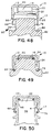
- FIGURES 48 to 50 are illustrative of how the curling operation of the invention can be combined with the curling operation described in US-A- 4 709 824 to concurrently form the linerless seal of the present invention and the breakaway ring of the invention of my copending application.
- the cap 10 is molded with a line of weakness 17 including bridges 66 and a depending tubular band 68 as well as with the preforms annular wall 18 depending from the lid 12 for an internal integral or linerless seal 16.
- the wall 18 includes an upper end 20 integral with the lid 12 and a depending free end 22.
- the curling tool 80 has an upper portion 26 with an annular groove 28 for forming an inward curl in the free end 22 and a lower portion 82 having an annular groove 84 for forming an inward curl in the free end 72.
- the tool upper portion 26 is positioned within the annular groove 84, extends upwardly, and has a diameter which is less than the diameter of the cap 10 so that it can extend thereinto to form the linerless seal 16.
- FIGURE 48 the tool 80 is positioned below and within the cap 10 ready to engage simultaneously the outer and inner tubular walls 68 and 18.
- Figure 49 shows the curling tool 80 fully engaged with cap 10 having completed the formation of an "O" ring curl 24 to produce linerless seal 16 and a breakaway ring 76.
- the wall 68 is curled to a lesser extent than for the "O" ring curl 24 of the linerless seal 16 by stopping the curling compression at the appropriate stage. This results in a "J" shape for the ring 76 which engages locking ring 41 of bottle neck 38 as shown by FIGURE 50.
- the linerless "O" ring seal 16 is a plug seal which engages and seals against the wall 46 of the bottle opening 42 in the neck 38 thereof.
Landscapes
- Engineering & Computer Science (AREA)
- Mechanical Engineering (AREA)
- Closures For Containers (AREA)
- Shaping Of Tube Ends By Bending Or Straightening (AREA)
- Making Paper Articles (AREA)
- Sealing Battery Cases Or Jackets (AREA)
Claims (16)
- Procédé de formation d'un bouchon ayant un joint de matière plastique sans revêtement, comprenant :
la formation d'un bouchon ayant une paroi supérieure qui comprend une partie ayant une surface destinée à former un joint d'étanchéité sans revêtement à l'intérieur du bouchon et qui est formé d'une matière plastique choisie dans le groupe constitué des polymères qui, lorsqu'ils sont étirés, créent des vides microscopiques qui assouplissent la matière plastique et accroissent sa compressibilité, et
la mise en contact de la partie du bouchon avec un outil destiné à provoquer un étirage préalable de la surface de ladite partie sous forme d'un joint d'étanchéité de matière plastique sans revêtement à l'intérieur du bouchon, ce joint étant plus souple que les parties contiguës non étirées et, lorsqu'il est mis en contact, formant une surface d'étanchéité sans revêtement, ayant subi un étirage préalable et un assouplissement préalable dans la partie destinée à assurer la compression et l'étanchéité. - Procédé selon la revendication 1, dans lequel le joint d'étanchéité de matière plastique sans revêtement est étiré avec une configuration en coupe choisie dans le groupe comprenant un enroulement, un O, un U, un J ou un quart de cercle.
- Procédé selon la revendication 1 ou 2, dans lequel le joint d'étanchéité de matière plastique sans revêtement est étiré de manière que sa surface assouplie d'étanchéité soit sous tension.
- Bouchon formé par le procédé selon l'une quelconque des revendications précédentes.
- Bouchon destiné à un récipient, comprenant :
une paroi supérieure et une paroi dépassant sous la paroi supérieure à l'intérieur du bouchon, formée de matière plastique et ayant une partie possédant une surface d'étanchéité, la matière plastique étant choisie dans le groupe constitué des polymères qui, lorsqu'ils sont étirés, forment des vides microscopiques qui assouplissent la matière plastique et la rendent plus compressible, la matière plastique étant préalablement étirée afin que la surface d'étanchéité sans revêtement, ayant subi un étirage préalable et préalablement assouplie, comporte des pores microscopiques, la surface, lorsqu'elle est au contact du récipient, étant destinée à assurer une compression et une étanchéité. - Bouchon selon la revendication 5, dans lequel la surface d'étanchéité ayant subi un étirage préalable a une configuration en coupe choisie dans le groupe qui comprend un enroulement, un O, un U, un J ou un quart de cercle.
- Bouchon selon la revendication 5 ou 6, dans lequel la surface d'étanchéité a subi un étirage préalable de manière que sa surface souple d'étanchéité soit sous tension.
- Bouchon selon l'une quelconque des revendications 5 à 7, dans lequel la paroi supérieure du bouchon a une gorge distante latéralement de la paroi descendante au niveau de la partie supérieure pour le logement de la surface d'étanchéité.
- Bouchon selon l'une quelconque des revendications 5 à 8, dans lequel la surface d'étanchéité est recourbée vers l'intérieur.
- Bouchon selon l'une quelconque des revendications 5 à 8, dans lequel la surface d'étanchéité est recourbée vers l'extérieur.
- Bouchon selon l'une quelconque des revendications 5 à 10, sous forme d'un bouchon à visser.
- Bouchon selon l'une quelconque des revendications 5 à 10, qui est sous forme d'un bouchon à enclenchement élastique.
- Bouchon selonl'une quelconque des revendications 5 à 10, dans lequel la surface d'étanchéité est formée par un joint d'étanchéité à emmancher intérieurement, à appliquer par-dessus ou de coin.
- Bouchon selon l'une quelconque des revendications 5 à 13, combiné à un récipient.
- Combinaison selon la revendication 14, dans laquelle le récipient est formé de verre.
- Combinaison selon la revendication 14, dans laquelle le récipient est formé d'une matière plastique.
Applications Claiming Priority (3)
| Application Number | Priority Date | Filing Date | Title |
|---|---|---|---|
| US61304 | 1987-06-10 | ||
| US07/061,304 US4872304A (en) | 1985-12-12 | 1987-06-10 | Closure cap with a seal and method of and apparatus for forming such closure and seal |
| PCT/US1988/001967 WO1988009722A1 (fr) | 1987-06-10 | 1988-06-09 | Couvercle de fermeture avec joint d'etancheite et procede et appareil de formation de ce joint de fermeture hermetique |
Publications (2)
| Publication Number | Publication Date |
|---|---|
| EP0365592A1 EP0365592A1 (fr) | 1990-05-02 |
| EP0365592B1 true EP0365592B1 (fr) | 1995-11-08 |
Family
ID=22034930
Family Applications (1)
| Application Number | Title | Priority Date | Filing Date |
|---|---|---|---|
| EP88906358A Expired - Lifetime EP0365592B1 (fr) | 1987-06-10 | 1988-06-09 | Couvercle de fermeture avec joint d'etancheite et procede de formation de ce joint |
Country Status (8)
| Country | Link |
|---|---|
| US (1) | US4872304A (fr) |
| EP (1) | EP0365592B1 (fr) |
| JP (1) | JP2836831B2 (fr) |
| AT (1) | ATE129958T1 (fr) |
| AU (3) | AU625493B2 (fr) |
| CA (1) | CA1338265C (fr) |
| DE (1) | DE3854669T2 (fr) |
| WO (1) | WO1988009722A1 (fr) |
Families Citing this family (28)
| Publication number | Priority date | Publication date | Assignee | Title |
|---|---|---|---|---|
| US4975132A (en) * | 1987-10-30 | 1990-12-04 | Tri-Tech Systems International, Inc. | Plastic closures for containers and cans and methods and apparatus for producing such closures |
| FR2631934B1 (fr) * | 1988-05-30 | 1990-12-14 | Astra Plastique | Dispositif de bouchage comprenant un bouchon et une bague d'inviolabilite, et procede pour sa fabrication |
| US5638972A (en) * | 1988-06-17 | 1997-06-17 | Druitt; Rodney Malcolm | Linerless closure for carbonated beverage container |
| KR960013293B1 (ko) * | 1988-06-17 | 1996-10-02 | 로드니 말콤 드루이트 | 탄산음료수 용기를 위한 라이너없는 밀폐체 |
| US5348182A (en) * | 1991-03-05 | 1994-09-20 | Portola Packaging, Inc. | Means for attaching fitment and method of applying fitment |
| USRE36729E (en) * | 1991-08-07 | 2000-06-13 | Portola Packaging, Inc. | Container with curled tamper-evident band to retain closure |
| US5163575A (en) * | 1991-08-07 | 1992-11-17 | Cup Snap Co. | Container with curled tamper-evident band to retain closure |
| US5398836A (en) * | 1993-03-23 | 1995-03-21 | Portola Packaging, Inc. | Container with tamper-evident band having inward bent retainer projection to retain a lid and method of bending said projection |
| US5320236A (en) * | 1992-04-27 | 1994-06-14 | Owens-Illinois Closure Inc. | Plastic container package with linerless sealing closure system |
| US5980230A (en) * | 1997-04-11 | 1999-11-09 | Velcro Industries B.V. | Forming fastener products |
| AUPO788597A0 (en) | 1997-07-14 | 1997-08-07 | Closures And Packaging Services Limited | Closure |
| US6102225A (en) * | 1998-03-06 | 2000-08-15 | Ball Corporation | Container with internally threaded finish and seal |
| US6685049B1 (en) * | 1999-11-19 | 2004-02-03 | Landis Plastics, Inc. | Thin wall closure for use with a container |
| US6602309B2 (en) * | 2000-05-26 | 2003-08-05 | Performance Systematix, Inc. | Vented, grooved back, heat induction foil |
| US20050067367A1 (en) * | 2003-09-29 | 2005-03-31 | Fabricas Monterrey, S.A. De C.V. | Linerless metallic cap closure and method of fabricating the same |
| FR2882731B1 (fr) * | 2005-03-03 | 2007-05-18 | Bericap Sarl | Bouchon avec fonction anti-sabotage et securite au degazage |
| US20070110842A1 (en) * | 2005-11-15 | 2007-05-17 | Husky Injection Molding Systems Ltd. | System for molding and assembly of sterilized articles |
| US9156669B2 (en) * | 2009-06-26 | 2015-10-13 | Sidel S.P.A. | Liquid bottling method and machine, in particular for carbonated liquids or oxygen sensitive liquids |
| US8313123B1 (en) | 2009-08-05 | 2012-11-20 | Hinkle Derek H | Device for capping and sealing refrigeration service valve fittings of quick disconnect type |
| AU2011314333B2 (en) * | 2010-10-14 | 2016-01-07 | Medivators, Inc. | A universal cap |
| US10100273B2 (en) | 2010-11-22 | 2018-10-16 | Corning Incorporated | Closure assembly for cell culture apparatus |
| FR2991186B1 (fr) * | 2012-05-31 | 2015-05-15 | Valois Sas | Dispositif de distribution de produit fluide. |
| US9424722B2 (en) * | 2014-05-14 | 2016-08-23 | Unlimited Liability, LLC | Smart memory material lock devices |
| WO2015193971A1 (fr) * | 2014-06-17 | 2015-12-23 | サントリーホールディングス株式会社 | Capuchon en résine |
| WO2016176672A1 (fr) * | 2015-04-30 | 2016-11-03 | Berry Plastics Corporation | Fermeture de récipient |
| CN108137201B (zh) * | 2015-10-23 | 2020-12-01 | 赫斯基注塑系统有限公司 | 容器和封闭物 |
| DE102018205581A1 (de) * | 2018-04-12 | 2019-10-17 | Henkel Ag & Co. Kgaa | Verschlusskappe für Waschmittelflasche |
| US12606351B2 (en) | 2019-12-12 | 2026-04-21 | Plastipak Packaging, Inc. | Tethered closure and container assembly |
Family Cites Families (102)
| Publication number | Priority date | Publication date | Assignee | Title |
|---|---|---|---|---|
| US521788A (en) * | 1894-06-26 | Robert flanigan | ||
| US809057A (en) * | 1905-06-15 | 1906-01-02 | James K Hester | Attachment for ladders. |
| US809058A (en) * | 1905-06-24 | 1906-01-02 | Titus Hinaman | Mail-pouch fastener. |
| US953513A (en) * | 1906-03-05 | 1910-03-29 | Edwin R Cahoone | Stove. |
| FR555488A (fr) * | 1921-08-31 | 1923-06-30 | Perfectionnements aux garnitures pour joint | |
| US1770548A (en) * | 1926-10-04 | 1930-07-15 | Victor Mfg & Gasket Co | Gasket |
| US2340353A (en) * | 1940-01-03 | 1944-02-01 | Marvin S Weaver | Bottle |
| US2423957A (en) * | 1942-09-14 | 1947-07-15 | Chicago Pneumatic Tool Co | Driver for clinch nuts and the like |
| US2456560A (en) * | 1944-02-14 | 1948-12-14 | Milton M Weinstein | Receptacle closure means |
| US2385105A (en) * | 1944-04-12 | 1945-09-18 | Deming Co | Pump |
| US2447340A (en) * | 1944-06-14 | 1948-08-17 | Case Co J I | Packed joint for cylinder barrels |
| CH253764A (de) * | 1947-04-03 | 1948-03-31 | United Shoe Machinery Corp Fle | Verfahren zum Verformen von Formstücken. |
| DE1043847B (de) * | 1955-09-22 | 1958-11-13 | Karl Huber Blechwarenfabrik | Verschlussmittel fuer Flaschen, Glaeser od. dgl. |
| GB788148A (en) * | 1956-08-03 | 1957-12-23 | Metal Box Co Ltd | Improvements in or relating to closures for containers |
| US2852054A (en) * | 1956-11-23 | 1958-09-16 | Motley Murat Brunson | Container and closure therefor |
| CH351515A (de) * | 1957-02-18 | 1961-01-15 | Huber Karl Blechwarenfabrik | Verschlussmittel an einem unter Überdruck stehenden Behälter, wie einer Flasche oder einem Glas |
| US2933786A (en) * | 1957-05-13 | 1960-04-26 | Edwin F Peterson | Blow tube for core blowing machines |
| US2961119A (en) * | 1957-11-25 | 1960-11-22 | Charles F Leach | Closure devices |
| US3065677A (en) * | 1959-07-20 | 1962-11-27 | Paper Machinery Corp | Rim curling mechanism for containers |
| GB930866A (en) * | 1961-01-06 | 1963-07-10 | Ashlin Hodson | Improvements in or relating to closures for bottles and other containers |
| US3200981A (en) * | 1961-10-03 | 1965-08-17 | Wicanders Korkfabriker Ab | Bottle caps |
| US3405439A (en) * | 1962-12-18 | 1968-10-15 | Hokkai Can | Method of making synthetic resin receptacles |
| US3171458A (en) * | 1963-08-06 | 1965-03-02 | Strong Plastics Inc | Plastic container |
| DE1432178A1 (de) * | 1963-11-07 | 1968-12-19 | Walter Heubl | Flaschenverschluss aus Kunststoff |
| US3243851A (en) * | 1964-02-21 | 1966-04-05 | Jr Erwin Reitter | Die for making plastic container closures |
| US3250417A (en) * | 1964-02-21 | 1966-05-10 | Du Pont | Plastic container closures |
| GB1048727A (en) * | 1964-04-14 | 1966-11-16 | Metal Box Co Ltd | Improvements in or relating to the formation of curled edges or lips on thermoplastic articles |
| US3272369A (en) * | 1964-10-07 | 1966-09-13 | American Can Co | Container closure |
| GB1104001A (en) * | 1964-12-09 | 1968-02-21 | Eugene Joseph Treanor | Closures for containers |
| US3286866A (en) * | 1965-04-15 | 1966-11-22 | Mack Wayne Plastics Co | Plastic cap |
| US3352127A (en) * | 1965-06-17 | 1967-11-14 | Renniks Corp | Seals |
| US3339770A (en) * | 1965-07-12 | 1967-09-05 | Tamper Proof Tops Ind Ltd | Container closure |
| US3285452A (en) * | 1965-09-27 | 1966-11-15 | Continental Can Co | Container finish and closure cap construction |
| US3374913A (en) * | 1965-10-08 | 1968-03-26 | Continental Can Co | Tamper-proof package |
| US3418409A (en) * | 1965-10-15 | 1968-12-24 | Johns Manville | Method for thickening the end of plastic pipe |
| US3352448A (en) * | 1965-11-15 | 1967-11-14 | Jay G Livingstone | Resilient closure |
| US3344942A (en) * | 1966-04-05 | 1967-10-03 | Hedgewick Peter | Safety cap and container |
| US3482725A (en) * | 1966-12-06 | 1969-12-09 | Klm Co | Closures and methods of making the same |
| US3460703A (en) * | 1967-07-18 | 1969-08-12 | Aluminum Co Of America | Container and closure |
| US3532786A (en) * | 1967-12-14 | 1970-10-06 | Shell Oil Co | Solid state forming of plastics |
| US3567233A (en) * | 1968-07-11 | 1971-03-02 | Fred C Stepanich | Gasket means for pipe |
| US3557275A (en) * | 1968-07-22 | 1971-01-19 | Pacific Western Extruded Produ | Method for cold forming beaded plastic tubing |
| US3714320A (en) * | 1968-09-30 | 1973-01-30 | Shell Oil Co | Cold extrusion process |
| GB1302201A (fr) * | 1969-01-07 | 1973-01-04 | ||
| US3557985A (en) * | 1969-06-02 | 1971-01-26 | Marcel Louis St Denis | Tamper-proof plastic closure cap and method of making same |
| US3612324A (en) * | 1969-09-25 | 1971-10-12 | Dell M Malick | Safety cap and container neck construction |
| IL36264A (en) * | 1970-03-17 | 1975-02-10 | Sanders B | Method of providing holes in a sheet of synthetic resinous material |
| US3861551A (en) * | 1971-02-22 | 1975-01-21 | Charles N Hannon | Threaded bottle cap with vertical external scores |
| US3784041A (en) * | 1971-05-05 | 1974-01-08 | R Birch | Closure cap |
| US3820799A (en) * | 1972-08-16 | 1974-06-28 | Commissariat Energie Atomique | Resilient metal gasket |
| DE2340647A1 (de) * | 1973-08-10 | 1975-02-20 | Obrist Ag Albert | Verschlusskappe |
| US4153172A (en) * | 1973-08-13 | 1979-05-08 | Walter Bialobrzeski | Container safety closure |
| GB1489287A (en) * | 1974-09-16 | 1977-10-19 | Mack Wayne Plastics Co | Linerless cap and container combination |
| CH583647A5 (fr) * | 1975-04-04 | 1977-01-14 | Obrist Ag Albert | |
| DE2529340C3 (de) * | 1975-07-01 | 1980-08-28 | Albert Obrist Ag, Reinach, Basel (Schweiz) | Behälter mit einer Schraubkappe und Verfahren zum Aufsetzen der Schraubkappe |
| NL181793C (nl) * | 1975-07-01 | 1987-11-02 | Obrist Ag Crown | Houder met een schroefkap. |
| CH607702A5 (en) * | 1975-08-18 | 1978-10-13 | Obrist Ag Albert | Bottle closure, in particular a screw closure, and process for fastening the closure |
| FR2391926A2 (fr) * | 1976-02-03 | 1978-12-22 | Grussen Jean | Capsule de bouchage a vis a etancheite amelioree et moule de fabrication |
| US4091948A (en) * | 1976-03-15 | 1978-05-30 | Northup John D | Linerless container closure |
| US4069937A (en) * | 1977-01-28 | 1978-01-24 | Owens-Illinois, Inc. | Linerless closure |
| FR2391117A2 (fr) * | 1977-05-20 | 1978-12-15 | Grussen Jean | Capsule de bouchage a vis a etancheite amelioree et moule de fabrication |
| US4209102A (en) * | 1977-07-18 | 1980-06-24 | Aluminum Company Of America | Linerless plastic closure |
| US4141463A (en) * | 1977-12-08 | 1979-02-27 | Phillips Petroleum Company | Hermetically sealed container |
| AU516094B2 (en) * | 1977-12-14 | 1981-05-14 | Metal Closures Group Limited | Closures for containers |
| GB1591694A (en) * | 1978-02-01 | 1981-06-24 | Metal Box Co Ltd | Containers and closures therefor |
| US4143785A (en) * | 1978-03-16 | 1979-03-13 | Sun Coast Plastic Closures, Inc. | Plastic vacuum sealing cap |
| CH626693A5 (fr) * | 1978-03-30 | 1981-11-30 | Balzers Hochvakuum | |
| DE2829755A1 (de) * | 1978-07-06 | 1980-01-17 | Crown Cork Belgium | Verfahren zum gasdichten verschliessen eines behaelters und verschlusskappe fuer dieses verfahren |
| EP0012713B1 (fr) * | 1978-10-20 | 1983-04-27 | GRETAG Aktiengesellschaft | Procédé de commande de l'exposition pour la réalisation de reproductions photographiques |
| US4206852A (en) * | 1979-01-26 | 1980-06-10 | Aluminum Company Of America | Linerless closure for pressurized container |
| US4218067A (en) * | 1979-02-02 | 1980-08-19 | Pressure Science Incorporated | Multi-ply sealing rings |
| US4257525A (en) * | 1979-04-10 | 1981-03-24 | Thompson Mortimer S | Bottle with attached handle |
| US4497765A (en) * | 1979-09-21 | 1985-02-05 | H-C Industries, Inc. | Process for making a closure |
| US4281979A (en) * | 1979-10-26 | 1981-08-04 | Owens-Illinois, Inc. | Apparatus to form a flat-topped rim on a thin-walled foam plastic container |
| US4386044A (en) * | 1979-11-09 | 1983-05-31 | Owens-Illinois, Inc. | Method of forming a cup-like container |
| GR72763B (fr) * | 1980-02-14 | 1983-12-02 | Obrist Ag Albert | |
| US4274544A (en) * | 1980-03-11 | 1981-06-23 | The Continental Group, Inc. | Single-piece plastic closure having integral seal forming means |
| US4281774A (en) * | 1980-03-17 | 1981-08-04 | Owens-Illinois, Inc. | Tamper proof snap cap |
| US4343408A (en) * | 1980-04-21 | 1982-08-10 | General Kap (P.R.) Corporation | Tamper-evident plastic closure |
| DE3038453A1 (de) * | 1980-10-11 | 1982-05-27 | Stella KG Werner Deussen, 6228 Eltville | Schraubverschluss mit originalitaetssicherung |
| US4360149A (en) * | 1980-11-10 | 1982-11-23 | Hein Jr George N | Centrifuge rotor with liquid supported swinging tubes |
| FR2499519A1 (fr) * | 1981-02-11 | 1982-08-13 | Grussen Jean | Capsule de bouchage a vis avec anneau d'inviolabilite |
| US4418828A (en) * | 1981-07-24 | 1983-12-06 | H-C Industries, Inc. | Plastic closure with mechanical pilfer band |
| US4392579A (en) * | 1981-10-21 | 1983-07-12 | Owens-Illinois, Inc. | Closure with domed portion |
| US4360114A (en) * | 1981-11-16 | 1982-11-23 | Thoroughbred Plastics Corp. | Linerless bottle cap |
| US4475274A (en) * | 1982-07-07 | 1984-10-09 | Hunt-Wesson Foods, Inc. | Method of making and installing a pouring fitment |
| US4470513A (en) * | 1982-09-23 | 1984-09-11 | Ethyl Molded Products Company | Tamper-indicating closure |
| US4442947A (en) * | 1983-01-18 | 1984-04-17 | Continental White Cap, Inc. | Plastic closure with sealing flaps |
| US4595547A (en) * | 1983-02-18 | 1986-06-17 | Kerr Glass Manufacturing Corporation | Method of manufacturing a tamper evident closure |
| US4506795A (en) * | 1983-02-18 | 1985-03-26 | Kerr Glass Manufacturing Corporation | Tamper-evident closure |
| CA1184727A (fr) * | 1983-04-27 | 1985-04-02 | Paul E. Kaspe | Methode et dispositif de faconnage d'une bride faisant corps avec l'extremite d'un tuyau souple |
| US4563325A (en) * | 1983-05-20 | 1986-01-07 | Shell Oil Company | Forming plastic articles in solid state |
| US4546029A (en) * | 1984-06-18 | 1985-10-08 | Clopay Corporation | Random embossed matte plastic film |
| US4550844A (en) * | 1984-06-22 | 1985-11-05 | Owens-Illinois, Inc. | Tamper resistant closure with tear-off band |
| US4552279A (en) * | 1984-09-14 | 1985-11-12 | Owens-Illinois, Inc. | Container closure |
| DE3523771A1 (de) * | 1985-07-03 | 1987-01-08 | Albert Stewing | Verfahren und spritzgussmaschine zum herstellen von waermeschrumpfmanschetten aus thermoplastischem kunststoff |
| JPS62134033A (ja) * | 1985-12-09 | 1987-06-17 | 株式会社 中嶋製作所 | 卵の移送装置 |
| US4709824A (en) * | 1985-12-12 | 1987-12-01 | Tri-Tech Systems International Inc. | Tamper evident plastic caps with lower separable or breakaway portions and a method of forming them |
| US4708255A (en) * | 1985-12-12 | 1987-11-24 | Tri-Tech Systems International Inc. | Closure cap with a linerless seal and a method for forming such closure and seal |
| US4770309A (en) * | 1987-06-10 | 1988-09-13 | Tri-Tech Systems International, Inc. | Closure cap with a linerless seal and method of forming such closure and seal |
| US4793506A (en) * | 1987-06-10 | 1988-12-27 | Tri-Tech Systems International Inc. | Closure cap with a seal and method of and apparatus for forming such closure and seal |
| US4811857A (en) * | 1987-06-17 | 1989-03-14 | Tri-Tech Systems International Inc. | Closure system and method of forming and using same |
-
1987
- 1987-06-10 US US07/061,304 patent/US4872304A/en not_active Expired - Lifetime
-
1988
- 1988-06-09 DE DE3854669T patent/DE3854669T2/de not_active Expired - Fee Related
- 1988-06-09 AU AU19673/88A patent/AU625493B2/en not_active Ceased
- 1988-06-09 EP EP88906358A patent/EP0365592B1/fr not_active Expired - Lifetime
- 1988-06-09 JP JP63505628A patent/JP2836831B2/ja not_active Expired - Lifetime
- 1988-06-09 AT AT88906358T patent/ATE129958T1/de not_active IP Right Cessation
- 1988-06-09 WO PCT/US1988/001967 patent/WO1988009722A1/fr not_active Ceased
- 1988-06-09 CA CA000569103A patent/CA1338265C/fr not_active Expired - Fee Related
-
1992
- 1992-10-15 AU AU27050/92A patent/AU662172B2/en not_active Ceased
-
1995
- 1995-10-25 AU AU34446/95A patent/AU687633B2/en not_active Ceased
Also Published As
| Publication number | Publication date |
|---|---|
| AU687633B2 (en) | 1998-02-26 |
| AU2705092A (en) | 1992-12-17 |
| DE3854669T2 (de) | 1996-07-11 |
| EP0365592A1 (fr) | 1990-05-02 |
| JP2836831B2 (ja) | 1998-12-14 |
| JPH03500625A (ja) | 1991-02-14 |
| ATE129958T1 (de) | 1995-11-15 |
| US4872304A (en) | 1989-10-10 |
| CA1338265C (fr) | 1996-04-23 |
| AU625493B2 (en) | 1992-07-16 |
| WO1988009722A1 (fr) | 1988-12-15 |
| AU662172B2 (en) | 1995-08-24 |
| DE3854669D1 (de) | 1995-12-14 |
| AU3444695A (en) | 1995-12-14 |
Similar Documents
| Publication | Publication Date | Title |
|---|---|---|
| EP0365592B1 (fr) | Couvercle de fermeture avec joint d'etancheite et procede de formation de ce joint | |
| US4708255A (en) | Closure cap with a linerless seal and a method for forming such closure and seal | |
| JP2994395B2 (ja) | 捩りキャップおよびその形成方法ならびに容器−キャップ組合せ | |
| US4628669A (en) | Method of applying roll-on closures | |
| EP1799573B1 (fr) | Fermeture | |
| US5100009A (en) | Closure and access systems for containers and methods of manufacture and use | |
| US4813557A (en) | Pasteurizable container closure | |
| US3247994A (en) | Plastic caps for use as closure for containers | |
| US4793506A (en) | Closure cap with a seal and method of and apparatus for forming such closure and seal | |
| US4770309A (en) | Closure cap with a linerless seal and method of forming such closure and seal | |
| US5158195A (en) | Closure cap with a seal and method of and apparatus for forming such closure and seal | |
| MXPA05001263A (es) | Cierre de energia de aplicacion reducida. | |
| US4925617A (en) | Method of forming a closure cap with a seal | |
| EP0154502B1 (fr) | Fermeture pour récipient destiné à être pasteurisé | |
| JPH0755714B2 (ja) | 開封検知部付プラスチック封止栓 | |
| NO873344L (no) | Kapselforsegling, fremgangsmaate og apparat for fremstilling derav. | |
| HK1101817B (en) | Closure |
Legal Events
| Date | Code | Title | Description |
|---|---|---|---|
| PUAI | Public reference made under article 153(3) epc to a published international application that has entered the european phase |
Free format text: ORIGINAL CODE: 0009012 |
|
| 17P | Request for examination filed |
Effective date: 19891208 |
|
| AK | Designated contracting states |
Kind code of ref document: A1 Designated state(s): AT BE CH DE FR GB IT LI LU NL SE |
|
| 17Q | First examination report despatched |
Effective date: 19910604 |
|
| RAP1 | Party data changed (applicant data changed or rights of an application transferred) |
Owner name: INNOVATIVE CLOSURES, INC. |
|
| GRAA | (expected) grant |
Free format text: ORIGINAL CODE: 0009210 |
|
| AK | Designated contracting states |
Kind code of ref document: B1 Designated state(s): AT BE CH DE FR GB IT LI LU NL SE |
|
| REF | Corresponds to: |
Ref document number: 129958 Country of ref document: AT Date of ref document: 19951115 Kind code of ref document: T |
|
| REF | Corresponds to: |
Ref document number: 3854669 Country of ref document: DE Date of ref document: 19951214 |
|
| ET | Fr: translation filed | ||
| ITF | It: translation for a ep patent filed | ||
| REG | Reference to a national code |
Ref country code: CH Ref legal event code: NV Representative=s name: SCHAAD, BALASS & PARTNER AG |
|
| RAP2 | Party data changed (patent owner data changed or rights of a patent transferred) |
Owner name: ZAPATA INNOVATIVE CLOSURES, INC. |
|
| NLT2 | Nl: modifications (of names), taken from the european patent patent bulletin |
Owner name: ZAPATA INNOVATIVE CLOSURES, INC. |
|
| PGFP | Annual fee paid to national office [announced via postgrant information from national office to epo] |
Ref country code: SE Payment date: 19960620 Year of fee payment: 9 |
|
| PGFP | Annual fee paid to national office [announced via postgrant information from national office to epo] |
Ref country code: BE Payment date: 19960621 Year of fee payment: 9 Ref country code: AT Payment date: 19960621 Year of fee payment: 9 |
|
| PGFP | Annual fee paid to national office [announced via postgrant information from national office to epo] |
Ref country code: NL Payment date: 19960630 Year of fee payment: 9 |
|
| PGFP | Annual fee paid to national office [announced via postgrant information from national office to epo] |
Ref country code: LU Payment date: 19960701 Year of fee payment: 9 |
|
| REG | Reference to a national code |
Ref country code: CH Ref legal event code: PUE Owner name: INNOVATIVE CLOSURES, INC. TRANSFER- ZAPATA INNOVAT |
|
| PLBE | No opposition filed within time limit |
Free format text: ORIGINAL CODE: 0009261 |
|
| STAA | Information on the status of an ep patent application or granted ep patent |
Free format text: STATUS: NO OPPOSITION FILED WITHIN TIME LIMIT |
|
| 26N | No opposition filed | ||
| NLT1 | Nl: modifications of names registered in virtue of documents presented to the patent office pursuant to art. 16 a, paragraph 1 |
Owner name: ZAPATA INNOVATIVE CLOSURES, INC. |
|
| REG | Reference to a national code |
Ref country code: FR Ref legal event code: CD Ref country code: FR Ref legal event code: CA |
|
| PG25 | Lapsed in a contracting state [announced via postgrant information from national office to epo] |
Ref country code: LU Free format text: LAPSE BECAUSE OF NON-PAYMENT OF DUE FEES Effective date: 19970609 Ref country code: AT Effective date: 19970609 |
|
| PG25 | Lapsed in a contracting state [announced via postgrant information from national office to epo] |
Ref country code: SE Effective date: 19970610 |
|
| PG25 | Lapsed in a contracting state [announced via postgrant information from national office to epo] |
Ref country code: BE Effective date: 19970630 |
|
| BERE | Be: lapsed |
Owner name: ZAPATA INNOVATIVE CLOSURES INC. Effective date: 19970630 |
|
| PG25 | Lapsed in a contracting state [announced via postgrant information from national office to epo] |
Ref country code: NL Effective date: 19980101 |
|
| EUG | Se: european patent has lapsed |
Ref document number: 88906358.2 |
|
| NLV4 | Nl: lapsed or anulled due to non-payment of the annual fee |
Effective date: 19980101 |
|
| REG | Reference to a national code |
Ref country code: GB Ref legal event code: IF02 |
|
| PGFP | Annual fee paid to national office [announced via postgrant information from national office to epo] |
Ref country code: GB Payment date: 20020523 Year of fee payment: 15 |
|
| PGFP | Annual fee paid to national office [announced via postgrant information from national office to epo] |
Ref country code: FR Payment date: 20020617 Year of fee payment: 15 |
|
| PGFP | Annual fee paid to national office [announced via postgrant information from national office to epo] |
Ref country code: CH Payment date: 20020621 Year of fee payment: 15 |
|
| PGFP | Annual fee paid to national office [announced via postgrant information from national office to epo] |
Ref country code: DE Payment date: 20020628 Year of fee payment: 15 |
|
| PG25 | Lapsed in a contracting state [announced via postgrant information from national office to epo] |
Ref country code: GB Free format text: LAPSE BECAUSE OF NON-PAYMENT OF DUE FEES Effective date: 20030609 |
|
| PG25 | Lapsed in a contracting state [announced via postgrant information from national office to epo] |
Ref country code: LI Free format text: LAPSE BECAUSE OF NON-PAYMENT OF DUE FEES Effective date: 20030630 Ref country code: CH Free format text: LAPSE BECAUSE OF NON-PAYMENT OF DUE FEES Effective date: 20030630 |
|
| PG25 | Lapsed in a contracting state [announced via postgrant information from national office to epo] |
Ref country code: DE Free format text: LAPSE BECAUSE OF NON-PAYMENT OF DUE FEES Effective date: 20040101 |
|
| GBPC | Gb: european patent ceased through non-payment of renewal fee |
Effective date: 20030609 |
|
| REG | Reference to a national code |
Ref country code: CH Ref legal event code: PL |
|
| PG25 | Lapsed in a contracting state [announced via postgrant information from national office to epo] |
Ref country code: FR Free format text: LAPSE BECAUSE OF NON-PAYMENT OF DUE FEES Effective date: 20040227 |
|
| REG | Reference to a national code |
Ref country code: FR Ref legal event code: ST |
|
| PG25 | Lapsed in a contracting state [announced via postgrant information from national office to epo] |
Ref country code: IT Free format text: LAPSE BECAUSE OF NON-PAYMENT OF DUE FEES;WARNING: LAPSES OF ITALIAN PATENTS WITH EFFECTIVE DATE BEFORE 2007 MAY HAVE OCCURRED AT ANY TIME BEFORE 2007. THE CORRECT EFFECTIVE DATE MAY BE DIFFERENT FROM THE ONE RECORDED. Effective date: 20050609 |