EP0365634B1 - Procede et appareil pour encodage consistant a former un mot code par combinaison d'une premiere sequence de code avec une seconde sequence de code - Google Patents
Procede et appareil pour encodage consistant a former un mot code par combinaison d'une premiere sequence de code avec une seconde sequence de code Download PDFInfo
- Publication number
- EP0365634B1 EP0365634B1 EP19890904394 EP89904394A EP0365634B1 EP 0365634 B1 EP0365634 B1 EP 0365634B1 EP 19890904394 EP19890904394 EP 19890904394 EP 89904394 A EP89904394 A EP 89904394A EP 0365634 B1 EP0365634 B1 EP 0365634B1
- Authority
- EP
- European Patent Office
- Prior art keywords
- code
- codeword
- sector
- preliminary
- sequence
- Prior art date
- Legal status (The legal status is an assumption and is not a legal conclusion. Google has not performed a legal analysis and makes no representation as to the accuracy of the status listed.)
- Expired - Lifetime
Links
- 238000000034 method Methods 0.000 title claims abstract description 36
- 230000009897 systematic effect Effects 0.000 claims abstract description 7
- 125000004122 cyclic group Chemical group 0.000 claims description 5
- 238000011156 evaluation Methods 0.000 claims 2
- 239000012634 fragment Substances 0.000 claims 2
- 238000010586 diagram Methods 0.000 description 9
- 238000013459 approach Methods 0.000 description 2
- 238000004519 manufacturing process Methods 0.000 description 2
- 239000002131 composite material Substances 0.000 description 1
- 230000007547 defect Effects 0.000 description 1
- 230000000694 effects Effects 0.000 description 1
Images




Classifications
-
- H—ELECTRICITY
- H03—ELECTRONIC CIRCUITRY
- H03M—CODING; DECODING; CODE CONVERSION IN GENERAL
- H03M13/00—Coding, decoding or code conversion, for error detection or error correction; Coding theory basic assumptions; Coding bounds; Error probability evaluation methods; Channel models; Simulation or testing of codes
- H03M13/03—Error detection or forward error correction by redundancy in data representation, i.e. code words containing more digits than the source words
- H03M13/05—Error detection or forward error correction by redundancy in data representation, i.e. code words containing more digits than the source words using block codes, i.e. a predetermined number of check bits joined to a predetermined number of information bits
- H03M13/13—Linear codes
- H03M13/15—Cyclic codes, i.e. cyclic shifts of codewords produce other codewords, e.g. codes defined by a generator polynomial, Bose-Chaudhuri-Hocquenghem [BCH] codes
- H03M13/151—Cyclic codes, i.e. cyclic shifts of codewords produce other codewords, e.g. codes defined by a generator polynomial, Bose-Chaudhuri-Hocquenghem [BCH] codes using error location or error correction polynomials
- H03M13/1515—Reed-Solomon codes
-
- G—PHYSICS
- G11—INFORMATION STORAGE
- G11B—INFORMATION STORAGE BASED ON RELATIVE MOVEMENT BETWEEN RECORD CARRIER AND TRANSDUCER
- G11B20/00—Signal processing not specific to the method of recording or reproducing; Circuits therefor
- G11B20/10—Digital recording or reproducing
- G11B20/18—Error detection or correction; Testing, e.g. of drop-outs
- G11B20/1806—Pulse code modulation systems for audio signals
- G11B20/1813—Pulse code modulation systems for audio signals by adding special bits or symbols to the coded information
-
- G—PHYSICS
- G11—INFORMATION STORAGE
- G11B—INFORMATION STORAGE BASED ON RELATIVE MOVEMENT BETWEEN RECORD CARRIER AND TRANSDUCER
- G11B20/00—Signal processing not specific to the method of recording or reproducing; Circuits therefor
- G11B20/10—Digital recording or reproducing
- G11B20/18—Error detection or correction; Testing, e.g. of drop-outs
- G11B20/1883—Methods for assignment of alternate areas for defective areas
-
- H—ELECTRICITY
- H03—ELECTRONIC CIRCUITRY
- H03M—CODING; DECODING; CODE CONVERSION IN GENERAL
- H03M13/00—Coding, decoding or code conversion, for error detection or error correction; Coding theory basic assumptions; Coding bounds; Error probability evaluation methods; Channel models; Simulation or testing of codes
- H03M13/29—Coding, decoding or code conversion, for error detection or error correction; Coding theory basic assumptions; Coding bounds; Error probability evaluation methods; Channel models; Simulation or testing of codes combining two or more codes or code structures, e.g. product codes, generalised product codes, concatenated codes, inner and outer codes
-
- H—ELECTRICITY
- H03—ELECTRONIC CIRCUITRY
- H03M—CODING; DECODING; CODE CONVERSION IN GENERAL
- H03M13/00—Coding, decoding or code conversion, for error detection or error correction; Coding theory basic assumptions; Coding bounds; Error probability evaluation methods; Channel models; Simulation or testing of codes
- H03M13/29—Coding, decoding or code conversion, for error detection or error correction; Coding theory basic assumptions; Coding bounds; Error probability evaluation methods; Channel models; Simulation or testing of codes combining two or more codes or code structures, e.g. product codes, generalised product codes, concatenated codes, inner and outer codes
- H03M13/2903—Methods and arrangements specifically for encoding, e.g. parallel encoding of a plurality of constituent codes
-
- H—ELECTRICITY
- H03—ELECTRONIC CIRCUITRY
- H03M—CODING; DECODING; CODE CONVERSION IN GENERAL
- H03M13/00—Coding, decoding or code conversion, for error detection or error correction; Coding theory basic assumptions; Coding bounds; Error probability evaluation methods; Channel models; Simulation or testing of codes
- H03M13/29—Coding, decoding or code conversion, for error detection or error correction; Coding theory basic assumptions; Coding bounds; Error probability evaluation methods; Channel models; Simulation or testing of codes combining two or more codes or code structures, e.g. product codes, generalised product codes, concatenated codes, inner and outer codes
- H03M13/2906—Coding, decoding or code conversion, for error detection or error correction; Coding theory basic assumptions; Coding bounds; Error probability evaluation methods; Channel models; Simulation or testing of codes combining two or more codes or code structures, e.g. product codes, generalised product codes, concatenated codes, inner and outer codes using block codes
-
- H—ELECTRICITY
- H03—ELECTRONIC CIRCUITRY
- H03M—CODING; DECODING; CODE CONVERSION IN GENERAL
- H03M13/00—Coding, decoding or code conversion, for error detection or error correction; Coding theory basic assumptions; Coding bounds; Error probability evaluation methods; Channel models; Simulation or testing of codes
- H03M13/29—Coding, decoding or code conversion, for error detection or error correction; Coding theory basic assumptions; Coding bounds; Error probability evaluation methods; Channel models; Simulation or testing of codes combining two or more codes or code structures, e.g. product codes, generalised product codes, concatenated codes, inner and outer codes
- H03M13/2906—Coding, decoding or code conversion, for error detection or error correction; Coding theory basic assumptions; Coding bounds; Error probability evaluation methods; Channel models; Simulation or testing of codes combining two or more codes or code structures, e.g. product codes, generalised product codes, concatenated codes, inner and outer codes using block codes
- H03M13/2927—Decoding strategies
-
- H—ELECTRICITY
- H03—ELECTRONIC CIRCUITRY
- H03M—CODING; DECODING; CODE CONVERSION IN GENERAL
- H03M13/00—Coding, decoding or code conversion, for error detection or error correction; Coding theory basic assumptions; Coding bounds; Error probability evaluation methods; Channel models; Simulation or testing of codes
- H03M13/37—Decoding methods or techniques, not specific to the particular type of coding provided for in groups H03M13/03 - H03M13/35
- H03M13/3738—Decoding methods or techniques, not specific to the particular type of coding provided for in groups H03M13/03 - H03M13/35 with judging correct decoding
-
- G—PHYSICS
- G11—INFORMATION STORAGE
- G11B—INFORMATION STORAGE BASED ON RELATIVE MOVEMENT BETWEEN RECORD CARRIER AND TRANSDUCER
- G11B2220/00—Record carriers by type
- G11B2220/20—Disc-shaped record carriers
Definitions
- This invention relates to method for encoding information and for locating, reading, and writing information stored on a disk.
- the stored header that identifies each sector may be encoded to reduce the effect of bit errors that occur in recording.
- the header typically includes an address that uniquely identifies the sector and may include additional information, such as a bad sector flag and a servo correction number. To locate a particular sector on a specified track of the disk and to read or write data in that sector, the header of each sector along that track must be read and analyzed quickly.
- the sector address on the disk is read and compared with the specified address of the desired sector in which data is to be read or written. If the addresses match, the data will be read from or written to the sector.
- a sector address read from the disk has errors, the sector may be mistakenly identified, causing the disk drive to incorrectly determine, for example, that the head is located over sector 100 when it is actually located over sector 101. As a result, the read or write operation that is to occur at sector 100 will be performed on the wrong sector. If a sector address contains several errors or the address is corrupted due to a medium defect or soft error in the disk, the sector address may be unreadable making the sector unusable.
- the sector addresses must be written on the disk in such a way that even with a number of errors in the address, it will neither be read as the address of a different sector nor be rendered unidentifiable.
- US-3638182 there is described an error-correcting arrangement in which transmitted codewords contain two kinds of data: an encoded version of a current value, and an encoded portion of a previously-transmitted value.
- a codeword When a codeword is received, if the number of errors exceeds a threshold value, the codeword is discarded, and the value is reconstructed from the portions which appear in subsequent codewords.
- US-4598403 there is described an "interleaving" scheme in which multiple codes are overlapped to create more error-resilient codewords. In both of these references, information relating to the validity of the codeword is not available with full decoding of the codeword.
- the invention features a method and an apparatus as defined in Claims 1 and 25, respectively. It is suitable for quickly locating sectors on a magnetic disk, finding bad sectors on the disk, and centering a head on a track of the disk.
- the address of each sector is encoded as a first preliminary code sequence in accordance with a first code.
- a second preliminary code sequence is generated from bad sector information and servo control information about the location of the center of the track, in accordance with a second code.
- a code word is formed based on combining the first and second preliminary code sequences, and the codeword is recorded in the sector during formatting of the disk. The codeword, possibly corrupted, is read from each sector of the track rotating under the head.
- the first preliminary code sequence is stripped from the possibly corrupted codeword to derive a test sequence comprising a possibly corrupted version of the second preliminary code sequence.
- the test sequence is decoded in accordance with the second code to determine the number of errors in the corrupted codeword.
- the number of errors are compared to a threshold T. If the number of errors is no greater than T, the sector is accepted as the one being sought. Note that the sector address does not even need to be fully decoded; the information about the number of errors relative to T is sufficient to determine whether or not the desired sector has been reached. If decoded bad sector information indicates a bad sector, no write operation will be performed in that sector.
- the servo control information is used to control the position of the head.
- Another application of the invention is encoding bad sector, servo correction, and sector address values for storage in a header associated with a sector of storage in a storage medium; the address value with leading zero symbols is encoded in accordance with a code of a first rate; the bad sector and servo correction values are encoded in a systematic code having a second rate; and the first and second preliminary code sequences are combined to generate a codeword of the first code such that the bad sector and servo correction values appear explicitly in the codeword but the sector address value does not appear explicitly in the codeword.
- Another application of the invention encodes information in a codeword that may be subjected to no more than a predetermined degree of corruption, and then, without fully decoding a corrupted version of the codeword, determines from the corrupted codeword whether the information was used in encoding the codeword; the information is encoded as a first preliminary code sequence in accordance with the first code; the codeword is formed by combining the first preliminary code sequence with a second preliminary code sequence generated in accordance with a second code; the first preliminary code sequence is stripped from the corrupted version of the code word to derive a test sequence comprising a corrupted version of possibly the second preliminary code sequence; the test sequence is decoded in accordance with the second code; and determination is made based on the decoding whether the information was used in encoding the codeword.
- Preferred embodiments of the invention include the following features.
- the legitimate code sequences of the second code are a subset of the legitimate code sequences of the first code.
- the first code is not systematic with respect to the information.
- the first code is a cyclic error correcting (n,k) code
- the second code is a cyclic error correcting (n,m) code, where m is smaller than k.
- the second code is susceptible to being fully decoded by permutation decoding but the first code is not susceptible to being fully decoded by permutation decoding.
- the first and second codes are respectively (33,8) and (33,2) Reed-Solomon codes, each code symbol being 5 bits long.
- the method may be further adapted for encoding additional information in the codeword such that, without fully decoding the corrupted version of the codeword, the additional information may be fully reconstructed from the corrupted codeword; the additional information is encoded in the second preliminary code sequence; and the additional information is then reconstructed based on the decoding of the test sequence series.
- the information includes an address of a block (e.g., a sector of a magnetic disk) of data on a recording medium.
- the additional information includes a bad sector flag and a servo correction number.
- the method further includes combining the codeword with a coset leader and removing the coset leader from the corrupted codeword prior to stripping off the first preliminary code sequence.
- the second code is systematic with respect to the additional information.
- the codeword is a string of n symbols, the high order m said symbols being the additional information.
- the first preliminary code sequence is a string of n symbols, the high order k said symbols comprising at least one zero symbol followed by the information.
- the decoding includes permutation decoding over a field of finite elements having fewer elements than the field that would be required for fully decoding the corrupted codeword.
- the determination of whether the information was used in encoding the codeword includes detecting the distance between the test sequence and legitimate codeword. The distance is compared with a predetermined threshold value whose maxmimum is smaller than the error correcting capability of the second code and equal to the error correcting capability of the first code.
- the decoding of the test sequence includes encoding simultaneously in parallel, in accordance with the second code, all possible code sequences corresponding to each possible value of the additional information, and comparing simultaneously in parallel each possible code sequence with the test sequence.
- the first and second codes are maximum distance separable codes, the first code having a smaller distance than the second code.
- the invention enables rapid, accurate determination that the desired sector has been reached, while permitting quick reconstruction of the bsf and scn values.
- the decoding can be accomplished by simple permutation decoding even though the code in which the address information is encoded could not be fully decoded by permutation decoding.
- the decoding can proceed over a smaller field of elements than would be required for fully decoding the complete codeword. In cases where parallel decoding is used, it is relatively efficient and simple.
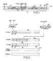
- Fig. 1 is a diagram of a sector on a track of a disk.
- Fig. 2 is a diagram of codewords.
- Fig. 3 is a flow chart of codeword generation.
- Figs. 4, 5 are block diagrams of encoders.
- Fig. 6 is a block diagram of an encoding and recording circuit.
- Fig. 7 is a diagram of three codewords
- Fig. 8 is a flowchart of codeword decoding.
- Fig. 9 is a block diagram of a decoding and sector identification circuit.
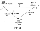
- Fig. 10 is a diagram of the distance properties of two codes.
- Fig. 11 is a block diagram of a decoder.
- Fig. 12 is a flow chart for decoding a codeword.
- Fig. 13 is a block diagram of a parallel recursive decoder circuit.
- Fig. 14 is a flow chart corresponding to Fig. 13.
- each track 10 of a magnetic disk is divided into sectors on which bits are recorded.
- Each sector 12 includes a sequence of fields that are scanned in order by a read head moving in the direction indicated by arrow 14.
- the first field is a string of leading heroes 16 used by a phase locked loop in a disk controller (not shown) to synchronize the operation of the read head with the bit spacing along the track.
- the second field 18 is a synchronization pattern which indicates that the data will appear next on the track.
- a short gap 20 follows the synchronization pattern.
- the encoded header for a given sector (which is prerecorded on the disk at the time of manufacture or formatting) is encoded using the address, bsf (bad sector flag), and scn (servo correction number) values that pertain to that sector by the following procedure.
- the bsf and scn values are expressed (29) as a pair of 5-bit symbols 30 and the address is expressed (31, Fig. 3) as a string of six 5-bit symbols 32.
- the bsf/scn symbol pair 30 is encoded (33) as a codeword C(33,2) in a Reed-Solomon maximum distance separable and cyclic (33,2) distance 32 code, (described below).
- the codeword C(33,2) has two leading symbols 34, 36 (identical to the bsf/scn symbol pair 30) followed by thirty-one 5-bit redundancy symbols 42.
- the six symbol address string 32 is encoded (35) as a (33,8) distance 26 Reed Solomon codeword, C(33,8).
- the code (described below) is arranged such that C(33,8) has two leading zero-valued symbols, followed by a six-symbol string 38 (identical to string 32) followed by twenty-five redundancy symbols 40.
- F(33,8) comprises two leading symbols 44, 46 identical to the bsf/scn symbol pair, followed by six symbols 50 in which both redundancy and address information are imbedded (in this sense F(33,8) is not systematic). The remaining twenty-five symbols 52 are imbedded with redundancy information from both C(33,2) and C(33,8).
- F(33,8) is a codeword in the original (33,8) code because both C(33,8) and C(33,2) are codewords in the (33,8) code. Note that the codes are designed so that every (33,2) codeword is in the (33,8) code.
- F(33,8) is exclusively ORed (39) with a thirty-three symbol coset leader 54 to form an adjusted final codeword G (33,8).
- the coset leader is chosen to reduce the chance of mistaken bit and/or symbol synchronization during decoding.
- One example of a good coset leader is The coset leader has no terms for X25 through X32 and thus does not alter the high order eight symbols of F(33,8).
- the (33,8) distance 26 code is a code over a Galois field GF(25) generated by the primitive polynomial x5 (+) x4 (+) x3 (+) x2 (+) 1 where (+) denotes exclusive OR, and x denotes an indeterminate or variable.
- the recursive polynomial is easier to implement, as follows.
- the bsf and scn symbols are initially entered respectively in a pair of one-symbol-interval delay elements 60, 62.
- the output 61 of delay element 60 is a stream of symbols making up C(33,2), with the highest order symbol in the codeword appearing first.
- the output of delay element 60 is also fed to an exclusive OR element 64, whose second input is the alpha7 element of GF(25) multiplied by the output of delay element 62.
- the block alpha7 (labeled 66) performs the multiplication.
- the output of element 64 is in turn fed back to delay element 62.
- Encoder 58 is cycled 33 times to generate the 33 symbols of the codeword.
- the codeword C(33,8) for any given header address similarly may be generated either by the following generator polynomial: or by the corresponding recursive polynomial:
- the encoder for C(33,8) may be configured either as an 8-stage linear shift register connected according to the recursive polynomial or a 25-stage linear shift register connected according to the generator polynomial.
- the encoder 57 would include eight delay elements 68 , eight exclusive OR elements 70, and eight multiply-by-alpha elements 72 (the number in each block 72 identifies the alpha value). Initially two leading zeroes and the six address symbols are loaded into the delay elements, the encoder is cycled 33 times, and the output 69 is C (33,8) beginning with the two high order zero symbols.
- a disk 80 is prerecorded by disk recording device 82 with headers that define the sectors of the disk.
- Each header is a word G(33,8) generated from an exclusive OR element 84 in which F(33,8) and a coset leader 86 are combined.
- F(33,8) is generated in exclusive OR element 88 from C(33,2) and C(33,8) which are derived from encoders 57, 58.
- Each header address read from the disk need not be fully decoded, but merely analyzed sufficiently to be certain that it could be accurately and fully decoded to give the desired address. So long as the number of symbol errors is no greater than T, it is certain that the present sector is the desired one.
- the bsf/scn symbols must be fully decoded in order to determine if the sector is good and to control the position of the head relative to the center line of the track.
- the bsf information may be used, for example, during a write operation, to avoid writing in a bad sector.
- the first step in decoding is to generate (90) a prototype codeword C'(33,8) based on the six-symbol desired address, e.g., MNPQRS, using the same kind of encoder 57 as for encoding. Note that if there were no recording errors, C'(33,8) would equal C(33,8) for the sector being sought.
- MNPQRS six-symbol desired address
- the next step is to exclusively OR (92) C'(33,8) with F'(33,8), the version of F(33,8) derived by reading the encoded header address G'(33,8) recorded on the disk. This is done in exclusive OR element 93.
- F'(33,8) is derived from G'(33,8) simply by exclusively ORing it with the original coset leader in exclusive OR element 91. Note that F'(33,8) will be a corrupted version of F(33,8) for example because of bit errors which may have occurred during reading of G(33,8) on the disk.
- the exclusive OR step (92) strips from F'(33,8) the information contained in C'(33,8) and leaves a possibly corrupted version C'(33,2) of the original codeword C(33,2).
- the next step is to decode (94) C'(33,2) over GF(25) in permutation decoder 95 to generate a value equal to the number of symbol errors in the header (as described below).
- the number of errors is compared (96) with a threshhold T in a comparator 97. If the number of errors is no greater than T, the decoder signals that the header address is the one being sought (98) and the fully decoded values bsf and scn are delivered (102) to the disk controller. Otherwise the decoder signals (100) that the number of errors is too great for proper decoding, indicating either that the desired sector has not been reached or that the number of errors in the header of the desired sector is too great to be corrected.
- C'(33,8) differs from C(33,8), (that is the current header address is not the one being sought) then C'(33,2) will not be a legitimate codeword of the (33,2) code but will be a legitimate codeword of the (33,8) code and thus will have a distance of at least 26 from any legitimate (33,2) codeword (because the (33,8) code has distance 26 and we know C'(33,2) is not a (33,2) codeword).
- F'(33,8) is not the same as F(33,8)
- C'(33,2) is no farther than some number T symbols from a legitimate codeword C(33,2)
- C'(33,2) may be presumed to be a corrupted version of a legitimate (33,2) codeword, thus implying that the header address used to derive C'(33,2) from F'(33,8) was the same one used to generate F(33,8) in the first place.
- the codeword C'(33,2) would not be a corrupted version of a legitimate codeword of the (33,2) code but rather a corrupted version of a legitimate codeword of the (33,8) code (because it is a concatenation of corrupted versions of legitimate (33,8) codewords), and would therefore be farther than T symbols from a legitimate C(33,2) codeword.
- the value T is chosen not as large as the number of symbols that can be corrected (judging from the minimum distance of the (33,2) code), but only as large as the number of symbols that might be corrected by the (33,8) code.
- the threshold T is chosen as follows.
- the current sector is the one we are looking for, that is C'(33,2) is a corrupted version of a legitimate codeword C(33,2).
- C'(33,2) lies at location 144 between two legitimate (33,2) codewords: the correct codeword C(33,2) (at location 140) and CB (at location 142).
- C(33,2) and CB are of course 32 apart so that C'(33,2) can be correctly decoded to C(33,2) provided there are no more than 15 erroneous symbols in C'(33,2).
- C'(33,2) will not be a corrupted version of a legitimate (33,2) codeword, but rather a corrupted version of a legitimate (33,8) codeword.
- C'(33,2) is in fact a (33,8) codeword, for example the one labeled 150 in Fig. 10.
- (33,2) codewords 140, 142 are also (33,8) codewords (the (33,2) codewords are a subset of the (33,8) codewords).
- codeword 150 is only 26 away from codewords 120, 122.
- C'(33,2) is decoded by a permutation decoder 110 which is like the encoder for the (33,2) code connected in accordance with the generator polynomial.
- the (33,2) code is completely decodable by permutation decoding.
- the goal of the permutation decoding is to find two correct adjacent symbols anywhere in the 33-symbol word.
- Decoder 110 is a linear feedback shift register of 31 delay elements 112 (numbered 30-i to 0-i respectively) with the delay elements separated by exclusive OR elements 114.
- the second input to each exclusive OR element is from an alpha block 116 which generates the product of the indicated alpha value times the value on line 118.
- the left-most delay element feeds an exclusive OR element 120 whose other input is delivered on line 122.
- the two high order symbols of C'(33,2) are fed (121) to input line 122.
- the alpha blocks 116 perform their multiplications and the results are exclusively ORed with the outputs of the respective delay elements (i.e., zero symbols); those results are stored in the next adjacent delay elements.
- the contents of the thirty-one delay elements represent the parity check symbols of the two symbols most recently fed in.
- the next step is to exclusively OR (in the exclusive OR elements 117) each of the 31 parity check symbols with the corresponding 31 parity check symbols in F'(33,8) retrieved from the disk.
- the decoder is shifted (125) without entering any new symbols at input 122.
- the threshold T indicating either that the two information symbols contain errors or that there are more than a correctable number of errors in the 31 parity symbols
- the decoder is shifted (125) without entering any new symbols at input 122.
- the number of non-zero parity symbols is counted. If T or fewer non-zero parity symbols appear in the delay elements after a given shift (127), the scn and bsf symbols are corrected and delivered along with a signal indicating that the desired sector has been found (129). Otherwise, once 2*T shifts have been completed (131) the system signals that the errors are uncorrectable (133).
- the only error patterns that need to be considered are those for symbols 32 and 31 (i.e., the two high order symbols corresponding to scn and bsf).
- the error patterns for those symbols are found by the following rule. If there are no more than T non-zero parity symbols at shift i then the error pattern for symbol 32 is symbol i-1 and the error pattern for symbol 31 is symbol i-2 of the delay elements. If i-1 is negative, then symbol 32 is error free.
- decoding may be accomplished using encoders configured according to the recursive polynomial as in Fig. 4.
- a dedicated encoder 58 is provided for encoding each one of 33 different pairs as a (33,2) codeword (161).
- Each of the 33 different pairs is one of the adjacent two symbols in the codeword C'(33,2).
- the qth encoded codeword is then compared to C'(33,2) in a comparator 160 to determine the number of symbol errors (163).
- the number of symbol errors is then compared (165) with the threshold T in a comparator 162.
- the outputs of all comparators 162 are connected to logic 164.
- logic 164 If all of the outputs of comparators 162 indicate that the threshold has been exceeded then logic 164 signals that the errors are uncorrectable. Otherwise logic 164 signals that the desired sector has been found and delivers the values of bsf and scn corresponding to the possible symbol pair that produced the sufficiently low number of symbol errors (167).
- the code In a startup mode, when the header address is usually not known in advance, in order to recover the bsf and scn symbols, the code must be decoded as a (33,8) code. Depending on the number of errors to be corrected, there are several possible approaches.
- the first 32 symbols are divided into four sets of eight symbols each. With no more than three symbol errors this guarantees that at least one of the eight-symbol sets is error free.
- the permutation decoding is done by finding the error-free symbol set using an encoder configured either serially in accordance with G8(X) or in parallel (as in Fig. 13) in accordance with the recursive polynomial H8(X). Once found, all errors in the thirty-three symbol word can be corrected.
- a full decoder for correcting twelve errors is also possible.
- the decoding is done over GF(210) rather than over GF(25).
Landscapes
- Engineering & Computer Science (AREA)
- Physics & Mathematics (AREA)
- Probability & Statistics with Applications (AREA)
- Theoretical Computer Science (AREA)
- Mathematical Physics (AREA)
- Signal Processing (AREA)
- Algebra (AREA)
- General Physics & Mathematics (AREA)
- Pure & Applied Mathematics (AREA)
- Multimedia (AREA)
- Signal Processing For Digital Recording And Reproducing (AREA)
- Error Detection And Correction (AREA)
Abstract
Claims (28)
- Procédé servant à déterminer si des informations particulières ont été utilisées lors du codage d'un mot de code codé précédemment (F'(33,8)) qui a été formé en codant des informations (32) en tant que première séquence de code préliminaire (40) conformément à un premier code, et en combinant ladite première séquence de code préliminaire avec une seconde séquence de code préliminaire (42) générée conformément à un second code, caractérisé en ce que ledit mot de code codé précédemment est décodé en:
codant lesdites informations particulières en tant que première séquence de code préliminaire particulière (C'(33,8)) conformément audit premier code,
retirant dudit mot de code codé précédemment ladite première séquence de code préliminaire particulière en exécutant entre eux une opération OU exclusif, pour obtenir une séquence d'essai qui est différente dudit mot de code codé précédemment ou d'un fragment quelconque de ce dernier,
décodant ladite séquence d'essai conformément audit second code, et
déterminant, sur la base d'une évaluation d'erreurs suivant ledit décodage, si lesdites informations particulières ont été utilisées lors du codage dudit mot de code codé précédemment. - Procédé selon la revendication 1, dans lequel les séquences de code légitimes dudit second code constituent un sous-ensemble des séquences de code légitimes dudit premier code.
- Procédé selon la revendication 1, dans lequel ledit mot de code codé précédemment est une séquence de code légitime dudit premier code.
- Procédé selon la revendication 1, dans lequel ledit premier code n'est pas systématique par rapport auxdites informations particulières.
- Procédé selon la revendication 1, dans lequel ledit premier code est un code (n, k) de correction d'erreur cyclique et ledit second code est un code (n,m) de correction d'erreur cyclique où m est inférieur à k.
- Procédé selon la revendication 1, dans lequel ledit second code est susceptible d'être décodé intégralement par décodage à permutation mais ledit premier code n'est pas susceptible d'être décodé intégralement par décodage à permutation.
- Procédé selon la revendication 1, dans lequel lesdits premier et second codes sont des codes Reed-Solomon.
- Procédé selon la revendication 1 dans lequel ledit premier code est un code (33,8) et ledit second code est un code (33,2).
- Procédé selon la revendication 1, adapté en outre pour le codage d'informations additionnelles dans ledit mot de code codé précédemment et dans lequel, sans le décodage intégral d'une version éventuellement altérée dudit mot de code codé précédemment, lesdites informations additionnelles peuvent être reconstruites intégralement à partir dudit mot de code altéré, consistant:
à coder lesdites informations additionnelles dans ladite seconde séquence de code préliminaire, et
a reconstruire lesdites informations additionnelles sur la base dudit décodage. - Procédé selon la revendication 1, dans lequel lesdites informations comportent une adresse (32) d'un bloc de données se trouvant sur un support d'enregistrement.
- Procédé selon la revendication 10, dans lequel ledit bloc comporte un secteur (12) d'un disque magnétique.
- Procédé selon la revendication 9, dans lequel lesdites informations additionnelles comportent un drapeau de secteur défectueux (BSF) pour disque magnétique.
- Procédé selon la revendication 9, dans lequel lesdites informations additionnelles comportent un numéro de correction asservie (SCN) pour disque magnétique.
- Procédé selon la revendication 1, consistant en outre:
à combiner ladite première séquence de code préliminaire et ladite seconde séquence de code préliminaire avec un caractère initial co-établi (54) pour former ledit mot de code codé précédemment, et
éliminer ledit caractère initial co-établi d'une version éventuellement altérée dudit mot de code codé précédemment avant ledit retrait de ladite première séquence de code préliminaire. - Procédé selon la revendication 9, dans lequel ledit second code est systématique par rapport auxdites informations additionnelles.
- Procédé selon la revendication 9, dans lequel ledit mot de code codé précédemment comporte une chaîne de n symboles, les m symboles de poids fort parmi lesdits symboles constituant lesdites informations additionnelles.
- Procédé selon la revendication 1, dans lequel ladite séquence de code préliminaire comporte une chaîne de A symboles, les k symboles de poids fort parmi lesdits symboles comportant au moins un symbole zéro suivi desdites informations.
- Procédé selon la revendication 1, dans lequel ledit décodage comporte le décodage à permutation sur un champ d'éléments finis comportant moins d'éléments que le champ qui serait requis pour le décodage intégral dudit mot de code altéré.
- Procédé selon la revendication 1, dans lequel ladite détermination consiste à détecter la distance séparant ladite séquence d'essai et des séquences de code légitimes dudit second code.
- Procédé selon la revendication 19, dans lequel ladite détermination comporte en outre la comparaison entre ladite distance et une valeur de seuil prédéterminée.
- Procédé selon la revendication 20, dans lequel ledit seuil prédéterminé a une valeur maximale qui est inférieure à la capacité de correction d'erreurs dudit second code.
- Procédé selon la revendication 21, dans lequel ledit seuil prédéterminé est le même que la capacité de correction d'erreurs dudit premier code.
- Procédé selon la revendication 1, dans lequel lesdits premier et second codes constituent des codes à distance maximale de séparation, ledit premier code présentant une distance inférieure à celle dudit second code.
- Procédé selon la revendication 9, dans lequel ledit décodage consiste:
à coder simultanément en parallèle, conformément audit second code, des séquences de code possibles correspondant à chaque valeur possible desdites informations additionnelles, et
à comparer simultanément en parallèle chaque séquence de code possible à ladite séquence d'essai. - Appareil pour déterminer si des informations particulières ont été utilisées lors du codage d'un mot de code codé précédemment (F'(33,8)) qui a été formé en codant des informations (32) en tant que première séquence de code préliminaire (40) conformément à un premier code, et en combinant ladite première séquence de code préliminaire avec une seconde séquence de code préliminaire (42) générée conformément à un second code, caractérisé en ce que ledit appareil comporte:
un codeur pour coder lesdites informations particulières en tant que première séquence de code préliminaire particulière (C'(33,8)) conformément audit premier code,
un décodeur comportant:(i) des moyens pour retirer dudit mot de code codé précédemment ladite première séquence de code préliminaire particulière en exécutant entre eux une opération OU exclusif pour obtenir une séquence d'essai qui diffère dudit mot de code codé précédemment ou d'un fragment quelconque de ce dernier,(ii) des moyens pour décoder ladite séquence d'essai conformément audit second code, et(iii) des moyens pour déterminer, sur la base d'une évaluation d'erreurs suivant ledit décodage, si lesdits informations particulières ont été utilisées lors du codage dudit mot de code codé précédemment. - Procédé selon la revendication 1, adapté en outre pour localiser un secteur (12) d'un disque magnétique, dans lequel l'adresse (32) dudit secteur est codé lors de ladite première séquence de code préliminaire, consistant en outre:
à enregistrer ledit mot de code codé précédemment dans ledit secteur au cours du formatage dudit disque magnétique,
à extraire ledit mot de code codé précédemment, éventuellement altéré, dudit secteur tournant sous une tête,
à coder l'adresse souhaitée dans ladite première séquence de code préliminaire particulière,
à comparer le nombre d'erreurs de la dite séquence d'essai à un seuil T, et
si le nombre d'erreurs n'est pas supérieur à T, à accepter le secteur en tant que secteur recherché, sinon à passer au secteur suivant. - Procédé selon la revendication 1, adapté en outre pour localiser un secteur inutilisable en écriture (12) sur un disque magnétique lors d'une opération d'écriture, dans lequel l'adresse (32) dudit secteur est codée dans ladite première séquence de code préliminaire, et des informations (30) de commande asservie et de secteur défectueux sont codées dans ladite seconde séquence de code préliminaire , consistant en outre:
à enregistrer ledit mot de code codé précédemment dans ledit secteur au cours du formatage dudit disque magnétique,
à extraire ledit mot de code codé précédemment, éventuellement altéré, dudit secteur tournant sous une tête,
à comparer le nombre d'erreurs de ladite séquence d'essai à un seuil T, et
si le nombre d'erreurs n'est pas supérieur à T, à accepter les informations de secteur défectueux décodées et à utiliser les informations de commande asservie décodées pour commander la position de ladite tête, autrement non. - Procédé selon la revendication 1, adapté en outre pour centrer une tête sur une piste d'un disque magnétique, dans lequel l'adresse (32) d'un secteur (12) est codée dans ladite première séquence de code préliminaire, et des informations (30) de commande asservie et de secteur défectueux sont codées dans ladite seconde séquence de code préliminaire, consistant en outre:
à enregistrer ledit mot de code codé précédemment dans ledit secteur lors du formatage dudit disque magnétique,
à extraire ledit mot de code codé précédemment, éventuellement altéré, dudit secteur tournant sous ladite tête,
à comparer le nombre d'erreurs de ladite séquence d'essai à un seuil T, et
si le nombre d'erreurs n'est pas supérieur à T, à utiliser lesdites informations de commande asservie pour commander l'emplacement de ladite tête.
Applications Claiming Priority (2)
| Application Number | Priority Date | Filing Date | Title |
|---|---|---|---|
| US17964688A | 1988-04-08 | 1988-04-08 | |
| US179646 | 1988-04-08 |
Publications (2)
| Publication Number | Publication Date |
|---|---|
| EP0365634A1 EP0365634A1 (fr) | 1990-05-02 |
| EP0365634B1 true EP0365634B1 (fr) | 1993-10-20 |
Family
ID=22657409
Family Applications (1)
| Application Number | Title | Priority Date | Filing Date |
|---|---|---|---|
| EP19890904394 Expired - Lifetime EP0365634B1 (fr) | 1988-04-08 | 1989-03-14 | Procede et appareil pour encodage consistant a former un mot code par combinaison d'une premiere sequence de code avec une seconde sequence de code |
Country Status (4)
| Country | Link |
|---|---|
| EP (1) | EP0365634B1 (fr) |
| JP (1) | JPH02502330A (fr) |
| DE (1) | DE68910078D1 (fr) |
| WO (1) | WO1989010029A1 (fr) |
Families Citing this family (5)
| Publication number | Priority date | Publication date | Assignee | Title |
|---|---|---|---|---|
| IT1241429B (it) * | 1990-03-01 | 1994-01-17 | Sip | Circuito elettronico per la generazione di codici per la rilevazione di errori in segnali numerici |
| AU4601097A (en) * | 1996-10-01 | 1998-04-24 | Symbios Logic Inc. | A method of data protection |
| RU2214047C2 (ru) * | 1997-11-19 | 2003-10-10 | Самсунг Электроникс Ко., Лтд. | Способ и устройство для масштабируемого кодирования/декодирования аудиосигналов |
| KR100354531B1 (ko) * | 1998-05-06 | 2005-12-21 | 삼성전자 주식회사 | 실시간 복호화를 위한 무손실 부호화 및 복호화 시스템 |
| US6463564B1 (en) * | 1999-09-14 | 2002-10-08 | Maxtor Corporation | Mis-synchronization detection system |
Family Cites Families (9)
| Publication number | Priority date | Publication date | Assignee | Title |
|---|---|---|---|---|
| US3638182A (en) * | 1970-01-02 | 1972-01-25 | Bell Telephone Labor Inc | Random and burst error-correcting arrangement with guard space error correction |
| JPS574629A (en) * | 1980-05-21 | 1982-01-11 | Sony Corp | Data transmitting method capable of correction of error |
| WO1982003719A1 (fr) * | 1981-04-16 | 1982-10-28 | Odaka Kentaro | Procede de codage de correction d'erreurs |
| US4434487A (en) * | 1981-10-05 | 1984-02-28 | Digital Equipment Corporation | Disk format for secondary storage system |
| JPH0767088B2 (ja) * | 1983-02-18 | 1995-07-19 | ソニー株式会社 | エラ−訂正符号化方法 |
| JPS60185263A (ja) * | 1984-03-02 | 1985-09-20 | Hitachi Ltd | エラ−訂正方式 |
| ATE50429T1 (de) * | 1985-06-14 | 1990-02-15 | Philips Nv | System zum uebertragen von worten, gesichert bei einer kombination eines blockcodes und eines rekurrenten kodes, uebertragungsgeraet zur verwendung in solchem system und empfaengergeraet zur verwendung in solchem system. |
| JPS6246468A (ja) * | 1985-08-23 | 1987-02-28 | Hitachi Ltd | デイスク記憶装置 |
| JPS62192975A (ja) * | 1986-02-20 | 1987-08-24 | Alps Electric Co Ltd | ハ−ドデイスク制御方式 |
-
1989
- 1989-03-14 EP EP19890904394 patent/EP0365634B1/fr not_active Expired - Lifetime
- 1989-03-14 DE DE89904394T patent/DE68910078D1/de not_active Expired - Lifetime
- 1989-03-14 WO PCT/US1989/001050 patent/WO1989010029A1/fr not_active Ceased
- 1989-03-14 JP JP1503889A patent/JPH02502330A/ja active Pending
Also Published As
| Publication number | Publication date |
|---|---|
| WO1989010029A1 (fr) | 1989-10-19 |
| DE68910078D1 (de) | 1993-11-25 |
| JPH02502330A (ja) | 1990-07-26 |
| EP0365634A1 (fr) | 1990-05-02 |
Similar Documents
| Publication | Publication Date | Title |
|---|---|---|
| US5237574A (en) | Error-resilient information encoding | |
| EP0117287B1 (fr) | Méthode pour corriger les erreurs dans les données numériques et système utilisant une telle méthode | |
| US8190963B1 (en) | Error correction using error detection codes | |
| US8495454B2 (en) | Methods, apparatuses, systems, and architectures for quickly and reliably encoding and/or decoding system data | |
| US5491701A (en) | Burst error corrector | |
| US5946328A (en) | Method and means for efficient error detection and correction in long byte strings using integrated interleaved Reed-Solomon codewords | |
| US6421805B1 (en) | Rogue packet detection and correction method for data storage device | |
| JPH0436487B2 (fr) | ||
| US5528607A (en) | Method and apparatus for protecting data from mis-synchronization errors | |
| CN101174839A (zh) | 编码装置、解码装置、编码/解码装置及记录/再现装置 | |
| EP0349687B1 (fr) | Méthode et appareil pour encoder les adresses des secteurs d'un disque magnétique | |
| US7478313B2 (en) | Encoding apparatus and method, and decoding apparatus and method for error correction | |
| US7127660B2 (en) | Method, apparatus and program storage device for correcting a burst of errors together with a random error using shortened cyclic codes | |
| EP0365634B1 (fr) | Procede et appareil pour encodage consistant a former un mot code par combinaison d'une premiere sequence de code avec une seconde sequence de code | |
| JP4527255B2 (ja) | 同期エラーを検出するためのシステムおよび方法 | |
| US4989211A (en) | Sector mis-synchronization detection method | |
| US4675870A (en) | Method of and apparatus for decoding a data stream which is protected by a multi-symbol error protection code | |
| US6868517B1 (en) | Method and apparatus for checking read errors with two cyclic redundancy check stages | |
| US6640319B1 (en) | Mis-synchronization detection system | |
| US6856660B1 (en) | Signal processing method and apparatus and disk device using the method and apparatus | |
| EP1232499B1 (fr) | Procede de detection de paquet indesirable et de correction pour dispositif de stockage de donnees | |
| JP3338320B2 (ja) | バースト誤り訂正方法及び装置 | |
| KR20040014723A (ko) | 에러 정정을 위한 부호화 장치 및 방법과 복호화 장치 및방법 | |
| JPH01238230A (ja) | 誤り訂正方式 |
Legal Events
| Date | Code | Title | Description |
|---|---|---|---|
| PUAI | Public reference made under article 153(3) epc to a published international application that has entered the european phase |
Free format text: ORIGINAL CODE: 0009012 |
|
| 17P | Request for examination filed |
Effective date: 19891220 |
|
| AK | Designated contracting states |
Kind code of ref document: A1 Designated state(s): DE FR GB IT NL |
|
| 17Q | First examination report despatched |
Effective date: 19911223 |
|
| GRAA | (expected) grant |
Free format text: ORIGINAL CODE: 0009210 |
|
| AK | Designated contracting states |
Kind code of ref document: B1 Designated state(s): DE FR GB IT NL |
|
| PG25 | Lapsed in a contracting state [announced via postgrant information from national office to epo] |
Ref country code: NL Effective date: 19931020 Ref country code: FR Effective date: 19931020 Ref country code: DE Effective date: 19931020 |
|
| REF | Corresponds to: |
Ref document number: 68910078 Country of ref document: DE Date of ref document: 19931125 |
|
| ITF | It: translation for a ep patent filed | ||
| EN | Fr: translation not filed | ||
| PG25 | Lapsed in a contracting state [announced via postgrant information from national office to epo] |
Ref country code: GB Effective date: 19940314 |
|
| NLV1 | Nl: lapsed or annulled due to failure to fulfill the requirements of art. 29p and 29m of the patents act | ||
| PLBE | No opposition filed within time limit |
Free format text: ORIGINAL CODE: 0009261 |
|
| STAA | Information on the status of an ep patent application or granted ep patent |
Free format text: STATUS: NO OPPOSITION FILED WITHIN TIME LIMIT |
|
| 26N | No opposition filed | ||
| GBPC | Gb: european patent ceased through non-payment of renewal fee |
Effective date: 19940314 |
|
| PG25 | Lapsed in a contracting state [announced via postgrant information from national office to epo] |
Ref country code: IT Free format text: LAPSE BECAUSE OF NON-PAYMENT OF DUE FEES;WARNING: LAPSES OF ITALIAN PATENTS WITH EFFECTIVE DATE BEFORE 2007 MAY HAVE OCCURRED AT ANY TIME BEFORE 2007. THE CORRECT EFFECTIVE DATE MAY BE DIFFERENT FROM THE ONE RECORDED. Effective date: 20050314 |