EP0365710B1 - Verfahren und Vorrichtung zum Extrudieren von Kunststoffschaumstoff - Google Patents
Verfahren und Vorrichtung zum Extrudieren von Kunststoffschaumstoff Download PDFInfo
- Publication number
- EP0365710B1 EP0365710B1 EP88117987A EP88117987A EP0365710B1 EP 0365710 B1 EP0365710 B1 EP 0365710B1 EP 88117987 A EP88117987 A EP 88117987A EP 88117987 A EP88117987 A EP 88117987A EP 0365710 B1 EP0365710 B1 EP 0365710B1
- Authority
- EP
- European Patent Office
- Prior art keywords
- chamber
- liquid
- pond
- level
- extrudate
- Prior art date
- Legal status (The legal status is an assumption and is not a legal conclusion. Google has not performed a legal analysis and makes no representation as to the accuracy of the status listed.)
- Expired - Lifetime
Links
- 238000001125 extrusion Methods 0.000 title claims abstract description 27
- 239000006260 foam Substances 0.000 title claims abstract description 21
- 238000000034 method Methods 0.000 title claims abstract description 10
- 239000007788 liquid Substances 0.000 claims abstract description 48
- 239000004033 plastic Substances 0.000 claims description 5
- XLYOFNOQVPJJNP-UHFFFAOYSA-N water Substances O XLYOFNOQVPJJNP-UHFFFAOYSA-N 0.000 abstract description 33
- 238000001816 cooling Methods 0.000 description 5
- 238000007493 shaping process Methods 0.000 description 3
- 238000010276 construction Methods 0.000 description 2
- 238000009434 installation Methods 0.000 description 2
- 238000004519 manufacturing process Methods 0.000 description 2
- 238000004891 communication Methods 0.000 description 1
- 230000003247 decreasing effect Effects 0.000 description 1
- 239000012530 fluid Substances 0.000 description 1
- 239000006261 foam material Substances 0.000 description 1
- 239000004620 low density foam Substances 0.000 description 1
- 239000000463 material Substances 0.000 description 1
- 239000007921 spray Substances 0.000 description 1
- 238000005507 spraying Methods 0.000 description 1
- 229920001169 thermoplastic Polymers 0.000 description 1
- 239000004416 thermosoftening plastic Substances 0.000 description 1
Images
Classifications
-
- B—PERFORMING OPERATIONS; TRANSPORTING
- B29—WORKING OF PLASTICS; WORKING OF SUBSTANCES IN A PLASTIC STATE IN GENERAL
- B29C—SHAPING OR JOINING OF PLASTICS; SHAPING OF MATERIAL IN A PLASTIC STATE, NOT OTHERWISE PROVIDED FOR; AFTER-TREATMENT OF THE SHAPED PRODUCTS, e.g. REPAIRING
- B29C44/00—Shaping by internal pressure generated in the material, e.g. swelling or foaming ; Producing porous or cellular expanded plastics articles
- B29C44/34—Auxiliary operations
- B29C44/3403—Foaming under special conditions, e.g. in sub-atmospheric pressure, in or on a liquid
- B29C44/3407—Vacuum extrusion using underwater barometric leg
-
- B—PERFORMING OPERATIONS; TRANSPORTING
- B29—WORKING OF PLASTICS; WORKING OF SUBSTANCES IN A PLASTIC STATE IN GENERAL
- B29C—SHAPING OR JOINING OF PLASTICS; SHAPING OF MATERIAL IN A PLASTIC STATE, NOT OTHERWISE PROVIDED FOR; AFTER-TREATMENT OF THE SHAPED PRODUCTS, e.g. REPAIRING
- B29C44/00—Shaping by internal pressure generated in the material, e.g. swelling or foaming ; Producing porous or cellular expanded plastics articles
- B29C44/34—Auxiliary operations
- B29C44/3403—Foaming under special conditions, e.g. in sub-atmospheric pressure, in or on a liquid
-
- B—PERFORMING OPERATIONS; TRANSPORTING
- B29—WORKING OF PLASTICS; WORKING OF SUBSTANCES IN A PLASTIC STATE IN GENERAL
- B29C—SHAPING OR JOINING OF PLASTICS; SHAPING OF MATERIAL IN A PLASTIC STATE, NOT OTHERWISE PROVIDED FOR; AFTER-TREATMENT OF THE SHAPED PRODUCTS, e.g. REPAIRING
- B29C44/00—Shaping by internal pressure generated in the material, e.g. swelling or foaming ; Producing porous or cellular expanded plastics articles
- B29C44/34—Auxiliary operations
- B29C44/36—Feeding the material to be shaped
- B29C44/46—Feeding the material to be shaped into an open space or onto moving surfaces, i.e. to make articles of indefinite length
- B29C44/50—Feeding the material to be shaped into an open space or onto moving surfaces, i.e. to make articles of indefinite length using pressure difference, e.g. by extrusion or by spraying
-
- B—PERFORMING OPERATIONS; TRANSPORTING
- B29—WORKING OF PLASTICS; WORKING OF SUBSTANCES IN A PLASTIC STATE IN GENERAL
- B29C—SHAPING OR JOINING OF PLASTICS; SHAPING OF MATERIAL IN A PLASTIC STATE, NOT OTHERWISE PROVIDED FOR; AFTER-TREATMENT OF THE SHAPED PRODUCTS, e.g. REPAIRING
- B29C48/00—Extrusion moulding, i.e. expressing the moulding material through a die or nozzle which imparts the desired form; Apparatus therefor
- B29C48/25—Component parts, details or accessories; Auxiliary operations
- B29C48/92—Measuring, controlling or regulating
-
- B—PERFORMING OPERATIONS; TRANSPORTING
- B29—WORKING OF PLASTICS; WORKING OF SUBSTANCES IN A PLASTIC STATE IN GENERAL
- B29C—SHAPING OR JOINING OF PLASTICS; SHAPING OF MATERIAL IN A PLASTIC STATE, NOT OTHERWISE PROVIDED FOR; AFTER-TREATMENT OF THE SHAPED PRODUCTS, e.g. REPAIRING
- B29C2791/00—Shaping characteristics in general
- B29C2791/004—Shaping under special conditions
- B29C2791/006—Using vacuum
-
- B—PERFORMING OPERATIONS; TRANSPORTING
- B29—WORKING OF PLASTICS; WORKING OF SUBSTANCES IN A PLASTIC STATE IN GENERAL
- B29C—SHAPING OR JOINING OF PLASTICS; SHAPING OF MATERIAL IN A PLASTIC STATE, NOT OTHERWISE PROVIDED FOR; AFTER-TREATMENT OF THE SHAPED PRODUCTS, e.g. REPAIRING
- B29C2948/00—Indexing scheme relating to extrusion moulding
- B29C2948/92—Measuring, controlling or regulating
- B29C2948/92009—Measured parameter
- B29C2948/92019—Pressure
-
- B—PERFORMING OPERATIONS; TRANSPORTING
- B29—WORKING OF PLASTICS; WORKING OF SUBSTANCES IN A PLASTIC STATE IN GENERAL
- B29C—SHAPING OR JOINING OF PLASTICS; SHAPING OF MATERIAL IN A PLASTIC STATE, NOT OTHERWISE PROVIDED FOR; AFTER-TREATMENT OF THE SHAPED PRODUCTS, e.g. REPAIRING
- B29C2948/00—Indexing scheme relating to extrusion moulding
- B29C2948/92—Measuring, controlling or regulating
- B29C2948/92323—Location or phase of measurement
- B29C2948/92428—Calibration, after-treatment, or cooling zone
-
- B—PERFORMING OPERATIONS; TRANSPORTING
- B29—WORKING OF PLASTICS; WORKING OF SUBSTANCES IN A PLASTIC STATE IN GENERAL
- B29C—SHAPING OR JOINING OF PLASTICS; SHAPING OF MATERIAL IN A PLASTIC STATE, NOT OTHERWISE PROVIDED FOR; AFTER-TREATMENT OF THE SHAPED PRODUCTS, e.g. REPAIRING
- B29C2948/00—Indexing scheme relating to extrusion moulding
- B29C2948/92—Measuring, controlling or regulating
- B29C2948/92504—Controlled parameter
- B29C2948/92514—Pressure
-
- B—PERFORMING OPERATIONS; TRANSPORTING
- B29—WORKING OF PLASTICS; WORKING OF SUBSTANCES IN A PLASTIC STATE IN GENERAL
- B29C—SHAPING OR JOINING OF PLASTICS; SHAPING OF MATERIAL IN A PLASTIC STATE, NOT OTHERWISE PROVIDED FOR; AFTER-TREATMENT OF THE SHAPED PRODUCTS, e.g. REPAIRING
- B29C2948/00—Indexing scheme relating to extrusion moulding
- B29C2948/92—Measuring, controlling or regulating
- B29C2948/92819—Location or phase of control
- B29C2948/92923—Calibration, after-treatment or cooling zone
Definitions
- This invention relates generally to a foam extrusion apparatus and method, and more particularly one such method and apparatus utilizing a large horizontal vacuum chamber.
- thermoplastic foam bodies known (EP-A-0 260 948) to provide an extrusion die on a bulkhead plate at one end within a vacuum chamber.
- the foamed extrudate is cooled within the vacuum chamber by spraying liquid onto the surface of the endless extrudate so that it is not in contact with the body of fluid within said vacuum chamber.
- the liquid level in the vacuum chamber is lower than the liquid level outside the vacuum chamber.
- a foam extrusion system and method employs a horizontal vacuum chamber with a bulkhead and extrusion die at one end of the chamber, the extrusion die being inside the chamber when the bulkhead is closed.
- a liquid baffle preferably water, is provided at the opposite end of the chamber through which the extrudate passes from the chamber to atmosphere.
- the baffle comprises a pond of liquid having a higher level in the chamber and a lower level outside the chamber. The higher level of the pond is formed between a dam plate and a seal plate, the latter forming the opposite end of the chamber.
- the seal plate includes a size adjustable window through which the extrudate passes, the extrudate being guided by a conveyor to extend inclined downwardly into the pond and to exit through the seal plate and pond with a large radius upwardly curved section.
- the level of liquid in the chamber is controlled by circulating liquid from the higher level of the pond within the chamber to the lower level of the pond outside the chamber with the amount of liquid circulated being inversely proportional to the absolute pressure in the vacuum chamber.
- the circulated liquid may pass through a cooler to control the liquid temperature.
- the size adjustment of the window or exit orifice in the seal plate may be used to control the flow of liquid from the lower level pond portion outside the chamber to higher level pond portion inside the chamber, particularly during start up.
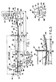
- FIG. 1 there is illustrated a large elongated horizontally extending vacuum chamber 10 which includes a bulkhead 11 at one end and a seal plate 12 at the opposite end.
- the chamber is substantially elongated and is horizontal throughout its length and is in the form of a large diameter pipe.
- the chamber may be formed of interconnected and sealed large diameter concrete pipe sections such as shown in US-A-4,199,310.
- the bulkhead 11 may be mounted for movement on a carriage 14 for movement toward and away from the end of the vacuum chamber 10.
- On the exterior of the bulkhead 11 there is provided one or more extruders 15 while an extrusion die 16 is on the interior of the bulkhead.
- Also mounted on the interior of the bulkhead are shaping rolls to control the configuration and shape of the extrudate exiting the die.
- the vacuum chamber may be opened and closed by moving the bulkhead 11 horizontally toward and away from the end of the chamber.
- dam plate 20 Positioned in the chamber fairly close to the bulkhead 11 is a dam plate 20, the upper edge 21 of which extends somewhat above a horizontal centerline of the chamber.
- a containment structure 24 Positioned outside the chamber beyond the seal plate 12 is a containment structure 24 which includes side walls 25 and 26 and an end wall 27 remote from the chamber 10. The opposite end wall 28 of the containment structure 24 includes the seal plate 12.
- the containment structure 24 together with the vacuum chamber 10 forms a containment for a pond 30 of liquid, preferably water, extending from the dam plate 20 to the containment structure wall 27.
- a portion 31 of the pond is outside the vacuum chamber 10 while a portion 32 is inside the vacuum chamber.
- Such portions are on opposite sides of the seal plate 12 and communication between such portions is obtained by a window 34 in seal plate 12.
- a vertically movable gate 36 mounted on the seal plate and driven vertically by a motor 37 controls the size of the opening of window 34.
- the foam extrudate 40 leaves the die 16 to expand and be shaped and then passes under the end 42 or tail pulley of a conveyor belt 43 which is inclined downwardly to bring the extrudate below the level of the pond 30 in the vacuum chamber 10.
- the foam extrudate will float up against the conveyor belt, and the speed of the conveyor belt is closely controlled to draw the foam extrudate from the vacuum chamber.
- the conveyor belt 43 passes through the window 34 and then curves upwardly as indicated at 45 terminating in head pulley 46 driven from drive 47.
- the curvature of the conveyor belt need not necessarily be uniform but in no case should the curvature be on a radius less than 50 m.
- the gate 36 When the gate 36 is in its most closed position it provides fairly close clearance for the conveyor 43 and extrudate 40 and acts as a gross flow control valve for water moving from the portion 31 of the pond 30 outside of the chamber to the portion 32 inside the chamber, particularly during start-up.
- two water circulation pumps 50 and 51 which draw water from the bottom of the vacuum chamber as indicated at 52 and 53, respectively, just inside the dam plate 20.
- the outlet of the pumps passes through check valves 54 and 55, respectively, and through power operated valves 56 and 57, also respectively.
- Such power operated valves are in pump outlet lines 59 and 60, respectively, which extend to cooling tower 61 through respective valves 62 and 63.
- the cooling tower may be bypassed by closing the valves 62 and 63 and causing the water to flow through lines 64 and 65 leading directly into the pond 31 outside of the vacuum chamber.
- Such lines may also include respective valves 66 and 67 which are opened and closed alternately with valves 62 and 63. Water from the cooling tower 61 returns to the pond 31 through line 69, again outside of the vacuum chamber.
- each pump is provided with inlet and outlet shut off valves 72 and 73 as well as a pressure gauge 74.
- the pumps may be utilized concurrently or separately.
- Vacuum is established in the vacuum chamber 10 by one or more vacuum pumps 77.
- the vacuum level is controlled by vacuum controller 78 through an air bleed valve 79.
- the vacuum controller 78 is also electronically connected to both level control 80 and motor 37, the latter controlling the position of gate 36 on the seal plate.
- the level controller connection is by a set point control connection 81.
- the level controller 80 is connected to both the vacuum and water sides of the vacuum chamber through valves 83 and 84.
- the level controller in turn controls level control valves 56 and 57 in the pump discharge lines 59 and 60, respectively.
- the vacuum chamber 10 just to the inside of the dam plate 20 is provided with a sump and drain 86 in the event water splashes over the top 21 of the dam plate.
- the pumps 50 and 51 function to draw water from the portion 32 of the pond within the vacuum chamber and deliver that water either directly or through the cooling tower to the portion 31 of the pond outside the vacuum chamber or exposed to atmosphere. The water thus flows from one end of the pond to the other and circulates back through the adjustable window 34 in the seal plate 12.
- the water level on both sides of the seal plate 12 will be at a common level.
- the pumps 50 and 51 are turned on but the level control valves 56 and 57 are closed.
- the vacuum controller 78 being set to a desired level, turns on the vacuum pumps 77.
- the vacuum level goes up (absolute pressure goes down) water will be drawn from the exterior of the chamber into the interior of the chamber causing the water level on the interior of the chamber to rise.
- the level controller begins to open the level control valves 56 and 57 and the vacuum controller begins to close gate 36 through motor 37.
- the control of the gate 36 reducing the size of the orifice acts as a gross flow control valve for water moving into the vacuum chamber.
- Both the vacuum controller 78 and the level controller 80 have optimum adjustable set points. When the vacuum controller 78 reaches its set point, it begins to maintain the desired vacuum level by actuating the bleed valve 79. When the level controller 80 reaches its set point it will begin to modulate the level control valves 56 and 57 maintaining the water level within the vacuum chamber within a given narrow range simply by increasing or decreasing the flow or circulation of water from the vacuum chamber to the atmospheric portion of the pond 31. As the vacuum level increases, the water level inside the vacuum chamber increases and in order to maintain the water level at an acceptable level the water flow through the valves 56 and 57 also increases. During operation of the system the vacuum controller resets the level controller 80 on a continuing basis which in turn modulates the level control valves 56 and 57.
- the vacuum controller is the master and the level controller is the slave.
- the vacuum controller By resetting the level controller constantly, the vacuum controller then can anticipate changes in the water level thus maintaining a precise water level inside the vacuum chamber in response to the vacuum level.
- the gate 36 once in its final position, will normally stay in that position and is used as such gross flow control valve only during start up or shut down of the system.
- the full system permits the water level inside the vacuum chamber to be controlled in response to the vacuum level within the chamber thus obviating the necessity for a long and inclined barometric leg.
- the system may also operate with less total volume of water.
- a foam extrusion line which includes an elongated horizontally extending chamber with the chamber being horizontal throughout its length.
- the chamber is provided with an extrusion die at one end forming a foam extrudate within the chamber and a water baffle at the opposite end to enable the chamber to be maintained under vacuum.
- the foam extrudate is guided through the baffle to atmosphere for subsequent cutting and processing.
- the liquid In order to maintain the liquid level within the vacuum the liquid is circulated from the higher level of liquid within the vacuum chamber to the lower level of liquid outside the chamber during extrusion. The amount of liquid circulated is inversely proportional to the absolute pressure in the vacuum chamber.
Landscapes
- Engineering & Computer Science (AREA)
- Mechanical Engineering (AREA)
- Extrusion Moulding Of Plastics Or The Like (AREA)
- Casting Or Compression Moulding Of Plastics Or The Like (AREA)
- Processing And Handling Of Plastics And Other Materials For Molding In General (AREA)
Claims (10)
- Eine Vorrichtung für das Extrudieren von Kunstschaumstoffen mit einer Vakuumkammer (10), einer Spundwand (11) und einer Preßmatrize (16) an einem Ende der Kammer, einer Tauchwand für Flüssigkeit an dem gegenüberliegenden Ende der Kammer, das die Kammer abdichtet und durch das das Preßgut (40) aus der Kammer an die Atmosphäre austritt, wobei die Tauchwand für Flüssigkeit ein eine Flüssigkeit enthaltendes Becken (30) enthält, das innerhalb der Kammer einen höheren Flüssigkeitsstand (32) und außerhalb der Kammer einen niedrigeren Flüssigkeitstand (31) aufweist, sowie mit Mitteln (50, 51) für das Zirkulieren während der Extrudierung von Flüssigkeit von dem höheren Flüssigkeitsstand zu dem niedrigeren Flüssigkeitsstand, um den höheren Flüssigkeitsstand in der Kammer aufrechtzuerhalten, und mit Mitteln (43), um das Preßgut in das Becken mit dem höheren Flüssigkeitsstand in der Kammer und dann durch die Tauchwand für Flüssigkeit zu leiten, um aus dem außerhalb der Kammer befindlichen Becken mit dem niedrigeren Flüssigkeitstand in die Atmosphäre auszutreten.
- Eine Vorrichtung für das Extrudieren von Kunstschaumstoffen nach Anspruch 1,
dadurch gekennzeichnet, daß
die Menge der zirkulierten Flüssigkeit umgekehrt proportional zu dem in der Vakuumkammer (10) herrschenden absoluten Druck ist. - Eine Vorrichtung für das Extrudieren von Kunstschaumstoffen nach einem der Ansprüche 1 oder 2,
dadurch gekennzeichnet, daß
die Kammer (10) horizontal verläuft und daß das Preßgut (40) nach unten in das Becken (32) mit dem höheren Flüssigkeitsstand in der Kammer geleitet wird. - Eine Vorrichtung für das Extrudieren von Kunstschaumstoffen nach einem der Ansprüche 1 bis 3,
dadurch gekennzeichnet, daß
eine Dämmplatte (20) innerhalb der Kammer (10) und eine Abdichtplatte (12) am Ende der Kammer gegenüber der Strangpreßmatrize (16) vorgesehen ist, um das Becken (32) mit dem höheren Flüssigkeitsstand in der Kammer zu bilden. - Eine Vorrichtung für das Extrudieren von Kunstschaumstoffen nach Anspruch 4,
dadurch gekennzeichnet, daß
eine Auslaßöffnung (34) für das Preßgut (40) in der Abdichtplatte (12) unterhalb des Flüssigkeitsstandes des Beckens vorgesehen ist, sowie Mittel (37), um die Abmessung der Auslaßöffnung zu steuern. - Eine Vorrichtung für das Extrudieren von Kunstschaumstoffen nach Anspruch 5,
dadurch gekennzeichnet, daß
die Mittel (37) für die Steuerung der Abmessung der Auslaßöffnung (34) ein durch einen Motor (37) angetriebenes Gatter (36) in der Abdichtplatte (12) aufweisen. - Ein Verfahren für die Herstellung von Kunstschaumstoffen, in dem eine schäumbare Kunststoffschmelze in eine Vakuumkammer extrudiert wird und das geschäumte Preßgut (40) in einen Flüssigkeitskörper (30) geleitet wird, welcher sich teilweise innerhalb und teilweise außerhalb der Kammer (10) befindet, um durch diesen Flüssigkeitskörper aus der Kammer auszutreten, wobei dieser Flüssigkeitskörper innerhalb der Kammer (10) einen höheren Stand und außerhalb der Kammer einen niedrigeren Stand aufweist, wobei der Stand dieses Teils (32) des Flüssigkeitskörpers (30) in der Kammer (10), in den das Preßgut (40) gelangt, dadurch gesteuert wird, daß Flüssigkeit aus diesem Teil (32) innerhalb der Kammer (10) in den Teil (31) außerhalb der Kammer (10), aus dem das Preßgut in die Atmosphäre austritt, zirkuliert wird.
- Ein Verfahren nach Anspruch 7,
dadurch gekennzeichnet, daß
die Menge der zirkulierten Flüssigkeit umgekehrt proportional zu dem in der Vakuumkammer (10) herrschenden absoluten Druck ist. - Ein Verfahren nach einem der Ansprüche 7 oder 8,
dadurch gekennzeichnet, daß
der Steuerungsschritt den Schritt der Steuerung eines in der Auslaßleitung (59, 60) einer Umwälzpumpe (50, 51) vorgesehenen Steuerventils (56, 57) beinhaltet. - Ein verfahren nach Anspruch 9,
dadurch gekennzeichnet, daß
das Steuerventil (56, 57) für den Flüssigkeitsstand durch eine Steuerung (80) für Flüssigkeitsstand gesteuert wird.
Applications Claiming Priority (1)
| Application Number | Priority Date | Filing Date | Title |
|---|---|---|---|
| US07/080,680 US4783291A (en) | 1987-08-03 | 1987-08-03 | Method and apparatus for foam extrusion into a vacuum chamber having a liquid baffle with control of the liquid level |
Publications (3)
| Publication Number | Publication Date |
|---|---|
| EP0365710A2 EP0365710A2 (de) | 1990-05-02 |
| EP0365710A3 EP0365710A3 (en) | 1990-07-04 |
| EP0365710B1 true EP0365710B1 (de) | 1993-02-24 |
Family
ID=22158932
Family Applications (1)
| Application Number | Title | Priority Date | Filing Date |
|---|---|---|---|
| EP88117987A Expired - Lifetime EP0365710B1 (de) | 1987-08-03 | 1988-10-28 | Verfahren und Vorrichtung zum Extrudieren von Kunststoffschaumstoff |
Country Status (6)
| Country | Link |
|---|---|
| US (1) | US4783291A (de) |
| EP (1) | EP0365710B1 (de) |
| AT (1) | ATE85941T1 (de) |
| AU (1) | AU620823B2 (de) |
| DE (1) | DE3878692T2 (de) |
| ES (1) | ES2037794T3 (de) |
Families Citing this family (19)
| Publication number | Priority date | Publication date | Assignee | Title |
|---|---|---|---|---|
| US5120481A (en) * | 1989-02-28 | 1992-06-09 | U.C. Industries, Inc. | Process for preparing extruded foam bodies |
| US5008051A (en) * | 1989-03-01 | 1991-04-16 | Decoursey Robert T | Vacuum sizing tank with electronically controlled vacuum pressure |
| US5242289A (en) * | 1992-10-20 | 1993-09-07 | The Conair Group, Inc. | Apparatus for providing controlled cooling of thermoplastic strands |
| US5464335A (en) * | 1994-08-30 | 1995-11-07 | The Conair Group, Inc. | Vacuum tank for vacuum sizing apparatus |
| US6036468A (en) * | 1997-08-21 | 2000-03-14 | Owens Corning Fiberglas Technology, Inc. | Vacuum extrusion system |
| US6116882A (en) * | 1996-08-14 | 2000-09-12 | Owens Corning Fiberglas Technology, Inc. | Sealable chamber extrusion apparatus with seal controls |
| US6113374A (en) * | 1996-08-14 | 2000-09-05 | Owens Corning Fiberglass Technology, Inc. | Foam extrusion apparatus |
| US5753161A (en) * | 1996-08-14 | 1998-05-19 | Owens-Corning Fiberglas Technology, Inc. | Vacuum extrusion system and method |
| US6093350A (en) * | 1996-08-14 | 2000-07-25 | Owens Corning Fiberglas Technology, Inc. | Sealable chamber extrusion apparatus and method with process controls |
| US5783122A (en) * | 1996-08-14 | 1998-07-21 | Owens Corning Fiberglas Technology, Inc. | Vacuum extrusion apparatus and method |
| US6372812B1 (en) | 2001-02-20 | 2002-04-16 | Foamex L.P. | Higher support, lower density cushioning foams |
| US8557884B2 (en) * | 2002-05-31 | 2013-10-15 | Owens Corning Intellectual Capital, Llc | To enhance the thermal insulation of polymeric foam by reducing cell anisotropic ratio and the method for production thereof |
| US6740687B2 (en) * | 2002-08-14 | 2004-05-25 | Foamex L.P. | Latex replacement polyurethane foams with improved flame retardancy |
| US6716890B1 (en) | 2003-01-30 | 2004-04-06 | Foamex L.P. | Polyurethane foams with fine cell size |
| US7150614B2 (en) * | 2003-12-18 | 2006-12-19 | Owens Corning Fiberglas Technology, Inc. | Horizontal vacuum chamber seal control device |
| US20060029788A1 (en) * | 2004-08-04 | 2006-02-09 | Foamex L.P. | Lower density, thermoformable, sound absorbing polyurethane foams |
| CN103862607B (zh) * | 2012-12-18 | 2018-01-16 | 海尔集团公司 | 太阳能水箱卧式发泡生产线及生产工艺 |
| CN110039740A (zh) * | 2019-03-05 | 2019-07-23 | 泉州台商投资区万鼎机械科技有限公司 | 一种pvc给水管生产用牵引机 |
| CN112757550A (zh) * | 2021-02-18 | 2021-05-07 | 北鹏建材集团股份有限公司 | 一种发泡装置 |
Family Cites Families (4)
| Publication number | Priority date | Publication date | Assignee | Title |
|---|---|---|---|---|
| US3704083A (en) * | 1970-06-18 | 1972-11-28 | Arthus L Phipps | Extrusion machine |
| US4044084A (en) * | 1975-08-11 | 1977-08-23 | Phipps Arthur L | Method of removing an article from a chamber having a reduced pressure therein |
| AU609736B2 (en) * | 1986-09-19 | 1991-05-09 | Dow Chemical Company, The | Process and apparatus for producing extruded thermoplastic foam bodies |
| AU608533B2 (en) * | 1986-09-19 | 1991-04-11 | Dow Chemical Company, The | Fluidized vacuum seal |
-
1987
- 1987-08-03 US US07/080,680 patent/US4783291A/en not_active Expired - Lifetime
-
1988
- 1988-10-28 EP EP88117987A patent/EP0365710B1/de not_active Expired - Lifetime
- 1988-10-28 DE DE8888117987T patent/DE3878692T2/de not_active Expired - Lifetime
- 1988-10-28 AT AT88117987T patent/ATE85941T1/de not_active IP Right Cessation
- 1988-10-28 ES ES198888117987T patent/ES2037794T3/es not_active Expired - Lifetime
- 1988-10-31 AU AU24527/88A patent/AU620823B2/en not_active Expired
Also Published As
| Publication number | Publication date |
|---|---|
| AU620823B2 (en) | 1992-02-27 |
| EP0365710A2 (de) | 1990-05-02 |
| DE3878692T2 (de) | 1993-06-09 |
| EP0365710A3 (en) | 1990-07-04 |
| ATE85941T1 (de) | 1993-03-15 |
| DE3878692D1 (en) | 1993-04-01 |
| AU2452788A (en) | 1990-05-03 |
| US4783291A (en) | 1988-11-08 |
| ES2037794T3 (es) | 1993-07-01 |
Similar Documents
| Publication | Publication Date | Title |
|---|---|---|
| EP0365710B1 (de) | Verfahren und Vorrichtung zum Extrudieren von Kunststoffschaumstoff | |
| US6113374A (en) | Foam extrusion apparatus | |
| AU732137B2 (en) | Sealable chamber extrusion apparatus and method with process controls | |
| KR100515183B1 (ko) | 진공 압출가공 시스템 및 방법 | |
| EP1044091B1 (de) | Extrusionsvorrichtung mit abdichtbarer kammer und verfahren zur steuerung der dichtung | |
| CA1315056C (en) | Foam extrusion apparatus and method | |
| IE62109B1 (en) | Foam extrusion apparatus and method | |
| KR970003929B1 (ko) | 포옴 압출 장치 및 방법 | |
| JP2636378B2 (ja) | 発泡体押出装置および方法 | |
| FI88891C (fi) | Extrusionsanordning foer skum och foerfarande foer framstaellning av skumplast | |
| DK173370B1 (da) | Anlæg og fremgangsmåde til ekstrudering af skumplast | |
| HU209572B (en) | Apparatus and process for extrusion of foaming material | |
| JP4954710B2 (ja) | 水平真空室密閉制御装置 | |
| CN118082146A (zh) | 一种pvc管材生产工艺 | |
| NO307037B1 (no) | Anlegg for ekstrudering av skum |
Legal Events
| Date | Code | Title | Description |
|---|---|---|---|
| PUAI | Public reference made under article 153(3) epc to a published international application that has entered the european phase |
Free format text: ORIGINAL CODE: 0009012 |
|
| AK | Designated contracting states |
Kind code of ref document: A2 Designated state(s): AT BE CH DE ES FR GB IT LI LU NL SE |
|
| PUAL | Search report despatched |
Free format text: ORIGINAL CODE: 0009013 |
|
| AK | Designated contracting states |
Kind code of ref document: A3 Designated state(s): AT BE CH DE ES FR GB IT LI LU NL SE |
|
| 17P | Request for examination filed |
Effective date: 19901116 |
|
| 17Q | First examination report despatched |
Effective date: 19910605 |
|
| GRAA | (expected) grant |
Free format text: ORIGINAL CODE: 0009210 |
|
| AK | Designated contracting states |
Kind code of ref document: B1 Designated state(s): AT BE CH DE ES FR GB IT LI LU NL SE |
|
| REF | Corresponds to: |
Ref document number: 85941 Country of ref document: AT Date of ref document: 19930315 Kind code of ref document: T |
|
| REF | Corresponds to: |
Ref document number: 3878692 Country of ref document: DE Date of ref document: 19930401 |
|
| ET | Fr: translation filed | ||
| ITF | It: translation for a ep patent filed | ||
| REG | Reference to a national code |
Ref country code: ES Ref legal event code: FG2A Ref document number: 2037794 Country of ref document: ES Kind code of ref document: T3 |
|
| PLBE | No opposition filed within time limit |
Free format text: ORIGINAL CODE: 0009261 |
|
| STAA | Information on the status of an ep patent application or granted ep patent |
Free format text: STATUS: NO OPPOSITION FILED WITHIN TIME LIMIT |
|
| EPTA | Lu: last paid annual fee | ||
| 26N | No opposition filed | ||
| EAL | Se: european patent in force in sweden |
Ref document number: 88117987.3 |
|
| REG | Reference to a national code |
Ref country code: GB Ref legal event code: 732E |
|
| REG | Reference to a national code |
Ref country code: CH Ref legal event code: PUE Owner name: U.C. INDUSTRIES, INC. TRANSFER- OWENS CORNING |
|
| PGFP | Annual fee paid to national office [announced via postgrant information from national office to epo] |
Ref country code: LU Payment date: 20011012 Year of fee payment: 14 |
|
| REG | Reference to a national code |
Ref country code: GB Ref legal event code: IF02 |
|
| PG25 | Lapsed in a contracting state [announced via postgrant information from national office to epo] |
Ref country code: LU Free format text: LAPSE BECAUSE OF NON-PAYMENT OF DUE FEES Effective date: 20021028 |
|
| PGFP | Annual fee paid to national office [announced via postgrant information from national office to epo] |
Ref country code: ES Payment date: 20071026 Year of fee payment: 20 Ref country code: DE Payment date: 20071130 Year of fee payment: 20 Ref country code: NL Payment date: 20071024 Year of fee payment: 20 |
|
| PGFP | Annual fee paid to national office [announced via postgrant information from national office to epo] |
Ref country code: CH Payment date: 20071030 Year of fee payment: 20 Ref country code: IT Payment date: 20071030 Year of fee payment: 20 Ref country code: AT Payment date: 20071003 Year of fee payment: 20 |
|
| PGFP | Annual fee paid to national office [announced via postgrant information from national office to epo] |
Ref country code: SE Payment date: 20071029 Year of fee payment: 20 Ref country code: BE Payment date: 20071107 Year of fee payment: 20 |
|
| PGFP | Annual fee paid to national office [announced via postgrant information from national office to epo] |
Ref country code: GB Payment date: 20071029 Year of fee payment: 20 Ref country code: FR Payment date: 20071017 Year of fee payment: 20 |
|
| REG | Reference to a national code |
Ref country code: CH Ref legal event code: PFA Owner name: OWENS CORNING Free format text: OWENS CORNING#ONE OWENS CORNING PARKWAY#TOLEDO, OHIO 43659 (US) -TRANSFER TO- OWENS CORNING#ONE OWENS CORNING PARKWAY#TOLEDO, OHIO 43659 (US) |
|
| BE20 | Be: patent expired |
Owner name: *U.C. INDUSTRIES INC. Effective date: 20081028 |
|
| REG | Reference to a national code |
Ref country code: CH Ref legal event code: PL |
|
| REG | Reference to a national code |
Ref country code: GB Ref legal event code: PE20 Expiry date: 20081027 |
|
| PG25 | Lapsed in a contracting state [announced via postgrant information from national office to epo] |
Ref country code: NL Free format text: LAPSE BECAUSE OF EXPIRATION OF PROTECTION Effective date: 20081028 |
|
| EUG | Se: european patent has lapsed | ||
| NLV7 | Nl: ceased due to reaching the maximum lifetime of a patent |
Effective date: 20081028 |
|
| REG | Reference to a national code |
Ref country code: ES Ref legal event code: FD2A Effective date: 20081029 |
|
| PG25 | Lapsed in a contracting state [announced via postgrant information from national office to epo] |
Ref country code: ES Free format text: LAPSE BECAUSE OF EXPIRATION OF PROTECTION Effective date: 20081029 |
|
| PG25 | Lapsed in a contracting state [announced via postgrant information from national office to epo] |
Ref country code: GB Free format text: LAPSE BECAUSE OF EXPIRATION OF PROTECTION Effective date: 20081027 |