EP0365714A1 - Procédé de démarrage à chaud - Google Patents
Procédé de démarrage à chaud Download PDFInfo
- Publication number
- EP0365714A1 EP0365714A1 EP88118031A EP88118031A EP0365714A1 EP 0365714 A1 EP0365714 A1 EP 0365714A1 EP 88118031 A EP88118031 A EP 88118031A EP 88118031 A EP88118031 A EP 88118031A EP 0365714 A1 EP0365714 A1 EP 0365714A1
- Authority
- EP
- European Patent Office
- Prior art keywords
- hot start
- internal combustion
- combustion engine
- cooling water
- water temperature
- Prior art date
- Legal status (The legal status is an assumption and is not a legal conclusion. Google has not performed a legal analysis and makes no representation as to the accuracy of the status listed.)
- Granted
Links
- 238000000034 method Methods 0.000 title claims abstract description 12
- 238000002485 combustion reaction Methods 0.000 claims abstract description 28
- 239000000498 cooling water Substances 0.000 claims abstract description 24
- 239000000446 fuel Substances 0.000 claims abstract description 20
- 238000002347 injection Methods 0.000 claims description 8
- 239000007924 injection Substances 0.000 claims description 8
- 230000015572 biosynthetic process Effects 0.000 description 2
- 238000010586 diagram Methods 0.000 description 2
- 238000011161 development Methods 0.000 description 1
- 230000018109 developmental process Effects 0.000 description 1
- 238000012544 monitoring process Methods 0.000 description 1
- 239000000243 solution Substances 0.000 description 1
Images

Classifications
-
- F—MECHANICAL ENGINEERING; LIGHTING; HEATING; WEAPONS; BLASTING
- F02—COMBUSTION ENGINES; HOT-GAS OR COMBUSTION-PRODUCT ENGINE PLANTS
- F02D—CONTROLLING COMBUSTION ENGINES
- F02D41/00—Electrical control of supply of combustible mixture or its constituents
- F02D41/02—Circuit arrangements for generating control signals
- F02D41/04—Introducing corrections for particular operating conditions
- F02D41/06—Introducing corrections for particular operating conditions for engine starting or warming up
- F02D41/062—Introducing corrections for particular operating conditions for engine starting or warming up for starting
- F02D41/065—Introducing corrections for particular operating conditions for engine starting or warming up for starting at hot start or restart
-
- F—MECHANICAL ENGINEERING; LIGHTING; HEATING; WEAPONS; BLASTING
- F02—COMBUSTION ENGINES; HOT-GAS OR COMBUSTION-PRODUCT ENGINE PLANTS
- F02D—CONTROLLING COMBUSTION ENGINES
- F02D2200/00—Input parameters for engine control
- F02D2200/02—Input parameters for engine control the parameters being related to the engine
- F02D2200/06—Fuel or fuel supply system parameters
- F02D2200/0606—Fuel temperature
-
- F—MECHANICAL ENGINEERING; LIGHTING; HEATING; WEAPONS; BLASTING
- F02—COMBUSTION ENGINES; HOT-GAS OR COMBUSTION-PRODUCT ENGINE PLANTS
- F02D—CONTROLLING COMBUSTION ENGINES
- F02D41/00—Electrical control of supply of combustible mixture or its constituents
- F02D41/02—Circuit arrangements for generating control signals
- F02D41/04—Introducing corrections for particular operating conditions
- F02D41/042—Introducing corrections for particular operating conditions for stopping the engine
Definitions
- the invention relates to a method for performing a hot start according to the preamble of claim 1.
- a method is e.g. B. described in laid-open specification 24 10 090.
- a hot start condition is recognized via the temperature of the cooling water.
- the cooling water temperature alone is not a reliable criterion for a hot start condition. It has therefore started to measure the temperature of the fuel directly with an additional temperature sensor. Although this method is precise, it requires an additional temperature sensor.
- the object of the invention is to reliably detect a hot start condition in a method for performing a hot start without having to use additional temperature sensors.
- the hot start condition is recognized from the cooling water temperature and the intake air temperature.
- the corresponding sensors for generating a cooling water temperature signal and an intake air temperature signal, which are monitored by an engine control unit, are present in any case in vehicles with engine control units and therefore do not require any additional effort.
- the engine control unit for monitoring these signals remains switched on after the internal combustion engine has been switched off during a post-operating period.
- This post-operating time is chosen so that after its expiration the internal combustion engine has cooled down in any case to such an extent that there can be no more hot start conditions.
- the engine control unit recognizes a hot start condition when the cooling water temperature signal and the intake air temperature signal have both each reached an assigned limit value at least once during the post-operating time. This is based on the finding that, without measuring the temperature of the fuel directly, the formation of vapor bubbles in the fuel can be recognized by the fact that the cooling water temperature and the intake air temperature both once reached these assigned limit values during the after-operation time.
- the cooling water temperature rises relatively quickly to a high maximum value due to the lack of circulation of the cooling water and the hot machine, and then drops slowly.
- the intake air temperature also rises to a significantly higher maximum value after being switched off by the hot engine, but normally does not reach this maximum value at the same time as the maximum value of the cooling water temperature is reached.
- limit values can be determined by tests and differ depending on the type of internal combustion engine. You don't necessarily have to be both at the same time. It is sufficient if, even at different times, each of the two limit values was reached once during the post-operation period. It can then be assumed that vapor bubbles have formed in the fuel during the post-operating time.
- the engine control unit stores a hot start identification and is then switched off.
- the hot start identifier remains saved.
- This second limit value for the cooling water temperature is lower than the first for recognizing the hot start condition. This is because after the appearance of vapor bubbles in the fuel, these continue to exist even when the machine cools down until the second lower limit value is reached. This second limit value is also determined by tests.
- An internal combustion engine is equipped with an engine control unit for controlling the fuel injection quantity.
- the engine control unit evaluates information such as the speed, load, etc. of the internal combustion engine and determines the required fuel injection quantity from a map.
- a further map for a hot start is provided, which causes an increased fuel injection quantity compared to the normal map.
- the engine control unit receives as input variables a cooling water temperature signal KW from a cooling water temperature sensor, an intake air temperature signal AL from an intake air temperature sensor and a signal from an ignition switch of the internal combustion engine, which indicates whether the internal combustion engine is stopped or is being started.
- the engine control unit executes a program routine according to the flow chart in FIGURE 1 with steps S1 to S11.
- step S1 a program run for recognizing a hot start condition is started after the arrival of the signal from the ignition switch that the internal combustion engine is stopped.
- step S2 a flag 1 and a flag 2 are then set to zero.
- step S3 it is checked whether a post-operating time TN has expired since the internal combustion engine was switched off.
- This post-operating time TN is thirty minutes. This value is determined from tests and selected so that after this time the hot engine under no circumstances occurs under any circumstances. Since the post-operating time TN is just beginning during the first program run, the answer in step S3 is no and step S4 follows.
- step S3 follows again after step S7 until the post-operating time TN has expired. Then the answer in step S3 is yes and the engine control unit is switched off in step S11 without a hot start identifier having been stored.
- Steps S5, 6, 8 and 9 now serve to set the hot start identifier in step S10 if the limit values GKW1 and GAL have each been exceeded once.
- the answer in step S4 will be no and in step S5 the flag 1 will be set to 1.
- Step S6 then serves to query whether flag 2 is also 1. This is only the case if the limit GAL has already been exceeded once in step S7 and flag 2 has accordingly been set to 1 in step S8.
- the hot start flag is set and stored in step S10.
- Steps S8 and S9 represent the same procedure for the limit value GAL as steps S5 and S6 for the limit value GKW1.
- step S11 If the engine control unit is switched off in step S11, two cases are possible: - The post-operating time TN has expired without a hot start condition being recognized; the hot start identifier is not set. - A hot start condition was detected during the post-operation time TN; the hot start identifier is set.
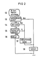
- the program routine described in the flowchart in FIGURE 2 then runs with steps S12 to S18. It is decided whether a hot start with an increased fuel injection quantity is necessary or whether a cold start is performed with the normal fuel injection quantity.
- step S13 it is checked whether the hot start flag is set. If it was not set, step S18 can immediately follow with the cold start, since then there was no hot start condition.
- step S14 follows with the query whether the cooling water temperature signal KW is greater than a limit value GKW2 of 80 ° C. If the answer is no, it means that the hot start condition has occurred once but is no longer present. Accordingly, the hot start identifier is deleted in step S17 and step S18 follows again.
- step S14 If the answer in step S14 is yes, the hot start condition is still given and the hot start is carried out in step S16.
- step S16 After the hot start in step S16 or the cold start in step S18, the normal engine running routine follows, which is no longer shown in FIG. 2.
- step S15 is intended for the case that the starting process is interrupted one or more times. In this case, a hot start was then carried out for the duration of these starting attempts, thus causing an increased fuel injection quantity. The intake tract of the internal combustion engine is then already sufficiently flushed with fuel and a hot start does not have to be carried out again.
- step S15 therefore, the time since the start of the start process or, if appropriate, the total time for several Startups compared to a post-start time. This post-start time is thirty seconds. If the answer is yes in step S15, the hot start identifier is then deleted in step S17 and the cold start is carried out in step S18. With a no answer in step S15, on the other hand, the hot start follows in step S16.
Landscapes
- Engineering & Computer Science (AREA)
- Chemical & Material Sciences (AREA)
- Combustion & Propulsion (AREA)
- Mechanical Engineering (AREA)
- General Engineering & Computer Science (AREA)
- Electrical Control Of Air Or Fuel Supplied To Internal-Combustion Engine (AREA)
- Combined Controls Of Internal Combustion Engines (AREA)
Priority Applications (4)
| Application Number | Priority Date | Filing Date | Title |
|---|---|---|---|
| DE8888118031T DE3864688D1 (de) | 1988-10-28 | 1988-10-28 | Verfahren zum durchfuehren eines heissstarts. |
| EP88118031A EP0365714B1 (fr) | 1988-10-28 | 1988-10-28 | Procédé de démarrage à chaud |
| ES88118031T ES2024001B3 (es) | 1988-10-28 | 1988-10-28 | Procedimiento para realiza un arranque en caliente |
| US07/416,994 US4951633A (en) | 1988-10-28 | 1989-10-02 | Hot start method for a combustion engine |
Applications Claiming Priority (1)
| Application Number | Priority Date | Filing Date | Title |
|---|---|---|---|
| EP88118031A EP0365714B1 (fr) | 1988-10-28 | 1988-10-28 | Procédé de démarrage à chaud |
Publications (2)
| Publication Number | Publication Date |
|---|---|
| EP0365714A1 true EP0365714A1 (fr) | 1990-05-02 |
| EP0365714B1 EP0365714B1 (fr) | 1991-09-04 |
Family
ID=8199503
Family Applications (1)
| Application Number | Title | Priority Date | Filing Date |
|---|---|---|---|
| EP88118031A Expired - Lifetime EP0365714B1 (fr) | 1988-10-28 | 1988-10-28 | Procédé de démarrage à chaud |
Country Status (4)
| Country | Link |
|---|---|
| US (1) | US4951633A (fr) |
| EP (1) | EP0365714B1 (fr) |
| DE (1) | DE3864688D1 (fr) |
| ES (1) | ES2024001B3 (fr) |
Cited By (8)
| Publication number | Priority date | Publication date | Assignee | Title |
|---|---|---|---|---|
| DE4338176A1 (de) * | 1992-11-16 | 1994-05-19 | Ford Werke Ag | Verfahren und Vorrichtung zur Modifikation eines Steuersignals für eine Einspritzdüse eines Kraftstoff-Fördersystems |
| WO1995006811A1 (fr) * | 1993-08-28 | 1995-03-09 | Ford Motor Company Limited | Systeme de gestion de moteur |
| FR2712634A1 (fr) * | 1993-11-15 | 1995-05-24 | Walbro Corp | Circuit de distribution de carburant pour moteur à combustion interne. |
| WO1996010690A1 (fr) * | 1994-10-04 | 1996-04-11 | Robert Bosch Gmbh | Systeme de regulation du dosage de carburant dans des moteurs a combustion interne |
| FR2741388A1 (fr) * | 1995-11-22 | 1997-05-23 | Siemens Ag | Procede d'injection de carburant dans un moteur a combustion interne avec compensation de temperature et dispositif pour la mise en oeuvre du procede |
| WO2002020966A1 (fr) * | 2000-09-04 | 2002-03-14 | Robert Bosch Gmbh | Procede pour determiner une situation de demarrage a chaud dans un moteur a combustion interne |
| DE4224893B4 (de) * | 1992-07-28 | 2006-12-07 | Robert Bosch Gmbh | Verfahren zur Kraftstoffzumessung für eine Brennkraftmaschine in Verbindung mit einem Heißstart |
| DE4039598B4 (de) * | 1990-12-12 | 2008-11-27 | Robert Bosch Gmbh | Heißstartverfahren und -Vorrichtung für eine Brennkraftmaschine |
Families Citing this family (9)
| Publication number | Priority date | Publication date | Assignee | Title |
|---|---|---|---|---|
| DE4029811C2 (de) * | 1990-09-20 | 1999-08-12 | Bosch Gmbh Robert | Katalysatorheizfunktion |
| US5179925A (en) * | 1992-01-30 | 1993-01-19 | General Motors Of Canada Limited | Hot restart compensation |
| US5577482A (en) * | 1992-10-15 | 1996-11-26 | Nippondenso Co., Ltd. | Fuel supply system for internal combustion engines |
| DE19644497B4 (de) * | 1996-10-25 | 2005-09-08 | Robert Bosch Gmbh | Verfahren zur Steuerung einer Brennkraftmaschine mit einer Kraftstoffpumpe |
| DE10064653A1 (de) * | 2000-12-22 | 2002-07-11 | Bosch Gmbh Robert | Verfahren und Vorrichtung zur Steuerung einer Brennkraftmaschine |
| JP3941441B2 (ja) * | 2001-09-11 | 2007-07-04 | トヨタ自動車株式会社 | 内燃機関の始動時制御装置 |
| DE10360024A1 (de) | 2003-12-19 | 2005-07-21 | Siemens Ag | Verfahren und Vorrichtung zum Steuern einer Brennkraftmaschine |
| CN102493905A (zh) * | 2011-12-15 | 2012-06-13 | 潍柴动力股份有限公司 | 一种柴油机冷启动辅助装置及控制方法 |
| CN110486173B (zh) * | 2019-07-30 | 2021-10-01 | 中国航发沈阳发动机研究所 | 一种用于航空发动机热起动供油的修正方法及装置 |
Citations (2)
| Publication number | Priority date | Publication date | Assignee | Title |
|---|---|---|---|---|
| US4224913A (en) * | 1979-08-13 | 1980-09-30 | General Motors Corporation | Vehicle air-fuel controller having hot restart air/fuel ratio adjustment |
| US4499879A (en) * | 1983-04-28 | 1985-02-19 | General Motors Corporation | Fuel supply system for an internal combustion engine |
Family Cites Families (7)
| Publication number | Priority date | Publication date | Assignee | Title |
|---|---|---|---|---|
| DE2410090C2 (de) * | 1974-03-02 | 1986-07-31 | Robert Bosch Gmbh, 7000 Stuttgart | Schalteinrichtung für den Heißstart von Brennkraftmaschinen mit elektronisch gesteuerter Kraftstoffeinspritzung |
| JPS56154133A (en) * | 1980-04-28 | 1981-11-28 | Nippon Denso Co Ltd | Correcting method of starting for electronic fuel jet system |
| JPS59206651A (ja) * | 1983-05-09 | 1984-11-22 | Toyota Motor Corp | エンジンの再始動制御方法 |
| JPS62131938A (ja) * | 1985-12-02 | 1987-06-15 | Nippon Denso Co Ltd | 内燃機関の空燃比制御装置 |
| JPH0830442B2 (ja) * | 1986-01-10 | 1996-03-27 | 本田技研工業株式会社 | 内燃エンジンの作動制御方法 |
| US4747386A (en) * | 1986-05-02 | 1988-05-31 | Toyota Jidosha Kabushiki Kaisha | Method and apparatus for augmenting fuel injection on hot restart of engine |
| JPH0751905B2 (ja) * | 1986-12-27 | 1995-06-05 | 本田技研工業株式会社 | 内燃エンジンの始動後燃料供給制御方法 |
-
1988
- 1988-10-28 EP EP88118031A patent/EP0365714B1/fr not_active Expired - Lifetime
- 1988-10-28 ES ES88118031T patent/ES2024001B3/es not_active Expired - Lifetime
- 1988-10-28 DE DE8888118031T patent/DE3864688D1/de not_active Expired - Lifetime
-
1989
- 1989-10-02 US US07/416,994 patent/US4951633A/en not_active Expired - Fee Related
Patent Citations (2)
| Publication number | Priority date | Publication date | Assignee | Title |
|---|---|---|---|---|
| US4224913A (en) * | 1979-08-13 | 1980-09-30 | General Motors Corporation | Vehicle air-fuel controller having hot restart air/fuel ratio adjustment |
| US4499879A (en) * | 1983-04-28 | 1985-02-19 | General Motors Corporation | Fuel supply system for an internal combustion engine |
Non-Patent Citations (2)
| Title |
|---|
| PATENT ABSTRACTS OF JAPAN, Band 10, Nr. 187 (M-493)[2243], 2. Juli 1986; & JP-A-61 31 633 (TOYOTA MOTOR CORP.) 14-02-1986 * |
| PATENT ABSTRACTS OF JAPAN, Band 10, Nr. 253 (M-512)[2309], 29. August 1986; & JP-A-61 81 551 (TOYOTA MOTOR CORP.) 25-04-1986 * |
Cited By (9)
| Publication number | Priority date | Publication date | Assignee | Title |
|---|---|---|---|---|
| DE4039598B4 (de) * | 1990-12-12 | 2008-11-27 | Robert Bosch Gmbh | Heißstartverfahren und -Vorrichtung für eine Brennkraftmaschine |
| DE4224893B4 (de) * | 1992-07-28 | 2006-12-07 | Robert Bosch Gmbh | Verfahren zur Kraftstoffzumessung für eine Brennkraftmaschine in Verbindung mit einem Heißstart |
| DE4338176A1 (de) * | 1992-11-16 | 1994-05-19 | Ford Werke Ag | Verfahren und Vorrichtung zur Modifikation eines Steuersignals für eine Einspritzdüse eines Kraftstoff-Fördersystems |
| WO1995006811A1 (fr) * | 1993-08-28 | 1995-03-09 | Ford Motor Company Limited | Systeme de gestion de moteur |
| FR2712634A1 (fr) * | 1993-11-15 | 1995-05-24 | Walbro Corp | Circuit de distribution de carburant pour moteur à combustion interne. |
| WO1996010690A1 (fr) * | 1994-10-04 | 1996-04-11 | Robert Bosch Gmbh | Systeme de regulation du dosage de carburant dans des moteurs a combustion interne |
| FR2741388A1 (fr) * | 1995-11-22 | 1997-05-23 | Siemens Ag | Procede d'injection de carburant dans un moteur a combustion interne avec compensation de temperature et dispositif pour la mise en oeuvre du procede |
| WO2002020966A1 (fr) * | 2000-09-04 | 2002-03-14 | Robert Bosch Gmbh | Procede pour determiner une situation de demarrage a chaud dans un moteur a combustion interne |
| US6874358B2 (en) | 2000-09-04 | 2005-04-05 | Robert Bosch Gmbh | Method for determining a hot-start situation in an internal combustion engine |
Also Published As
| Publication number | Publication date |
|---|---|
| US4951633A (en) | 1990-08-28 |
| ES2024001B3 (es) | 1992-02-16 |
| DE3864688D1 (de) | 1991-10-10 |
| EP0365714B1 (fr) | 1991-09-04 |
Similar Documents
| Publication | Publication Date | Title |
|---|---|---|
| EP0365714B1 (fr) | Procédé de démarrage à chaud | |
| DE4440127B4 (de) | Steuergerät | |
| EP0464041B1 (fr) | Procede pour determiner au moins une position terminale d'un dispositif d'ajustement dans un vehicule automobile | |
| EP0360826B1 (fr) | Dispositif de commande d'equipements techniques et de machines | |
| DE4139469A1 (de) | Elektrische stromquelle fuer elektrofahrzeuge | |
| DE3138102A1 (de) | Verfahren zur steuerung der zuendpunkteinstellung einer brennkraftmaschine | |
| EP1276981B1 (fr) | Procede d'ajustement d'un diagramme caracteristique d'adaptation d'un controle du cognement adaptatif d'un moteur a combustion interne et procede de controle du cognement adaptatif d'un moteur a combustion interne | |
| EP1217197A2 (fr) | Méthode et système pour contrôler la durée entre deux injections | |
| EP1122414A2 (fr) | Système de régulation du dosage de carburant dans un moteur à combustion interne | |
| DE4128909C2 (de) | Verfahren zur Zündzeitpunktsteuerung für eine Brennkraftmaschine | |
| EP0603543B1 (fr) | Méthode et dispositif de surveillance d'un dispositif de commande dans un moteur à combustion | |
| EP1347165B1 (fr) | Procédé et dispositif de commande du dosage de carburant pour un moteur à combustion interne | |
| DE19730970B4 (de) | Steuereinrichtung für eine Brennkraftmaschine | |
| DE19903549A1 (de) | Zylinderidentifizierungsvorrichtung für Brennkraftmaschinen | |
| DE19821561A1 (de) | Verfahren und Vorrichtung zur Ansteuerung eines elektromagnetischen Verbrauchers | |
| EP1264098B1 (fr) | Procede et dispositif de commande de l'injection de carburant dans un moteur a combustion interne | |
| EP0365528B1 (fr) | Systeme pour regler l'angle de la soupape d'etranglement | |
| DE4111875C2 (de) | Hilfsvorrichtung zum Starten eines Motors | |
| DE10043695A1 (de) | Verfahren zum Bestimmen einer Heißstartsituation bei einer Brennkraftmaschine | |
| DE4041630A1 (de) | Verfahren zum aufheizen der ansaugluft bei brennkraftmaschinen mittels einer flammstartanlage | |
| DE4303560B4 (de) | Verfahren und Vorrichtung zur Steuerung einer Verstelleinrichtung | |
| DE19860398A1 (de) | Verfahren und Vorrichtung zur Steuerung der Kraftstoffzumessung in eine Brennkraftmaschine | |
| EP0140152A2 (fr) | Dispositif de commande d'un moteur à combustion interne en décélération | |
| DE19644497B4 (de) | Verfahren zur Steuerung einer Brennkraftmaschine mit einer Kraftstoffpumpe | |
| DE3423663A1 (de) | Vorrichtung zum anlassen und abstellen einer brennkraftmaschine |
Legal Events
| Date | Code | Title | Description |
|---|---|---|---|
| PUAI | Public reference made under article 153(3) epc to a published international application that has entered the european phase |
Free format text: ORIGINAL CODE: 0009012 |
|
| AK | Designated contracting states |
Kind code of ref document: A1 Designated state(s): AT BE CH DE ES FR GB GR IT LI LU NL SE |
|
| RBV | Designated contracting states (corrected) |
Designated state(s): DE ES FR GB IT |
|
| 17P | Request for examination filed |
Effective date: 19901026 |
|
| 17Q | First examination report despatched |
Effective date: 19910214 |
|
| GRAA | (expected) grant |
Free format text: ORIGINAL CODE: 0009210 |
|
| AK | Designated contracting states |
Kind code of ref document: B1 Designated state(s): DE ES FR GB IT |
|
| REF | Corresponds to: |
Ref document number: 3864688 Country of ref document: DE Date of ref document: 19911010 |
|
| ET | Fr: translation filed | ||
| ITF | It: translation for a ep patent filed | ||
| GBT | Gb: translation of ep patent filed (gb section 77(6)(a)/1977) | ||
| REG | Reference to a national code |
Ref country code: ES Ref legal event code: FG2A Ref document number: 2024001 Country of ref document: ES Kind code of ref document: B3 |
|
| PLBE | No opposition filed within time limit |
Free format text: ORIGINAL CODE: 0009261 |
|
| STAA | Information on the status of an ep patent application or granted ep patent |
Free format text: STATUS: NO OPPOSITION FILED WITHIN TIME LIMIT |
|
| 26N | No opposition filed | ||
| PGFP | Annual fee paid to national office [announced via postgrant information from national office to epo] |
Ref country code: ES Payment date: 19941006 Year of fee payment: 7 |
|
| PG25 | Lapsed in a contracting state [announced via postgrant information from national office to epo] |
Ref country code: ES Free format text: LAPSE BECAUSE OF THE APPLICANT RENOUNCES Effective date: 19951030 |
|
| REG | Reference to a national code |
Ref country code: ES Ref legal event code: FD2A Effective date: 19991007 |
|
| REG | Reference to a national code |
Ref country code: GB Ref legal event code: IF02 |
|
| PG25 | Lapsed in a contracting state [announced via postgrant information from national office to epo] |
Ref country code: IT Free format text: LAPSE BECAUSE OF NON-PAYMENT OF DUE FEES;WARNING: LAPSES OF ITALIAN PATENTS WITH EFFECTIVE DATE BEFORE 2007 MAY HAVE OCCURRED AT ANY TIME BEFORE 2007. THE CORRECT EFFECTIVE DATE MAY BE DIFFERENT FROM THE ONE RECORDED. Effective date: 20051028 |
|
| PGFP | Annual fee paid to national office [announced via postgrant information from national office to epo] |
Ref country code: GB Payment date: 20071018 Year of fee payment: 20 Ref country code: FR Payment date: 20071022 Year of fee payment: 20 |
|
| PGFP | Annual fee paid to national office [announced via postgrant information from national office to epo] |
Ref country code: DE Payment date: 20071214 Year of fee payment: 20 |
|
| REG | Reference to a national code |
Ref country code: GB Ref legal event code: PE20 Expiry date: 20081027 |
|
| PG25 | Lapsed in a contracting state [announced via postgrant information from national office to epo] |
Ref country code: GB Free format text: LAPSE BECAUSE OF EXPIRATION OF PROTECTION Effective date: 20081027 |