EP0365717A1 - Méthode et dispositif pour la conversion d'un signal analogique d'entrée - Google Patents
Méthode et dispositif pour la conversion d'un signal analogique d'entrée Download PDFInfo
- Publication number
- EP0365717A1 EP0365717A1 EP88309067A EP88309067A EP0365717A1 EP 0365717 A1 EP0365717 A1 EP 0365717A1 EP 88309067 A EP88309067 A EP 88309067A EP 88309067 A EP88309067 A EP 88309067A EP 0365717 A1 EP0365717 A1 EP 0365717A1
- Authority
- EP
- European Patent Office
- Prior art keywords
- converter
- output
- value
- signal
- input
- Prior art date
- Legal status (The legal status is an assumption and is not a legal conclusion. Google has not performed a legal analysis and makes no representation as to the accuracy of the status listed.)
- Withdrawn
Links
Images
Classifications
-
- H—ELECTRICITY
- H03—ELECTRONIC CIRCUITRY
- H03M—CODING; DECODING; CODE CONVERSION IN GENERAL
- H03M1/00—Analogue/digital conversion; Digital/analogue conversion
- H03M1/12—Analogue/digital converters
- H03M1/18—Automatic control for modifying the range of signals the converter can handle, e.g. gain ranging
- H03M1/186—Automatic control for modifying the range of signals the converter can handle, e.g. gain ranging in feedforward mode, i.e. by determining the range to be selected directly from the input signal
- H03M1/187—Automatic control for modifying the range of signals the converter can handle, e.g. gain ranging in feedforward mode, i.e. by determining the range to be selected directly from the input signal using an auxiliary analogue/digital converter
Definitions
- the invention relates to a method for converting an analog input signal which is sampled during a sampling period of a working cycle, said sampling signal being held and converted into a digital exponent value, with which an amplification stage for the sampling signal is set, said amplifier signal likewise being sampled, held and is converted into a digital mantissa value during the hold, which is combined with the exponent value to form an output value in exponential representation, and the input signal is already sampled in the next working cycle while the amplifier signal is held.
- the invention has for its object to eliminate the use of this circuit.
- the places of an input memory holding the mantissa value are connected to the digital input of a mantissa D / A converter and the places of the input memory holding the exponent value are connected to a decoder the values of the decoder and the output signal of the mantissa D / A converter are fed to a second multiplying D / A converter and the output of the second multiplying D / A converter is connected to an analog output via a smoothing filter.
- the conversion of an analog audio signal into a 20-bit output value AW and its conversion back are described.
- the output value AW is processed digitally as a tone value in exponential representation.
- the input filter of the analog / digital converter module is made up of an echo filter AAF and a broadband filter NF.
- the AAA echo filter is a low-pass filter, the noise components above 24 kHz are removed by the broadband filter NF to reduce the overall noise level.
- a Butterworth filter is used as the broadband filter NF, which has a particularly good passage behavior.
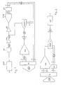
- the parallel A / D converter FAD operates continuously during the sampling period of the first sample and hold element SH1 and holds the value at the digital output during the hold period.
- the parallel A / D converter FAD generates a 6-bit value in about 300 ns, which is converted by a coder EC into a 4-bit exponent value EW in hexadecimal representation. This exponent value EW already represents the exponential component of the 20-bit output value AW of the module and is fed to an output memory OL.
- the exponent value EW acts as the input resistance of the first multiplying D / A converter MDAC1 with externally fixed amplification.
- a possible increase in the quantization distortion is avoided by using a feedback capacitor. With a 6-bit exponent value EW, this feedback capacitor would have to be switched on with a small gain. In this case it should also be noted that the capacitor is not overcharged and generates voltage peaks.
- the first multiplying D / A converter MDAC1 thus works as a digitally controlled amplifier. It controls the sample signal AS of the first sample and hold element SH1.
- the output of the first multiplying D / A converter MDAC1 is connected to the second sample and hold element SH2. This holds the signal at the output, while the parallel A / D converter FAD and the first multiplying D / A converter MDAC1 process the scanning signal AS of the following working cycle.
- a 16-bit mantissa A / D converter AD in the meantime converts the signal held by the second sample and hold element SH2 into a mantissa value MW as part of the output value AW.
- the mantissa value MW is combined in the output memory OL with the exponent value EW. It should be noted that the exponent value EW is buffered twice because the encoder EC is one period ahead in the work cycle.
- the use of the second sample-and-hold element SH2 increases the period of time available for performing the conversion operations. While a conversion cycle is completed by the mantissa A / D converter AD, the first sample-and-hold element SH1 already begins to sample the input signal ES for the following cycle. As a result of this time saving, no special operational amplifiers are required for the construction of the sample and hold elements SH1, SH2, and standard types (for example 5534) are sufficient.
- standard types for example 5534
- DC peaks can cause sensitive interference in the digital area of the converter modules. They become noticeable as quantization distortion when the output value AW is converted back into an analog signal. The occurrence of DC peaks must be prevented in particular in the area between the first and second multiplying D / A converters MDAC1, MDAC2. Outside of this range they are tolerable because they are balanced when the gain level is set.
- the noise level of the converter modules is about -80 dBu
- the frequency constancy is better than +/- 0.3 dB from 20 Hz - 20 kHz
- the distortion at +18 dBu is less than 0.04% (-67 dB) from 20 Hz - 20 kHz.
- the improvement over conventional 16-bit systems is more than 10 dB in noise level, more than 24 dB in signal conversion and about 10 dB in distortion.
Landscapes
- Engineering & Computer Science (AREA)
- Theoretical Computer Science (AREA)
- Analogue/Digital Conversion (AREA)
Priority Applications (2)
| Application Number | Priority Date | Filing Date | Title |
|---|---|---|---|
| EP88309067A EP0365717A1 (fr) | 1988-09-29 | 1988-09-29 | Méthode et dispositif pour la conversion d'un signal analogique d'entrée |
| PCT/EP1989/001128 WO1990003694A2 (fr) | 1988-09-29 | 1989-09-26 | Procede et dispositif pour convertir un signal analogique d'entree |
Applications Claiming Priority (1)
| Application Number | Priority Date | Filing Date | Title |
|---|---|---|---|
| EP88309067A EP0365717A1 (fr) | 1988-09-29 | 1988-09-29 | Méthode et dispositif pour la conversion d'un signal analogique d'entrée |
Publications (1)
| Publication Number | Publication Date |
|---|---|
| EP0365717A1 true EP0365717A1 (fr) | 1990-05-02 |
Family
ID=8200231
Family Applications (1)
| Application Number | Title | Priority Date | Filing Date |
|---|---|---|---|
| EP88309067A Withdrawn EP0365717A1 (fr) | 1988-09-29 | 1988-09-29 | Méthode et dispositif pour la conversion d'un signal analogique d'entrée |
Country Status (2)
| Country | Link |
|---|---|
| EP (1) | EP0365717A1 (fr) |
| WO (1) | WO1990003694A2 (fr) |
Cited By (1)
| Publication number | Priority date | Publication date | Assignee | Title |
|---|---|---|---|---|
| RU2134016C1 (ru) * | 1996-04-04 | 1999-07-27 | Фраунхофер-Гезелльшафт Цур Фердерунг Дер Ангевандтен Форшунг Е.Ф. | Способ кодирования оцифрованного с низкой частотой дискретизации аудиосигнала |
Families Citing this family (1)
| Publication number | Priority date | Publication date | Assignee | Title |
|---|---|---|---|---|
| DE102006058963A1 (de) * | 2006-12-14 | 2008-06-19 | Straussmann, Jürgen, Dipl.-Ing. | Digitales Kodierungsverfahren und Einrichtung zur Durchführung des Verfahrens |
Family Cites Families (1)
| Publication number | Priority date | Publication date | Assignee | Title |
|---|---|---|---|---|
| FR2492841B1 (fr) * | 1980-10-23 | 1983-07-22 | Agronomique Inst Nat Rech | Virus mutant de septicemie hemorragique virale, vaccin contenant ce mutant et procede pour sa preparation |
-
1988
- 1988-09-29 EP EP88309067A patent/EP0365717A1/fr not_active Withdrawn
-
1989
- 1989-09-26 WO PCT/EP1989/001128 patent/WO1990003694A2/fr not_active Ceased
Non-Patent Citations (3)
| Title |
|---|
| Electronic Design, Band 32, Nr. 18, 6. September 1984, Seiten 175-186; Hasbrouck Height, US, R. BURRIER et al.: "Floating-point converter uses hardware to get a 20-bit dynamic range". * |
| Elektronik, Band 31, Nr. 3, Februar 1982, Seiten 78-80; Muenchen, DE, G. HEINLE: "Gleitkomma-D/A-Umsetzer verringter Quantisierungsfehler", Figur 2; Seite 79, rechte Spalte, Zeile 26 - Seite 80, linke Spalte, Zeile 20. * |
| Journal of the Audio Engineering Society, Band 33, Nr. 10, Oktober 1985, Seiten 770-781; New York, US, L.D. FIELDER: "The audibility of modulation noise in floating-point conversion systems", Figur 1; Seite 771, linke Spalte, Zeilen 26-30, rechte Spalte, Zeile 27 - Seite 772, linke Spalte, Zeile 6, Zeilen 36-42; Seite 778, linke Spalte, Zeilen 1-10,29-33; Seite 779, rechte Spalte, Zeile 3 - Seite 780, rechte Spalte, Zeile 12. * |
Cited By (1)
| Publication number | Priority date | Publication date | Assignee | Title |
|---|---|---|---|---|
| RU2134016C1 (ru) * | 1996-04-04 | 1999-07-27 | Фраунхофер-Гезелльшафт Цур Фердерунг Дер Ангевандтен Форшунг Е.Ф. | Способ кодирования оцифрованного с низкой частотой дискретизации аудиосигнала |
Also Published As
| Publication number | Publication date |
|---|---|
| WO1990003694A2 (fr) | 1990-04-05 |
| WO1990003694A3 (fr) | 1990-09-07 |
Similar Documents
| Publication | Publication Date | Title |
|---|---|---|
| EP0707383B1 (fr) | Circuit pour conversion de signaux d'anlogiques numériques | |
| DE69015373T2 (de) | Digital-analog-wandler mit grossem dynamikbereich, hoher genauigkeit und hoher geschwindigkeit. | |
| DE2429953B2 (de) | Schaltungsanordnung zur Verarbeitung physiologischer Meßsignale | |
| EP1177634B1 (fr) | Ensemble convertisseur sigma-delta-analogique/numerique | |
| DE69014414T2 (de) | Abtast- und Halteanordnung. | |
| EP0080725B1 (fr) | Procédé et dispositif pour la conversion analogique-numérique | |
| DE69100678T2 (de) | Filter mit automatischer Grenzfrequenzregelung. | |
| EP1119965A1 (fr) | Procede et dispositif pour la correction du bruit en fonction de l'exposition a la lumiere dans des capteurs d'images adressables par lignes et colonnes | |
| DE2617444A1 (de) | Stabilisierte stromversorgung | |
| EP0349793B1 (fr) | Circuit de conversion analogique-numérique | |
| EP1087531B1 (fr) | Convertisseur analogique-numérique à règlage de gain pour tomodensitomètre | |
| DE3718937C2 (de) | Bipolarer A/D-Wandler mit automatischer Offsetkompensation | |
| DE3853774T2 (de) | Gerät und Verfahren zur Analog-Digitalumsetzung mit veränderbarer Verstärkung. | |
| DE69221231T2 (de) | Vorrichtung zur Leistungssteuerung | |
| WO2008077387A2 (fr) | Dispositif de transformation, en particulier d'amplification de signaux, avec un niveau faible de distorsion | |
| EP0365717A1 (fr) | Méthode et dispositif pour la conversion d'un signal analogique d'entrée | |
| EP0234034A1 (fr) | Dispositif de conversion analogique-numérique de signaux électriques analogiques | |
| DE3854535T2 (de) | Schaltung zur Kompensierung der Nichtlinearität der Ein-/Ausgangscharakteristik eines AD-Wandlers vom Parallel-Typ. | |
| DE69418964T2 (de) | Bildsignalverbesserungsschaltung | |
| DE10327620B4 (de) | Vorrichtung und Verfahren zur digitalen Pulsweiten-Modulation | |
| DE3704585A1 (de) | Analog-digital-umwandlungssystem | |
| DE962975C (de) | Fernsehempfaenger mit automatischer Verstaerkungsregelung | |
| DE3215519C2 (fr) | ||
| DE3240175A1 (de) | Adaptives analog/digital-konvertersystem | |
| EP0360936A1 (fr) | Méthode de conversion d'un signal analogique d'entrée échantillonné |
Legal Events
| Date | Code | Title | Description |
|---|---|---|---|
| PUAI | Public reference made under article 153(3) epc to a published international application that has entered the european phase |
Free format text: ORIGINAL CODE: 0009012 |
|
| AK | Designated contracting states |
Kind code of ref document: A1 Designated state(s): AT BE CH DE FR GB IT LI LU NL SE |
|
| RBV | Designated contracting states (corrected) |
Designated state(s): GB |
|
| STAA | Information on the status of an ep patent application or granted ep patent |
Free format text: STATUS: THE APPLICATION IS DEEMED TO BE WITHDRAWN |
|
| 18D | Application deemed to be withdrawn |
Effective date: 19901105 |