EP0365762B1 - Lichtwellenleiterkabel - Google Patents
Lichtwellenleiterkabel Download PDFInfo
- Publication number
- EP0365762B1 EP0365762B1 EP89113758A EP89113758A EP0365762B1 EP 0365762 B1 EP0365762 B1 EP 0365762B1 EP 89113758 A EP89113758 A EP 89113758A EP 89113758 A EP89113758 A EP 89113758A EP 0365762 B1 EP0365762 B1 EP 0365762B1
- Authority
- EP
- European Patent Office
- Prior art keywords
- conductors
- core
- layer
- wires
- cable
- Prior art date
- Legal status (The legal status is an assumption and is not a legal conclusion. Google has not performed a legal analysis and makes no representation as to the accuracy of the status listed.)
- Expired - Lifetime
Links
- 230000003287 optical effect Effects 0.000 title claims abstract description 8
- 239000004020 conductor Substances 0.000 claims abstract description 18
- 230000000284 resting effect Effects 0.000 claims 1
- 238000006073 displacement reaction Methods 0.000 abstract description 2
- 239000000835 fiber Substances 0.000 description 25
- 229910000831 Steel Inorganic materials 0.000 description 4
- XAGFODPZIPBFFR-UHFFFAOYSA-N aluminium Chemical compound [Al] XAGFODPZIPBFFR-UHFFFAOYSA-N 0.000 description 4
- 229910052782 aluminium Inorganic materials 0.000 description 4
- 239000010959 steel Substances 0.000 description 4
- 239000013307 optical fiber Substances 0.000 description 3
- 230000001681 protective effect Effects 0.000 description 3
- RYGMFSIKBFXOCR-UHFFFAOYSA-N Copper Chemical compound [Cu] RYGMFSIKBFXOCR-UHFFFAOYSA-N 0.000 description 2
- 230000005540 biological transmission Effects 0.000 description 2
- 229910052802 copper Inorganic materials 0.000 description 2
- 239000010949 copper Substances 0.000 description 2
- 229910000838 Al alloy Inorganic materials 0.000 description 1
- 230000006835 compression Effects 0.000 description 1
- 238000007906 compression Methods 0.000 description 1
- 230000005611 electricity Effects 0.000 description 1
- 230000007613 environmental effect Effects 0.000 description 1
- 230000002787 reinforcement Effects 0.000 description 1
Images


Classifications
-
- G—PHYSICS
- G02—OPTICS
- G02B—OPTICAL ELEMENTS, SYSTEMS OR APPARATUS
- G02B6/00—Light guides; Structural details of arrangements comprising light guides and other optical elements, e.g. couplings
- G02B6/44—Mechanical structures for providing tensile strength and external protection for fibres, e.g. optical transmission cables
- G02B6/4401—Optical cables
- G02B6/4415—Cables for special applications
- G02B6/4416—Heterogeneous cables
- G02B6/4422—Heterogeneous cables of the overhead type
-
- G—PHYSICS
- G02—OPTICS
- G02B—OPTICAL ELEMENTS, SYSTEMS OR APPARATUS
- G02B6/00—Light guides; Structural details of arrangements comprising light guides and other optical elements, e.g. couplings
- G02B6/44—Mechanical structures for providing tensile strength and external protection for fibres, e.g. optical transmission cables
- G02B6/4401—Optical cables
- G02B6/4407—Optical cables with internal fluted support member
Definitions
- Fiber optic cables are used, for example, as aerial cables for the electricity supply.
- LWL is the abbreviation for fiber optic cables.
- the optical fibers serve as an underground cable.
- Fiber-optic air cables were derived from this by replacing the copper conductors with fiber-optic wires.
- the core of such air cables consists of a fiber optic core with a more or less thick PE jacket. This core has a diameter of 6 to 10 mm.
- One or more layers of wire are stranded over the core.
- the steel or aluminum-coated steel wires (Stalum), which absorb the tensile force, are arranged in the outermost or second layer from the outside in order to ensure a secure frictional connection to the spiral fitting.
- a flexible power line with cores stranded on a star-shaped core strand (DE-OS 32 24 597), which additionally contains optical transmission elements, is already known. These are arranged inside the protective conductor, which is located in the gussets between the energy wires. Energy conductors and the protective conductors containing the fiber optic conductors are embedded in the mass of the inner jacket.
- the object of the invention is to keep the diameter increase as small as possible by means of the fiber optic part which is only relevant for transmission technology and to protect the fibers of the fiber optic wires reliably from environmental influences such as tension and pressure.
- This object is achieved in a fiber optic cable with a core, fiber optic wires and electrical conductors according to the invention by the characterizing part of claim 1.
- the displacement-free arrangement of the elements of the first layer on the circumference is equivalent to the fact that the elements of the layer adjacent to the core are arranged without displacement perpendicular to the cable axis.
- the invention ensures a secure attachment of the air cables to support and guy poles by means of spiral fittings, d. H. to bring the steel part as far out as possible.
- the invention enables the same possible solution for air cables with 2 to 12 fiber optics as well as a safe sleeve assembly, i. H. a simple disconnection of the fiber optic part or parts from the rope.
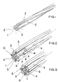
- FIG. 1 shows the core 1 of an optical fiber cable, which is structured according to the invention and, as a structure, has grooves or grooves 2 for receiving electrical wires that serve for the power supply.
- the core 1 of the aerial cable is formed, for example, by an aluminum profile wire.
- wires 3 are stored, the z. B. made of aluminum, aluminum alloy (Aldrey) or aluminum-coated steel (Stalum). The wires 3 are fixed by the grooves 2.
- the core 1, the wires 3 and the wires 4 of the second layer form chambers 5, into which the optical fibers 6 (hollow / loose tubes) are inserted.
- the diameter of the fiber optic wires 6 and the wires 3 of the first layer and the diameter of the core 1 and the depth and the fillet of the core 1 are matched to one another so that in the finished state the circumference formed by the wires 3 of the first layer is not touching the fiber optic wires 6 or only slightly fixing.
- the wires 3 of the first layer and thus also the grooves 2 of the core 1 are designed spirally with a lay length ratio of 6 to 12.
- the wires 4 of the second layer located above the first layer as well as the wires (7), optionally further layers (FIGS. 6 and 7), are each applied in the opposite direction to the wires of the layer located below.
- the lay length ratio of the second layer or other layers is based on DIN 41200 and is of the order of 10 to 15.
- the core 1 forms the wires 3 of the first layer and the wires 4 of the second layer secure stable Chambers 6 for the fiber optic wires 7.
- the first layer consists of four electrical wires 3.
- the arrangements of FIGS. 2 and 3 differ from one another only in that, in the arrangement of FIG. 2, parts of the fiber optic wires 6 and of the electrical wires 3 are omitted to clarify the arrangement Make fillets 2 visible.
- FIGS. 6 and 7 show an additional third layer with the wires 8.
- the wires of the individual layers can have different diameters.
Landscapes
- Physics & Mathematics (AREA)
- General Physics & Mathematics (AREA)
- Optics & Photonics (AREA)
- Communication Cables (AREA)
- Glass Compositions (AREA)
- Non-Insulated Conductors (AREA)
- Ropes Or Cables (AREA)
Description
- LWL-Kabel werden beispielsweise als Luftkabel für die Elektrizitätsversorgung verwendet. LWL ist die Abkürzung für Lichtwellenleiter. Im speziellen Fall eines LWL-Erdseilluftkabels dienen die Lichtwellenleiter als Erdseil.
- Es gibt seit langer Zeit Luftkabel mit metallischer Armierung (Erdseil-Luftkabel) mit Cu-Leitern. Davon wurden LWL-Luftkabel abgeleitet, indem die Cu-Leiter durch LWL-Adern ersetzt wurden. Der Kern solcher Luftkabel besteht somit aus einer LWL-Seele mit einem mehr oder weniger dicken PE-Mantel. Dieser Kern hat einen Durchmesser von 6 bis 10 mm. Über dem Kern werden eine oder mehrere Lagen Drähte (rund oder segmentiert) verseilt. Die zugkraftaufnehmenden Stahl- oder aluminiumummantelten Stahldrähte (Stalum) sind in der äußersten oder zweiten Lage von außen angeordnet, um einen sicheren Kraftschluß zur Spiralarmatur zu gewährleisten. Der Nachteil solcher Luftkabel besteht darin, daß im Inneren des Luftkabels für die LWL-Seele 30 bis 80 mm² Querschnitt leitungsbezogen nutzlos verschwendet werden und infolgedessen die Kabel 3 bis 7 mm dicker sind als Leiterseile mit dem gleichen tragenden/leitenden Querschnitt.
- Bekannt ist bereits eine flexible Starkstromleitung mit auf einen sternförmigen Kernstrang aufgeseilten Adern (DE-OS 32 24 597), die zusätzlich optische Übertragungselemente enthält. Diese sind im Innern der Schutzleiter angeordnet, welche sich in den Zwickeln zwischen den Energieadern befinden. Eingebettet sind Energieadern und die LWL-Adern enthaltenden Schutzleiter in der Masse des Innenmantels.
- Bei einem gattungsgemäßen Luftkabel (EP-A-146 757) hat man auch schon die optischen Elemente, nämlich einzelne Fasern oder Faserbündel in Nuten eines Kernstranges eingelegt, dieser Kernstrang ist jedoch von einem zusätzlichen metallischen Schutzrohr umgeben, auf das die erste Lage der Einzeldrähte des Luftkabels aufgeseilt sind.
- Der Erfindung liegt die Aufgabe zugrunde, die Durchmesserzunahme durch den nur übertragungstechnisch relevanten LWL-Teil so gering wie möglich zu halten und die Fasern der LWL-Adern sicher vor Umgebungseinflüssen wie Zug und Druck zu schützen. Diese Aufgabe wird bei einem LWL-Kabel mit einem Kern, LWL-Adern und elektrischen Leitern nach der Erfindung durch das Kennzeichen des Anspruchs 1 gelöst.
- Die verschiebungsfreie Anordnung der Elemente der ersten Lage auf dem Umfang ist gleichbedeutend damit, daß die Elemente der dem Kern benachbarten Lage senkrecht zur Kabelachse verschiebungsfrei angeordnet sind.
- Die Erfindung gewährleistet eine sichere Befestigung der Luftkabel an Trag- und Abspannmasten mittels Spiralarmaturen, d. h. den Stahlanteil möglichst weit nach außen zu bringen. Außerdem ermöglicht die Erfindung eine möglichst gleiche Lösung für Luftkabel mit 2 bis 12 LWL sowie eine sichere Muffenmontage, d. h. ein einfaches Trennen des oder der LWL-Teile vom Seil.
- Geht man davon aus, daß bei einem LWL-Kabel nach der Erfindung für je maximal 3 Fasern eine LWL-Ader von 2 mm Durchmesser ausreichend ist, dann beträgt die erforderliche Querschnittszunahme für ein 12-faseriges Luftkabel z. B. 12,5 mm². Bei einem leitungstechnisch erforderlichen Querschnitt von z. B. 150 mm² bedeutet das eine Querschnittsvergrößerung von 8 % gegenüber den bisher bekannten Luftkabeln von 20 - 52 %, also eine Durchmesserzunahme von 4 % gegenüber 10 - 23 %. Bei einem Seilquerschnitt von 300 mm² (Al/St 265/35) sind es sogar nur noch 2 % Durchmesserzunahme. Das heißt, ein Luftkabel hätte gegenüber dem vergleichbaren Seil einen Durchmesser von 20,4 mm gegenüber 20,0 mm. Der geschilderte Vorteil wird bei der Erfindung dadurch erreicht, daß Leitungsseilelemente - wie Runddrähte und Profildrähte - die Lagefixierung und den Schutz der LWL-Adern übernehmen.
- Die Erfindung wird im folgenden an Ausführungsbeispielen erläutert.
- Die Figur 1 zeigt den Kern 1 eines LWL-Kabels, der nach der Erfindung strukturiert ist und als Struktur Hohlkehlen bzw. Nuten 2 zur Aufnahme von elektrischen Drähten aufweist, die der Stromversorgung dienen. Den Kern 1 des Luftkabels bildet beispielsweise ein Profildraht aus Aluminium. In die Nuten 2 werden als erste Lage gemäß der Figur 2 Drähte 3 eingelagert, die z. B. aus Aluminium, Aluminiumlegierung (Aldrey) oder aluminiumummanteltem Stahl (Stalum) bestehen. Die Drähte 3 werden durch die Nuten 2 fixiert.
- Durch den Kern 1, die Drähte 3 sowie durch die Drähte 4 der zweiten Lage (Figuren 4 und 5) werden Kammern 5 gebildet, in die LWL-Adern 6 (Hohl/Bündeladern) eingelegt werden. Die Durchmesser der LWL-Adern 6 und der Drähte 3 der ersten Lage sowie der Durchmesser des Kernes 1 und die Tiefe sowie die Kehlung des Kerns 1 sind so aufeinander abgestimmt, daß im fertigen Zustand der Umkreis, der durch die Drähte 3 der ersten Lage gebildet wird, die LWL-Adern 6 nicht bzw. nur leicht fixierend berührt. Um die Faserbeweglichkeit über den erforderlichen Stauch- und Dehnungsbereich zu gewährleisten und gleichzeitig eine Flexibilität dieser inneren Seele zu ermöglichen, sind die Drähte 3 der ersten Lage und damit auch die Nuten 2 des Kernes 1 spiralig mit einem Schlaglängenverhältnis von 6 bis 12 ausgeführt.
- Die Drähte 4 der über der ersten Lage befindlichen zweiten Lage sowie die Drähte (7) gegebenenfalls weiterer Lagen (Figuren 6 und 7) werden jeweils in Gegenrichtung zu den Drähten der darunter befindlichen Lage aufgebracht. Das Schlaglängenverhältnis der zweiten Lage bzw. weiterer Lagen richtet sich nach DIN 41200 und liegt in der Größenordnung von 10 bis 15. Im Ausführungsbeispiel der Figuren 4 und 5 bilden der Kern 1 die Drähte 3 der ersten Lage und die Drähte 4 der zweiten Lage sichere stabile Kammern 6 für die LWL-Adern 7.
- Im Ausführungsbeispiel besteht die erste Lage aus vier elektrischen Drähten 3. Die Anordnungen der Figuren 2 und 3 unterscheiden sich lediglich dadurch voneinander, daß bei der Anordnung der Figur 2 zur Verdeutlichung Teile der LWL-Adern 6 sowie der elektrischen Drähte 3 weggelassen sind, um die Hohlkehlen 2 sichtbar zu machen.
- Die Figuren 6 und 7 zeigen noch eine zusätzliche dritte Lage mit den Drähten 8. Die Drähte der einzelnen Lagen können unterschiedliche Durchmesser haben.
Claims (2)
- Elektrisches Luftkabel mit einer ersten Lage auf einem Kernprofil (1) aufgeseilter Leiter (3) und mit im Verseilverband der Leiter angeordneten Lichtwellenleiter-Adern (6), dadurch gekennzeichnet, daß zur verschiebungsfreien Lagerung der auf das Kernprofil (1) aufgeseilten Leiter (3) in Umfangsrichtung dieses an seiner äußeren Umfangsfläche wendelförmig entlang der Kabelachse verlaufende Hohlkehlen (2) zur Aufnahme der Leiter (3) aufweist, daß die in benachbarten Hohlkehlen (2) festgelegten Leiter (3) mit den Leitern (4) einer zweiten, anschließenden Lage und mit einer von Leitern freien Oberfläche des Kernprofils (1) längs der Kabelachse verlaufende Kammern bilden, in denen die Lichtwellenleiter-Adern (6) aufgenommen sind.
- Luftkabel nach Anspruch 1, dadurch gekennzeichnet, daß die Leiter der zweiten Lage gegenüber der ersten, auf dem Kernstrang aufliegenden Lage eine entgegengesetzte Schlagrichtung zur Bildung der die LWL-Adern aufnehmenden Kammern aufweisen.
Applications Claiming Priority (2)
| Application Number | Priority Date | Filing Date | Title |
|---|---|---|---|
| DE3836706A DE3836706A1 (de) | 1988-10-28 | 1988-10-28 | Lwl-kabel |
| DE3836706 | 1988-10-28 |
Publications (3)
| Publication Number | Publication Date |
|---|---|
| EP0365762A2 EP0365762A2 (de) | 1990-05-02 |
| EP0365762A3 EP0365762A3 (de) | 1991-05-08 |
| EP0365762B1 true EP0365762B1 (de) | 1994-05-04 |
Family
ID=6366081
Family Applications (1)
| Application Number | Title | Priority Date | Filing Date |
|---|---|---|---|
| EP89113758A Expired - Lifetime EP0365762B1 (de) | 1988-10-28 | 1989-07-26 | Lichtwellenleiterkabel |
Country Status (6)
| Country | Link |
|---|---|
| EP (1) | EP0365762B1 (de) |
| AT (1) | ATE105421T1 (de) |
| DE (2) | DE3836706A1 (de) |
| DK (1) | DK170901B1 (de) |
| ES (1) | ES2052833T3 (de) |
| FI (1) | FI100745B (de) |
Families Citing this family (1)
| Publication number | Priority date | Publication date | Assignee | Title |
|---|---|---|---|---|
| NO175119C (no) * | 1992-02-06 | 1994-08-31 | Alcatel Stk As | Fiberoptisk kabel |
Family Cites Families (6)
| Publication number | Priority date | Publication date | Assignee | Title |
|---|---|---|---|---|
| DE2604766C3 (de) * | 1976-02-07 | 1981-12-24 | Kabel- und Metallwerke Gutehoffnungshütte AG, 3000 Hannover | Phasenseil für Starkstrom-Freileitungsnetze zur gleichzeitigen Energie- und Informationsübertragung |
| DE3205616C2 (de) * | 1982-02-17 | 1983-12-08 | Siemens AG, 1000 Berlin und 8000 München | Freileitungsseil mit Lichtleiter zur Nachrichtenübertragung |
| DE3224597A1 (de) * | 1982-06-29 | 1983-12-29 | Siemens AG, 1000 Berlin und 8000 München | Flexible starkstromleitung mit verseilten adern |
| GB2133206B (en) * | 1982-12-15 | 1986-06-04 | Standard Telephones Cables Ltd | Cable manufacture |
| JPS60105114A (ja) * | 1983-11-11 | 1985-06-10 | 住友電気工業株式会社 | 光フアイバ複合架空地線 |
| FR2563042B1 (fr) * | 1984-04-17 | 1986-07-25 | Electricite De France | Cable de transmission d'energie electrique et d'information |
-
1988
- 1988-10-28 DE DE3836706A patent/DE3836706A1/de not_active Withdrawn
-
1989
- 1989-07-26 DE DE58907609T patent/DE58907609D1/de not_active Expired - Fee Related
- 1989-07-26 AT AT8989113758T patent/ATE105421T1/de not_active IP Right Cessation
- 1989-07-26 ES ES89113758T patent/ES2052833T3/es not_active Expired - Lifetime
- 1989-07-26 EP EP89113758A patent/EP0365762B1/de not_active Expired - Lifetime
- 1989-08-09 DK DK391389A patent/DK170901B1/da not_active IP Right Cessation
- 1989-10-02 FI FI894646A patent/FI100745B/fi not_active IP Right Cessation
Also Published As
| Publication number | Publication date |
|---|---|
| EP0365762A3 (de) | 1991-05-08 |
| ES2052833T3 (es) | 1994-07-16 |
| DE3836706A1 (de) | 1990-05-03 |
| DE58907609D1 (de) | 1994-06-09 |
| FI894646A0 (fi) | 1989-10-02 |
| FI894646L (fi) | 1990-04-29 |
| DK391389D0 (da) | 1989-08-09 |
| DK170901B1 (da) | 1996-03-04 |
| DK391389A (da) | 1990-04-29 |
| ATE105421T1 (de) | 1994-05-15 |
| FI100745B (fi) | 1998-02-13 |
| EP0365762A2 (de) | 1990-05-02 |
Similar Documents
| Publication | Publication Date | Title |
|---|---|---|
| DE2820510C2 (de) | Elektrischer Freileiter | |
| EP0476438A2 (de) | Elektro-optisches Freileiterseil mit 24 und mehr Lichtwellenleitern | |
| DE60223167T2 (de) | Faseroptisches anschlusskabel | |
| DE19740726B4 (de) | Freileitungs-Lichtwellenleiterkabel | |
| DE2604766A1 (de) | Phasenseilkabel fuer starkstrom- freileitungsnetze zur gleichzeitigen energie- und informationsuebertragung | |
| DE19648473C2 (de) | Aufbau eines Freileitungs-Lichtwellenleiter-Verbundkabels unter Verwendung eines lose eingesetzten Röhrchens | |
| EP0443085B1 (de) | Elektrisches Freileiterseil mit integrierten Lichtwellenleitern | |
| DE2511019C2 (de) | Grundelement zum Aufbau optischer Kabel | |
| DE3023669C2 (de) | Selbsttragendes optisches Nachrichtenkabel | |
| EP0286804A2 (de) | Elektrisches Freileiterseil mit integrierten Lichtwellenleitern | |
| EP0433565B1 (de) | Lichtwellenleiter-(LWL)-Endverschluss eines LWL-Phasenseils | |
| DE29512268U1 (de) | Vorrichtung zur Verbindung von zwei elektrischen Luftkabeln | |
| DE3538664C2 (de) | ||
| EP0365759B1 (de) | Lichtwellenleiterkabel | |
| EP0992826A2 (de) | Abspannbares Kabel zur Verlegung in einem Kanal- oder Rohrsystem | |
| DE29520915U1 (de) | Nachrichtenkabel | |
| DE3820730A1 (de) | Freileiter mit einer optischen nachrichtenleitung | |
| EP0365762A2 (de) | Lichtwellenleiterkabel | |
| DE19631820C1 (de) | Elektrisches Mehrleiterkabel | |
| EP1157296A1 (de) | Lichtwellenleiteranordnung | |
| DE4214039C2 (de) | Vorrichtung zum Aufteilen von Lichtwellenleitern eines optischen Kabels | |
| DE29518024U1 (de) | Nachrichtenkabel | |
| EP0416207B1 (de) | Lichtwellenleiterkabel | |
| EP0547323B1 (de) | LWL-Verbindungseinrichtung für eine Abzweigung und Verfahren zum Herstellen einer LWL-Verbindung an einer Abzweigung | |
| EP0666576B1 (de) | Energiekabel |
Legal Events
| Date | Code | Title | Description |
|---|---|---|---|
| PUAI | Public reference made under article 153(3) epc to a published international application that has entered the european phase |
Free format text: ORIGINAL CODE: 0009012 |
|
| AK | Designated contracting states |
Kind code of ref document: A2 Designated state(s): AT BE CH DE ES FR GB IT LI NL SE |
|
| PUAL | Search report despatched |
Free format text: ORIGINAL CODE: 0009013 |
|
| AK | Designated contracting states |
Kind code of ref document: A3 Designated state(s): AT BE CH DE ES FR GB IT LI NL SE |
|
| 17P | Request for examination filed |
Effective date: 19910716 |
|
| 17Q | First examination report despatched |
Effective date: 19930129 |
|
| RAP1 | Party data changed (applicant data changed or rights of an application transferred) |
Owner name: KABEL RHEYDT AKTIENGESELLSCHAFT |
|
| ITF | It: translation for a ep patent filed | ||
| GRAA | (expected) grant |
Free format text: ORIGINAL CODE: 0009210 |
|
| AK | Designated contracting states |
Kind code of ref document: B1 Designated state(s): AT BE CH DE ES FR GB IT LI NL SE |
|
| REF | Corresponds to: |
Ref document number: 105421 Country of ref document: AT Date of ref document: 19940515 Kind code of ref document: T |
|
| REF | Corresponds to: |
Ref document number: 58907609 Country of ref document: DE Date of ref document: 19940609 |
|
| GBT | Gb: translation of ep patent filed (gb section 77(6)(a)/1977) |
Effective date: 19940602 |
|
| REG | Reference to a national code |
Ref country code: ES Ref legal event code: FG2A Ref document number: 2052833 Country of ref document: ES Kind code of ref document: T3 |
|
| ET | Fr: translation filed | ||
| EAL | Se: european patent in force in sweden |
Ref document number: 89113758.0 |
|
| PLBE | No opposition filed within time limit |
Free format text: ORIGINAL CODE: 0009261 |
|
| STAA | Information on the status of an ep patent application or granted ep patent |
Free format text: STATUS: NO OPPOSITION FILED WITHIN TIME LIMIT |
|
| 26N | No opposition filed | ||
| PGFP | Annual fee paid to national office [announced via postgrant information from national office to epo] |
Ref country code: GB Payment date: 19990614 Year of fee payment: 11 |
|
| PGFP | Annual fee paid to national office [announced via postgrant information from national office to epo] |
Ref country code: FR Payment date: 19990616 Year of fee payment: 11 |
|
| PGFP | Annual fee paid to national office [announced via postgrant information from national office to epo] |
Ref country code: CH Payment date: 19990617 Year of fee payment: 11 |
|
| PGFP | Annual fee paid to national office [announced via postgrant information from national office to epo] |
Ref country code: SE Payment date: 19990622 Year of fee payment: 11 Ref country code: AT Payment date: 19990622 Year of fee payment: 11 |
|
| PGFP | Annual fee paid to national office [announced via postgrant information from national office to epo] |
Ref country code: NL Payment date: 19990624 Year of fee payment: 11 |
|
| PGFP | Annual fee paid to national office [announced via postgrant information from national office to epo] |
Ref country code: DE Payment date: 19990626 Year of fee payment: 11 |
|
| PGFP | Annual fee paid to national office [announced via postgrant information from national office to epo] |
Ref country code: BE Payment date: 19990706 Year of fee payment: 11 |
|
| PGFP | Annual fee paid to national office [announced via postgrant information from national office to epo] |
Ref country code: ES Payment date: 19990719 Year of fee payment: 11 |
|
| PG25 | Lapsed in a contracting state [announced via postgrant information from national office to epo] |
Ref country code: GB Free format text: LAPSE BECAUSE OF NON-PAYMENT OF DUE FEES Effective date: 20000726 Ref country code: AT Free format text: LAPSE BECAUSE OF NON-PAYMENT OF DUE FEES Effective date: 20000726 |
|
| PG25 | Lapsed in a contracting state [announced via postgrant information from national office to epo] |
Ref country code: SE Free format text: LAPSE BECAUSE OF NON-PAYMENT OF DUE FEES Effective date: 20000727 Ref country code: ES Free format text: LAPSE BECAUSE OF NON-PAYMENT OF DUE FEES Effective date: 20000727 |
|
| PG25 | Lapsed in a contracting state [announced via postgrant information from national office to epo] |
Ref country code: LI Free format text: LAPSE BECAUSE OF NON-PAYMENT OF DUE FEES Effective date: 20000731 Ref country code: CH Free format text: LAPSE BECAUSE OF NON-PAYMENT OF DUE FEES Effective date: 20000731 Ref country code: BE Free format text: LAPSE BECAUSE OF NON-PAYMENT OF DUE FEES Effective date: 20000731 |
|
| BERE | Be: lapsed |
Owner name: KABEL RHEYDT A.G. Effective date: 20000731 |
|
| PG25 | Lapsed in a contracting state [announced via postgrant information from national office to epo] |
Ref country code: NL Free format text: LAPSE BECAUSE OF NON-PAYMENT OF DUE FEES Effective date: 20010201 |
|
| REG | Reference to a national code |
Ref country code: CH Ref legal event code: PL |
|
| EUG | Se: european patent has lapsed |
Ref document number: 89113758.0 |
|
| GBPC | Gb: european patent ceased through non-payment of renewal fee |
Effective date: 20000726 |
|
| PG25 | Lapsed in a contracting state [announced via postgrant information from national office to epo] |
Ref country code: FR Free format text: LAPSE BECAUSE OF NON-PAYMENT OF DUE FEES Effective date: 20010330 |
|
| NLV4 | Nl: lapsed or anulled due to non-payment of the annual fee |
Effective date: 20010201 |
|
| REG | Reference to a national code |
Ref country code: FR Ref legal event code: ST |
|
| PG25 | Lapsed in a contracting state [announced via postgrant information from national office to epo] |
Ref country code: DE Free format text: LAPSE BECAUSE OF NON-PAYMENT OF DUE FEES Effective date: 20010501 |
|
| REG | Reference to a national code |
Ref country code: ES Ref legal event code: FD2A Effective date: 20020603 |
|
| PG25 | Lapsed in a contracting state [announced via postgrant information from national office to epo] |
Ref country code: IT Free format text: LAPSE BECAUSE OF NON-PAYMENT OF DUE FEES;WARNING: LAPSES OF ITALIAN PATENTS WITH EFFECTIVE DATE BEFORE 2007 MAY HAVE OCCURRED AT ANY TIME BEFORE 2007. THE CORRECT EFFECTIVE DATE MAY BE DIFFERENT FROM THE ONE RECORDED. Effective date: 20050726 |