EP0365780B1 - Anschlussvorrichtung zum Schalten oder Trennen von Leitungswegen in Fernsprechvermittlungsanlagen - Google Patents
Anschlussvorrichtung zum Schalten oder Trennen von Leitungswegen in Fernsprechvermittlungsanlagen Download PDFInfo
- Publication number
- EP0365780B1 EP0365780B1 EP89115536A EP89115536A EP0365780B1 EP 0365780 B1 EP0365780 B1 EP 0365780B1 EP 89115536 A EP89115536 A EP 89115536A EP 89115536 A EP89115536 A EP 89115536A EP 0365780 B1 EP0365780 B1 EP 0365780B1
- Authority
- EP
- European Patent Office
- Prior art keywords
- connection
- line
- switching
- contact
- disconnecting
- Prior art date
- Legal status (The legal status is an assumption and is not a legal conclusion. Google has not performed a legal analysis and makes no representation as to the accuracy of the status listed.)
- Expired - Lifetime
Links
- 238000000926 separation method Methods 0.000 description 25
- 238000010586 diagram Methods 0.000 description 6
- 230000001681 protective effect Effects 0.000 description 5
- 239000004020 conductor Substances 0.000 description 4
- 238000012360 testing method Methods 0.000 description 4
- 238000000034 method Methods 0.000 description 3
- 238000013016 damping Methods 0.000 description 2
- 238000009413 insulation Methods 0.000 description 2
- 238000006073 displacement reaction Methods 0.000 description 1
- 238000009434 installation Methods 0.000 description 1
- 238000002955 isolation Methods 0.000 description 1
Images


Classifications
-
- H—ELECTRICITY
- H04—ELECTRIC COMMUNICATION TECHNIQUE
- H04Q—SELECTING
- H04Q1/00—Details of selecting apparatus or arrangements
- H04Q1/02—Constructional details
- H04Q1/14—Distribution frames
- H04Q1/142—Terminal blocks for distribution frames
-
- H—ELECTRICITY
- H05—ELECTRIC TECHNIQUES NOT OTHERWISE PROVIDED FOR
- H05K—PRINTED CIRCUITS; CASINGS OR CONSTRUCTIONAL DETAILS OF ELECTRIC APPARATUS; MANUFACTURE OF ASSEMBLAGES OF ELECTRICAL COMPONENTS
- H05K1/00—Printed circuits
- H05K1/02—Details
- H05K1/0286—Programmable, customizable or modifiable circuits
Definitions
- the invention relates to a terminal block for switching or separating line paths in telephone exchanges according to the preamble of claim 1.
- connection device of this type for a main distributor is previously known from DE-PS 25 18 832.
- the terminal block of the connecting device consists of a plastic body in which several pairs of contacts are inserted. These pairs of contacts are extended on the undersides and directed towards each other in such a way that separation points are formed between the contacts.
- An incoming and an outgoing line wire of a line path is connected to a pair of contacts, which can be separated via the separation point.
- a total of four connection contacts or two contact pairs are required to connect a line path consisting of a wire and b wire. Routing lines are preferably connected on one side of the connection strip and subscriber lines or switching lines are connected on the other side of the connection strip, in accordance with the use of the connection strip on the exchange or subscriber side of a main distributor.
- connection device has the disadvantage that special switching functions can only be carried out with great effort. So switching from a first line path to a second line path is only possible by means of a further connection device in which the Lines for the second route must be reconnected. This is often not possible for reasons of space, since the existing connection devices already occupy most of the distributor. For the first route, the connection device with a comparatively low connection capacity must first be replaced by a connection device with a higher connection capacity, re-routed and rewired on the exchange side. This creates the space required for the installation of connection devices for the second line path with marshalling and cable connections for, for example, a new digital switching system.
- the isolating point on the first connection device for the first line path must be opened by means of the isolating plug and the isolating point on the second connecting device for the second line path must be opened by pulling the isolating plug. Due to the local distance of the two connection devices, the switchover can only be carried out by two people on call, which creates a considerable uncertainty factor in the operation, which can lead to incorrect switching.
- the connection devices for the first line route including routing and switching line, are dismantled again, as a result of which a large part of the distributor becomes free again and initially remains unused.
- new connection devices are installed, routed and wired in this free space; the previously used devices including their routing and cabling are removed. This switching process is very complex, in particular due to the cabling and testing work.
- Another disadvantage is that if there is only one separation point, it is only accessible for one switching purpose, i.e. that with e.g. inserted damping or protective plug no more test plug can be inserted.
- the elements plugged into the separation point cover the connection contacts to such an extent that it is not possible to wire the contacts with lines.
- the object of the invention is therefore to provide a terminal block of the generic type which enables various switching functions, in particular the switching from one line path to another line path in the simplest and most economical way.
- the connecting device according to the invention is first installed in a free place to replace the old connecting device previously used. For the first route, the switching and routing lines are connected to the connection contacts. With the old connection device that is no longer required, the lines are removed. The old connection device is then dismantled. A new connection device is placed in its place again, and new switching lines and routing lines are connected for further first line routes. So each connection device is gradually connected until all old connection devices are replaced by new connection devices. Depending on the type of connection devices available, the connection capacity of the new connection devices is at least equal to or twice as high.
- the switching lines for the second route are e.g. to a digital switching system.
- the additional second disconnection points are opened using a disconnect plug.
- a new routing and a related check of the routing route is no longer necessary here.
- a disconnect plug is inserted at the first disconnection points of the first line path and the disconnect plug of the additional second disconnection points is removed for the second line path.
- This isolating plug is in turn inserted into the isolating points of a further first line path of another terminal block. This can be done very quickly, easily and safely by only one person because of the local proximity of the separation points for the first and second route.
- only the exchange-side lines of the first line path are removed.
- the pair of contacts that have become free with associated disconnection points can be used again in the same way for later switchovers or by closing the first disconnection points for parallel connections (double contacting) or by opening the second disconnection points for equivalent circuits. In order to There is no need for any further device changes in the event of further switchover measures, as well as the associated new routing and checking of the routing lines.
- the arrangement according to claim 1 causes the separation points to be spatially separated from the connection contacts. As a result, it is easily possible to switch the connection contacts on and off even when the plugs are inserted in the disconnection points, without the plugs having to be obstructed or removed.
- the cable routing within the terminal strip means that no additional component is required as a wire guide element.
- the thickness of the terminal block is not increased despite the wire guide.
- adapters of the same thickness can be snapped onto the upper longitudinal side of the terminal block for three-wire (a, b, c-wire) switching lines, which have connection contacts for the c-wires.
- the connecting contacts are connected to isolating contacts, the isolating point of which lies in one plane with the a-, b-isolating point of the terminal block and thus forms a complete a-, b-, c-isolating point.
- the arrangement according to claim 8 enables the separation points to be connected in series by the presence of two separation points, with appropriate line routing on the printed circuit board. This makes it possible to carry out two different switching functions at the same time, for example inserting a damping or protective plug in one disconnection point and using the other disconnection point for disconnection plugs or test cords.
- the arrangement according to claim 9 enables a separation point to be connected in series between three pairs of contacts, a pair of contacts for connecting the incoming line and a pair of contacts for connecting the outgoing line.
- the third contact pair arranged between these two contact pairs can be occupied by a further line, which is optionally connected in parallel to the incoming and outgoing line via two disconnection points or by only opening one or the other separation point to only one of the two lines.
- the c-wire is guided to the adapter through a line channel formed by the receiving trough and the terminal block.
- Adapters can be snapped onto the lower side of the terminal strip, two (a, b) or three (a, b, c) adapters each having connecting contacts with disconnecting or switching contact points, in order to be able to use special cables (connecting lines, announcement service, Earth bases) to connect and tap. These can be removed after the changeover if they are not required, which further reduces the dimensions of the connecting device.
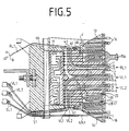
- the terminal block 20 of the connection device is formed from a rectangular, disk-shaped plastic housing 29 and serves to receive terminal contacts 1 to 6 and isolating contacts 21 to 28, which are used in the interior of the plastic housing 29.
- the six connection contacts 1 to 6 or the three contact pairs consist of metallic insulation displacement contacts for connecting insulated a and b cable wires of the switching, shunting and subscriber lines VL1, VL2, RL1, TL1.
- the isolating contacts 21 to 28 consist of metallic, strip-shaped elements, two isolating contacts 21 to 28 each being bent at their upper ends and directed towards one another and forming an isolating point 7, 8, 10, 11 at the point of contact.
- six connecting contacts 1 to 6 or three contact pairs and eight isolating contacts or four isolating points 7, 8, 10, 11 are provided in the terminal block 20.
- the connection contacts 1 to 6 are arranged between the four separation points 7, 8, 10, 11, the separation contacts 21 to 28 and the connection contacts 1 to 6 being aligned one behind the other in one plane.
- strip-shaped extensions 30 are provided which have hooks 31 bent at 90 ° at their ends.
- hooks 31 protrude into bores 19 of a printed circuit board 17 arranged in the rear area of the terminal block 20.
- the printed circuit board 17 has conductor tracks 18 which connect the bores 19 and thus the isolating contacts 21 to 28 to the connection contacts 1 to 6.
- various connection options between the isolating contacts 21 to 28 and the connecting contacts 1 to 6 are possible, as will be explained in more detail later.
- the disk-shaped housing 29 of the terminal block 20 has an upper and a lower longitudinal side 32,33 and a front and a rear narrow side 34,35.
- On the front narrow side 35 two retaining ribs 36 are provided for each connection contact 1 to 6, which serve to fix the cable wire to be connected.
- an insulating rib 37 is formed between the holding ribs 36, behind which the cut wire end of the connected cable core is sunk, by the electrically necessary insulation distance between two cut ends of the cable that are directed towards one another with the smallest space requirement to guarantee.
- a line routing channel 9 is provided in each case in the terminal block 20 between the connection contacts 1, 2, 3, 4, 5, 6 of a contact pair.
- a total of three guide channels 9 are arranged in the terminal block 20 for the six connection contacts 1 to 6, each of which has an inlet opening 43 and an outlet opening 44.
- the middle cable duct 9 has two inlet openings 43.
- the inlet openings 43 of the cable duct 9 are arranged on the long sides 32, 33 and the outlet openings 44 between the contact pairs on the front narrow side 35.
- the cable routing channels 9 are deflected within the terminal block 20 by approximately 90 °, so that the guide channels 9 are curved.
- the guide channel 9 runs for the upper contact pair 1, 2 from the upper long side 32, for the lower contact pair 5, 6 from the lower long side 33 and for the middle contact pair 3, 4 from the lower and upper long side 32, 33 to the front Narrow side 35.
- the lines VL1, VL2, TL1, RL1 are thus inserted from the upper or lower longitudinal side 32, 33 into the guide channels 9 of the terminal block 20 and brought up to the connection contacts 1 to 6, to which they are connected by means of a tool, not shown become.
- T-shaped guide elements 40 are provided on both longitudinal sides 32, 33 of the terminal block 20, at the ends of which a latching hook 41 directed towards the rear narrow side 34 is arranged.
- the latching hook 41 has a further latching element 42 on its upper side.
- the plastic bodies of the adapters 13 have T-shaped grooves 45 on the undersides and a holding tab 46 arranged at the rear end of the adapter 13, 14 with a receiving opening 47.
- the T-shaped groove 45 is opened to fasten and hold the adapter 13, 14 the T-shaped guide element 40 inserted until the locking element 42 of the terminal block 20 engages in the receiving opening 47 of the retaining tab 46.
- the two adapters 13, 14 can subsequently be attached to the longitudinal sides 32, 33 of the terminal block 20 in a mirror-inverted manner, and can be unlocked and removed by lifting the retaining tab 46.
- connection contacts 16 are arranged in the adapter 13, 14, between which a separation point 12 or a switching point 70 is arranged.
- the isolating point 12 and the switching point 70 are formed via two isolating or switching contacts 48, 49, which are each connected in one piece to the connecting contacts 16.
- T-shaped guide elements 50 for further additional elements, not shown, are also provided on the upper sides of the adapters 13, 14.
- Retaining ribs 36 are also provided on the front of the adapters 13, 14 in the region of the connecting contacts 16 and receiving openings 38 as access for the disconnection or switching point 12, 70.
- connection contacts 16 and the isolating contacts arranged in the adapter 13, 14 are also removed.
- Switching points 12, 70 are arranged in one level with the connecting contacts 1 to 6 and separating points 7, 8, 10, 11 arranged in the terminal strip 20.
- the adapters 13, 14 each have a rectilinear guide channel 65 with an outlet opening 71 ending between the connection contacts and an inlet opening 63 arranged on the rear side 64.
- connection device consisting of a plurality of connection strips 20 and a receiving trough 51 is preferably used in distribution frames.
- 1 shows a fastening rail 61 belonging to the distribution frame and the connection device for the horizontal switching side of a distribution frame.
- Several terminal strips 20 are inserted tightly into the receptacle 51.
- the receptacle 51 consists of a U-shaped plastic body, the open side of which is directed towards the front 39 of the distributor frame and on the upper and lower inner sides 53 of which a receptacle groove 52 formed by ribs 56 extends to the rear bottom side 67 of the receptacle 51 and is formed by a rib 56 is arranged.
- the receiving grooves 52 are used to guide and hold the terminal strips 20 and have inlet openings 43 which are aligned with the inlet openings 43 of the terminal block 20.
- the rear narrow side 34 of the connecting bar 20 and the inner bottom side 67 of the receiving trough 51 with two side surfaces form a conduit channel 66 for the c-wire of the switching line VL1 or other special lines SL1 the inlet and outlet openings 68, 69 provided on the outer sides 57 of the receiving trough 51.
- the c-wire is inserted from below into the inlet opening 68 and guided in the conduit 66 to the outlet opening 69 on the upper outside 57 of the receiving trough 51.
- the marshalling, switching and subscriber line RL1, VL1, VL2, TL1 are guided on the upper and lower outer sides 57 of the receiving trough 51 between guide ribs 54.
- the c-wire On the upper outside 57 of the receiving trough 51, the c-wire is brought up to the adapter 13 and there through the guide channel 65 to the connection contact 16 to which the c-wire is connected by means of a tool, not shown.
- a T-groove is provided, which serves to receive a mounting rail 55, which is provided at certain intervals with screw bolts 60 which are fixedly connected to the mounting rail 55 via a welded connection or riveted connection.
- the mounting rail 55 receives a plurality of receiving troughs 51 with connection strips 20 and is thus assembled as a whole on a mounting rail 61 of a distribution frame (not shown).
- the fastening rail 61 has corresponding perforations 62 through which the screw bolts 60 of the mounting rail 55 are inserted.
- the receptacle 51 can be manufactured in different lengths, with the corresponding number of connection strips 20 used.
- FIGS. 4, 5 and 6 illustrate the switching process using the first exemplary embodiment of the terminal block 20, the two upper contact pairs 1, 2 for connecting a routing line RL1 consisting of a and b wires and the contact pairs 3, 4 and 5, 6 serve to connect one switching line VL1, VL2 each.
- the upper connection contact 1, 3, 5 is used to connect the b wires and the lower connection contact 2, 4, 6 is used to connect the a wire.
- the upper disconnection points 10, 11 serve to separate the routing line RL1 connected to the connection contacts 1, 2 from the first switching line VL1 connected to the contact pair 3, 4.
- the lower isolating point 7, 8 arranged in the terminal block 20 serves to separate the routing line RL1 and the switching line VL2 connected to the contact pair 5, 6.
- the corresponding connections between the connection contacts 1 to 6 and the isolating contacts 21 to 28 take place via the conductor tracks 18 arranged on the printed circuit board 17.
- connection contact 1 for connecting the jumper line RL1 is connected to the isolating contact 21 of the isolating point 11 and to the isolating contact 25 of the isolating point 7.
- the isolating contact 22 of the isolating point 11 is connected to the connecting contact 3 for connecting the first switching line VL1 and the isolating contact 26 of the isolating point 7 is connected to the connecting contact 5 for connecting the second switching line VL2.
- connection contact 2 for connecting the jumper cable RL1 is connected to the isolating contact 23 of the isolating point 10 and to the isolating contact 27 of the isolating point 8.
- the isolating contact 24 of the isolating point 10 is connected to the connecting contact 4 for connecting the first switching line VL1 and the isolating contact 28 of the isolating point 8 is connected to the connecting contact 6 for connecting the second switching line VL2.
- the contact pair 1, 2 for connecting the shunting line RL1 via a disconnection point 10, 11 to the contact pair 3, 4 for connecting the first switching line VL1 (first line path) and via one further separation point 7,8 connected to the contact pair 5,6 for connecting the second switching line VL2 (second line path).
- FIG. 4 shows the terminal block 20 in which the jumper line RL1 is connected to the terminal contacts 1, 2.
- the routing line RL1 is brought in from the rear mounting side 59, guided between the guide ribs 54 of the upper outer side 57 and inserted into the inlet opening 43 of the upper outer side 57 and the upper longitudinal side 33 of the terminal block 20 and through the guide channel 9 to the contact pair 1, 2 introduced and connected.
- the a and b wires of the switching line VL1 are connected to the contact pair 3, 4 and the switching line VL2 to the contact pair 5, 6.
- Both switching lines VL1, VL2 are brought up from the lower outside 57 and inserted into the inlet opening 43 of the lower outside 57 and the lower longitudinal side 34 of the terminal block 20 into the guide channels 9.
- Adapters 13, 14 are snapped onto both longitudinal sides 32, 33 of the terminal block 20.
- the c-wires of the first switching line VL1 are connected to the connection contact 16.
- special lines SL1 for e.g. Announcement services or earth lines connected.
- the switching line VL1 is separated from the switching line RL1.
- the double isolating plug 15 is then pulled out of the isolating points 7, 8, as a result of which the switching line VL1 is connected to the routing line RL1, as shown in FIG. 5.
- the switching line VL1 which is no longer required, is then disconnected from the connection contacts 3 and 4 and pulled out of the guide channel 9.
- the adapter 13 is removed since the switching line VL2 only consists of the a and b wires.
- the adapter 14 can be removed when not required.
- the isolating plug 15 can also be removed after the switching line VL1 has been disconnected.
- the now free connection contacts 3 and 4 can be used for parallel connections or later switchovers.
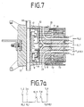
- FIG. 7 A second exemplary embodiment is shown in FIG. 7, in which the connecting bar 20 is arranged on the vertical or horizontal side of the distributor frame.
- the electrical connections via the conductor tracks 18 between the connection contacts 1 to 6 and the isolating contacts 21 to 28 are shown schematically in this connection block 20 in a circuit diagram (FIG. 7a).
- connection contact 1 for a second jumper line RL2 is connected to the connection contact 3 for a first jumper line RL1 and the isolating contact 21 of the disconnection point 11.
- the isolating contact 22 of the isolating point 11 is connected to the isolating contact 25 of the isolating point 7, the isolating contact 26 of which is connected to the connection contact 5 for a subscriber line TL1 or switching line VL1.
- connection contact 2 for the second jumper line RL2 is connected to the connection contact 4 for the first jumper line RL1 and the isolating contact 23 of the disconnection point 10.
- the isolating contact 24 of the isolating point 10 is connected to the isolating contact 27 of the isolating point 8, the isolating contact 28 of which is connected to the connection contact 6 for the subscriber line TL1 or switching line VL1.
- the contact pair 5, 6 for connecting the subscriber lines TL1 or switching line VL1 are assigned two contact pairs 1, 2, 3, 4 for two routing lines RL1, RL2 via two disconnection points 7, 8, 10, 11.
- Test and protective plugs can thus be inserted in the cable path at the same time, since there are two separation points 7, 8, 10, 11.
- an earth adapter 72 is snapped onto the lower longitudinal side 32 of the terminal block 20 and has an earth busbar 73.
- the protective plug is inserted into the separation point 7, 8 and in the earth adapter 73, whereby an earth connection is made from the separation points 7, 8 to the earth busbar 73 in the event of an overvoltage.
- connection for the a-core is arranged at the bottom and for the b-core at the top, corresponding to the a-core separation point 7, 10 and the b-core separation point 8, 11.
- FIG. 8 shows a third exemplary embodiment, in which the terminal block 20 is used for the connection for subscriber lines TL1, switching lines VL1 and routing lines RL1.
- the connections between the connecting contacts 1 to 6 and the isolating contacts 21 to 28 also take place here via the conductor tracks 18 of the printed circuit board 17 and are shown schematically in a circuit diagram in FIG. 8a.
- connection contact 1 for the switching line VL1 is connected to the disconnection contact 21 of the disconnection point 11, whose disconnection contact 22 is connected to the connection contact 5 for the jumper line RL1.
- connection contact 5 is connected to the disconnection contact 25 of the disconnection point 7, the disconnection contact 26 of which is connected to the connection contact 3 for the subscriber line TL1.
- connection contact 2 for the switching line VL1 is connected to the isolating contact 23 of the disconnection point 10, the isolating contact 24 of which is connected to the connection contact 6 for the routing line RL1.
- the connection contact 6 is connected to the isolating contact 27 of the isolating point 8, the isolating contact 28 of which is connected to the connecting contact 4 for the subscriber line 1.
- the contact pair 3, 4 for connecting the subscriber line TL1 via the first disconnection point 7, 8 is a contact pair 5, 6 for connecting the shunt line RL1 and the contact pair 5, 6 via a second disconnection point 10, 11 a contact pair 1, 2 Connection of the switching line VL1 assigned.
- connections between at least two terminal strips 20 arranged next to one another take place either via a connection from printed circuit board to printed circuit board 17 or via a connecting plug which connects the separation points 7, 8 or 10, 11 of a first connection strip 20 to the separation points 7, 8 or 10, 11 connects at least one second terminal block 20 or the separating points 7, 8, 10, 11 or 10, 11, 12 to two or three adapters 14 via connecting cords.
- the connections for example, multiply the connection capacity.
Landscapes
- Engineering & Computer Science (AREA)
- Computer Networks & Wireless Communication (AREA)
- Structure Of Telephone Exchanges (AREA)
- Interface Circuits In Exchanges (AREA)
- Exchange Systems With Centralized Control (AREA)
Description
- Die Erfindung bezieht sich auf eine Anschlußleiste zum Schalten oder Trennen von Leitungswegen in Fernsprechvermittlungsanlagen gemäß dem Oberbegriff des Anspruches 1.
- Eine Anschlußvorrichtung dieser Art für einen Hauptverteiler ist aus der DE-PS 25 18 832 vorbekannt. Die Anschlußleiste der Anschlußvorrichtung besteht aus einem Kunststoffkörper, in dem mehrere Kontaktpaare eingelegt sind. Diese Kontaktpaare sind an den Unterseiten derart verlängert und zueinander gerichtet, daß zwischen den Kontakten Trennstellen gebildet sind. An je einem Kontaktpaar wird eine ankommende und eine abgehende Leitungsader eines Leitungsweges angeschlossen, der über die Trennstelle auftrennbar ist. Zum Anschluß eines aus a-Ader und b-Ader bestehenden Leitungsweges sind insgesamt vier Anschlußkontakte bzw. zwei Kontaktpaare notwendig. Auf der einen Seite der Anschlußleiste werden vorzugsweise Rangierleitungen und auf der anderen Seite der Anschlußleiste Teilnehmerleitungen oder Vermittlungsleitungen angeschlossen, entsprechend der Verwendung der Anschlußleiste auf der Vermittlungs- oder Teilnehmerseite eines Hauptverteilers.
- Eine derartige Anschlußvorrichtung hat jedoch den Nachteil, daß spezielle Schaltfunktionen nur sehr aufwendig durchführbar sind. So ist ein Umschalten von einem ersten Leitungsweg auf einen zweiten Leitungsweg nur mittels einer weiteren Anschlußvorrichtung möglich, bei der die Leitungen für den zweiten Leitungsweg neu angeschlossen werden müssen. Dieses ist oft aus Platzgründen nicht möglich, da die vorhandenen Anschlußvorrichtungen bereits den größten Teil des Verteilers belegen. Es muß zunächst für den ersten Leitungsweg die Anschlußvorrichtung mit einer vergleichsweisen geringen Anschlußkapazität gegen eine Anschlußvorrichtung mit einer höheren Anschlußkapazität ersetzt, neu rangiert und vermittlungsseitig neu verkabelt werden. Hierdurch entsteht der benötigte Platz für die Installation von Anschlußvorrichtungen für den zweiten Leitungsweg mit Rangier- und Kabelanschlüssen für z.B. eine neue digitale Vermittlungsanlage. Diese muß nochmals neu rangiert und durchgeprüft werden, wobei vor der Beschaltung mit den Rangierleitungen die Trennstelle mittels Trennstecker geöffnet werden muß. Beim Umschalten muß an der ersten Anschlußvorrichtung für den ersten Leitungsweg die Trennstelle mittels Trennstecker geöffnet und an der zweiten Anschlußvorrichtung für den zweiten Leitungsweg die Trennstelle durch Ziehen des Trennsteckers geöffnet werden. Die Umschaltung kann wegen der örtlichen Entfernung der beiden Anschlußvorrichtungen nur durch zwei Personen auf Zuruf erfolgen, wodurch ein erheblicher Unsicherheitsfaktor bei der Bedienung entsteht, der zu Fehlschaltungen führen kann. Nach erfolgter Umschaltung werden die Anschlußvorrichtungen für den ersten Leitungsweg einschließlich Rangierung und Vermittlungsleitung wieder demontiert, wodurch ein großer Teil des Verteilers wieder frei wird und zunächst ungenutzt bleibt. Bei erneuten Umschaltungen werden an diesem freien Platz wieder neue Anschlußvorrichtungen installiert, rangiert und verkabelt; die vorher genutzten Geräte einschließlich ihrer Rangierungen und Verkabelungen werden entfernt. Dieser Umschaltvorgang ist sehr aufwendig, insbesondere durch die Verkabelungs- und Prüfungsarbeiten.
- Weiterhin nachteilig ist, daß bei nur einer vorhandenen Trennstelle diese nur für einen Schaltzweck zugänglich ist, d.h. daß bei einem z.B. eingesteckten Dämpfungs- oder Schutzstecker kein Prüfsteker mehr eingesteckt werden kann. Außerdem decken die in die Trennstelle gesteckten Elemente die Anschlußkontakte soweit ab, daß ein Beschalten der Kontakte mit Leitungen nicht möglich ist.
- Aus der Druckschrift EP-A-0 243 296 ist eine Verteilereinrichtung mit zwei Kontaktpaaren und zwei Trennstellen bekannt. Das eine Kontaktpaar dient hierbei zum Anschluß der Vermittlungsleitungen, während das andere Kontaktpaar zum Anschluß der Teilnehmerleitung dient. Zwischen den Kontakten ist jeweils eine Trennstelle vorgesehen. Nachteilig hierbei ist, daß nur dieser starre Aufbau zwischen Teilnehmerleitung und Vermittlungsleitung verwendet werden kann. Darüber hinaus besteht der Nachteil, daß Vermittlungsleitung und Teilnehmerleitung auf verschiedenen Seiten (Vorder- und Rückseite bzw. Anschalteseite und Manipulierseite) angeordnet sind, so daß die Bedienperson um das Gestell herumlaufen muß. Die Anordnung ist auch als Wandgestell nicht einsetzbar.
- Aufgabe der Erfindung ist es daher, eine Anschlußleiste der gattungsgemäßen Art zu schaffen, die verschiedene Schaltfunktionen, insbesondere das Umschalten von einem Leitungsweg auf einen anderen Leitungsweg auf einfachste und wirtschaftlichste Art ermöglicht.
- Die Lösung dieser Aufgabe ergibt sich aus den kennzeichnenden Merkmalen des Patentanspruches 1.
- Weitere vorteilhafte Ausgestaltungen der Erfindung ergeben sich aus den Unteransprüchen. Gemäß einer bevorzugten Ausführung nach Anspruch 7 wird zum Austausch der alten bisher verwendeten Anschlußvorrichtung die erfindungsgemäße Anschlußvorrichtung zuerst an einem freien Platz montiert. Für den ersten Leitungsweg werden die Vermittlungs- und Rangierleitungen an die Anschlußkontakte angeschlossen. Bei der alten, nicht mehr benötigten Anschlußvorrichtung werden die Leitungen entfernt. Die alte Anschlußvorrichtung wird danach demontiert. An ihren Platz wird wieder eine neue Anschlußvorrichtung gesetzt, und für weitere erste Leitungswege werden neue Vermittlungsleitungen und Rangierleitungen angeschlossen. So wird nach und nach jede Anschlußvorrichtung beschaltet, bis alle alten Anschlußvorrichtungen gegen neue Anschlußvorrichtungen ausgetauscht sind. Je nach Art der vorhandenen Anschlußvorrichtungen ist die Anschlußkapazität der neuen Anschlußvorrichtungen mindestens gleich bis doppelt so hoch.
- Danach werden die Vermittlungsleitungen für den zweiten Leitungsweg z.B. zu einer digitalen Vermittlunsanlage gelegt. Vor dem Anschließen an das zusätzliche Kontaktpaar werden die zusätzlichen zweiten Trennstellen mittels Trennstecker geöffnet.
- Eine erneute Rangierung und eine damit verbundene Prüfung des Rangierleitungsweges ist hier nicht mehr notwendig. Zum Zeitpunkt der Umschaltung wird an den ersten Trennstellen des ersten Leitungsweges ein Trennstecker gesteckt und der Trennstecker der zusätzlichen zweiten Trennstellen für den zweiten Leitungsweg gezogen. Dieser Trennstecker wird wiederum in die Trennstellen eines weiteren ersten Leitungsweges einer anderen Anschlußleiste gesteckt. Dies kann wegen der örtlichen Nähe der Trennstellen für den ersten und zweiten Leitungsweg sehr schnell, einfach und sicher von nur einer Person durchgeführt werden. Nach erfolgter Umschaltung werden lediglich die vermittlungsseitigen Leitungen des ersten Leitungsweges entfernt. Das freigewordene Kontaktpaar mit zugehörigen Trennstellen kann in gleicher Weise wieder für spätere Umschaltungen oder durch Schließen der ersten Trennstellen für parallele Anschaltungen (Doppelkontaktierung) oder weiterhin durch Öffnen der zweiten Trennstellen für Ersatzschaltungen verwendet werden. Damit entfällt jeglicher weiterer Gerätewechsel bei weiteren Umschaltmaßnahmen sowie das damit verbundene neue Rangieren und Prüfen der Rangierleitungen.
- Die Anordnung gemäß Anspruch 1 bewirkt, daß die Trennstellen räumlich von den Anschlußkontakten getrennt sind. Dadurch ist es problemlos möglich, auch bei in den Trennstellen eingesteckten Steckern die Anschlußkontakte zu be- und entschalten, ohne daß die Stecker behindern oder entfernt werden müßten.
- Ein weiterer Vorteil ergibt sich aus dem Anspruch 2. Durch die Leitungsführung innerhalb der Anschlußleiste wird kein zusätzliches Bauelement als Drahtführungselement benötigt. Die Dicke der Anschlußleiste wird trotz Drahtführung nicht erweitert.
- Gemäß Anspruch 4 können für dreiadrig (a-,b-,c-Ader) geführte Vermittlungsleitungen an der oberen Längsseite der Anschlußleiste Adapter gleicher Dicke aufgerastet werden, die Anschlußkontakte für die c-Adern aufweisen. Die Anschlußkontakte sind mit Trennkontakten verbunden, deren Trennstelle in einer Ebene mit der a-,b-Trennstelle der Anschlußleiste liegt und somit eine vollständige a-, b-, c-Trennstelle bildet.
- Die Anordnung gemäß Anspruch 8 ermöglicht durch das Vorhandensein von zwei Trennstellen, bei entsprechender Leitungsführung auf der Leiterplatte, die Trennstellen in Reihe zu schalten. Dadurch ist es möglich, zwei unterschiedliche Schaltfunktionen gleichzeitig auszuführen, z.B. in eine Trennstelle einen Dämpfungs- oder Schutzstecker zu stecken und die andere Trennstelle für Trennstecker oder Prüfschnüre zu verwenden.
- Die Anordnung gemäß Anspruch 9 ermöglicht, daß zwischen drei Kontaktpaaren jeweils eine Trennstelle in Reihe geschaltet ist, wobei ein Kontaktpaar zum Anschluß der ankommenden und ein Kontaktpaar zum Anschluß für die abgehende Leitung vorgesehen ist. Das zwischen diesen beiden Kontaktpaaren angeordnete dritte Kontaktpaar kann mit einer weiteren Leitung belegt werden, die wahlweise über beide Trennstellen parallel mit der ankommenden und abgehenden Leitung oder durch Auftrennen der einen oder anderen Trennstelle nur mit einer der beiden Leitungen verbunden ist.
- Gemäß Anspruch 10 wird die c-Ader durch einen von der Aufnahmewanne und der Anschlußleiste gebildeten Leitungskanal zum Adapter geführt. Nach erfolgter Umschaltung und dem Entfernen der a-, b- und c-Leitungen des Vermittlungskabels für den ersten Leitungsweg können die Adapter wieder entfernt und somit die Abmessungen der Anschlußvorrichtung verkleinert werden.
- An der unteren Seite der Anschlußleiste können gemäß Anspruch 11 Adapter aufgerastet werden, wobei jeweils zwei (a,b) oder drei (a,b,c) Adapter Anschlußkontakte mit Trenn- oder Schaltkontaktstellen aufweisen, um hieran eventuell benötigte Sonderleitungen (Verbindungsleitungen, Ansagedienst, Erdstützpunkte) anschließen und abgreifen zu können. Diese können nach erfolgter Umschaltung bei Nichtbedarf wieder entfernt werden, wodurch die Abmessungen der Anschlußvorrichtung weiter verkleinert werden.
- Die Erfindung ist nachfolgend anhand eines in den Zeichnungen dargestellten Ausführungsbeispieles einer Anschlußvorrichtung näher erläutert. Es zeigt:
- Fig. 1
- eine perspektivische Darstellung mehrerer in eine Aufnahmewanne eingesetzter Anschlußleisten,
- Fig. 2
- eine perspektivische Darstellung einer Anschlußleiste mit zwei Adaptern,
- Fig. 3
- eine perspektivische Darstellung der Anschlußkontakte und der Trennstellen,
- Figuren 4, 5 und 6
- Querschnitte durch die Anschlußleiste zur Darstellung des Umschaltvorganges in einem ersten Ausführungsbeispiel,
- Fig. 4a
- ein der Fig. 4 zugeordnetes Schaltbild,
- Fig. 7
- einen Querschnitt durch die Anschlußleiste in einem zweiten Ausführungsbeispiel und
- Fig. 7a
- ein der Fig. 7 zugeordnetes Schaltbild,
- Fig. 8
- einen Querschnitt durch die Anschlußleiste in einem dritten Ausführungsbeispiel.
- Fig. 8a
- ein der Fig. 8 zugeordnetes Schaltbild.
- Die Anschlußleiste 20 der Anschlußvorrichtung ist aus einem rechteckigen, scheibenförmigen Kunststoffgehäuse 29 gebildet und dient zur Aufnahme von Anschlußkontakten 1 bis 6 und von Trennkontakten 21 bis 28, die im Inneren des Kunststoffgehäuses 29 eingesetzt sind. Die sechs Anschlußkontakte 1 bis 6 bzw. die drei Kontaktpaare bestehen aus metallischen Schneid-Klemm-Kontakten zum Anschluß von isolierten a- und b-Kabeladern der Vermittlungs-, Rangier- und Teilnehmerleitungen VL1, VL2, RL1, TL1.
- Die Trennkontakte 21 bis 28 bestehen aus metallischen, streifenförmigen Elementen, wobei jeweils zwei Trennkontakte 21 bis 28 an ihren oberen Enden abgebogen und zueinandergerichtet sind und am Berührungspunkt eine Trennstelle 7,8;10,11 bilden. In der Anschlußleiste 20 sind im Ausführungsbeispiel sechs Anschlußkontakte 1 bis 6 bzw. drei Kontaktpaare und acht Trennkontakte bzw. vier Trennstellen 7,8;10,11 vorgesehen. Die Anschlußkontakte 1 bis 6 sind zwischen den vier Trennstellen 7,8;10,11 angeordnet, wobei die Trennkontakte 21 bis 28 und die Anschlußkontakte 1 bis 6 hintereinander in einer Ebene ausgerichtet sind. An den unteren Enden der Anschlußkontakte 1 bis 6 und der Trennkontakte 21 bis 28 sind streifenförmige Verlängerungen 30 vorgesehen, die an ihren Enden um 90° abgebogene Haken 31 aufweisen. Diese Haken 31 ragen in Bohrungen 19 einer im hinteren Bereich der Anschlußleiste 20 angeordneten Leiterplatte 17 hinein. Die Leiterplatte 17 weist Leiterbahnen 18 auf, die die Bohrungen 19 und somit die Trennkontakte 21 bis 28 mit den Anschlußkontakten 1 bis 6 verbindet. Entsprechend der gewünschten Schaltfunktion sind verschiedene Verbindungsmöglichkeiten zwischen den Trennkontakten 21 bis 28 und den Anschlußkontakten 1 bis 6 möglich, wie später noch näher erläutert werden wird.
- Das scheibenförmige Gehäuse 29 der Anschlußleiste 20 besitzt eine obere und eine untere Längsseite 32,33 und eine vordere und eine hintere Schmalseite 34,35. An der vorderen Schmalseite 35 sind für jeden Anschlußkontakt 1 bis 6 zwei Halterippen 36 vorgesehen, die zur Fixierung der anzuschließenden Kabelader dienen. Zwischen einem Kontaktpaar 1,2;3,4;5,6 ist jeweils zwischen den Halterippen 36 eine Isolierrippe 37 ausgebildet, hinter der das abgeschnittene Drahtende der angeschlossenen Kabelader versenkt wird, um den elektrisch notwendigen Isolationsabstand zweier zueinander gerichteter, abgeschnittener Leitungsenden bei geringstem Platzbedarf zu gewährleisten.
- Des weiteren sind an der vorderen Schmalseite 35 im Gehäuse 29 Aufnahmeöffnungen 38, z.B. für Trennstecker 15 vorgesehen, die als Zugang zu den Trennstellen 7,8;10,11 dienen. Zur Führung und Fixierung der Vermittlungs-, Rangier- und Teilnehmerleitungen VL1, VL2, RL1, TL1 ist zwischen den Anschlußkontakten 1,2;3,4;5,6 eines Kontaktpaares in der Anschlußleiste 20 jeweils ein Leitungsführungskanal 9 vorgesehen. Insgesamt sind für die sechs Anschlußkontakte 1 bis 6 drei Führungskanäle 9 in der Anschlußleiste 20 angeordnet, die jeweils eine Eintrittsöffnung 43 und eine Austrittsöffnung 44 besitzen. Der mittlere Leitungsführungskanal 9 besitzt zwei Eintrittsöffnungen 43. Die Eintrittsöffnungen 43 der Leitungsführungskanäle 9 sind an den Längsseiten 32,33 und die Austrittsöffnungen 44 zwischen den Kontaktpaaren an der vorderen Schmalseite 35 angeordnet. Die Leitungsführungskanäle 9 werden innerhalb der Anschlußleiste 20 um ca. 90° umgelenkt, so daß die Führungskanäle 9 bogenförmig gestaltet sind. Im Ausführungsbeispiel verläuft der Führungskanal 9 für das obere Kontaktpaar 1,2 von der oberen Längsseite 32, für das untere Kontaktpaar 5,6 von der unteren Längsseite 33 und für das mittlere Kontaktpaar 3,4 von der unteren und oberen Längsseite 32,33 zur vorderen Schmalseite 35. Die Leitungen VL1, VL2, TL1, RL1 werden somit von der oberen oder unteren Längsseite 32,33 in die Führungskanäle 9 der Anschlußleiste 20 eingeschoben und bis an die Anschlußkontakte 1 bis 6 herangeführt, an denen sie mittels eines nicht dargestellten Werkzeuges angeschlossen werden.
- An beiden Längsseiten 32,33 der Anschlußleiste 20 sind T-förmige Führungselemente 40 vorgesehen, an deren Enden ein zur hinteren Schmalseite 34 gerichteter Rasthaken 41 angeordnet ist. Der Rasthaken 41 weist an seiner Oberseite ein weiteres Rastelement 42 auf. Über das T-förmige Führungselement 40 und das Rastelement 42 können somit an den Längsseiten 32,33 zusätzlich Adapter 13,14 zum Anschluß von c-Adern der Vermittlungsleitung VL1 oder Sonderleitungen SL1 aufgeschoben und aufgerastet werden. Die Kunststoffkörper der Adapter 13 besitzen hierzu an den Unterseiten T-förmige Nuten 45 und eine am hinteren Ende des Adapters 13,14 angeordnete Haltelasche 46 mit einer Aufnahmeöffnung 47. Zur Befestigung und Halterung des Adapters 13,14 wird die T-förmige Nut 45 auf das T-förmige Führungselement 40 eingeschoben, bis das Rastelement 42 der Anschlußleiste 20 in die Aufnahmeöffnung 47 der Haltelasche 46 eingreift. Beide Adapter 13,14 können nachträglich spiegelbildlich zueinander gerichtet an den Längsseiten 32,33 der Anschlußleiste 20 befestigt und durch Anheben der Haltelasche 46 entrastet und entfernt werden.
- Im Adapter 13,14 sind, wie insbesondere Fig. 3 zeigt, zwei Anschlußkontakte 16 angeordnet, zwischen denen eine Trennstelle 12 oder eine Schaltstelle 70 angeordnet ist. Die Trennstelle 12 und die Schaltstelle 70 werden über zwei Trenn- bzw. Schaltkontakte 48,49 gebildet, die jeweils mit den Anschlußkontakten 16 einstückig verbunden sind.
- An den Oberseiten der Adapter 13,14 sind darüber hinaus T-förmige Führungselemente 50 für weitere nicht dargestellte Zusatzelemente vorgesehen. An der Vorderseite der Adapter 13,14 sind ebenfalls Halterippen 36 im Bereich der Anschlußkontakte 16 und Aufnahmeöffnungen 38 als Zugang für die Trenn- bzw. Schaltstelle 12,70 vorgesehen.
- Nach dem Aufrasten der Adapter 13,14 auf die Anschlußleiste 20 sind auch die im Adapter 13,14 angeordneten Anschlußkontakte 16 und Trenn- bwz. Schaltstellen 12,70 in einer Ebene mit den in der Anschlußleiste 20 angeordneten Anschlußkontakten 1 bis 6 und Trennstellen 7,8;10,11 angeordnet.
- Zur Führung der Kabeladern besitzen die Adapter 13,14 je einen geradlinig verlaufenden Führungskanal 65 mit einer zwischen den Anschlußkontakten endenden Austrittsöffnung 71 und einer an der hinteren Seite 64 angeordneten Eintrittsöffnung 63.
- Die aus mehreren Anschlußleisten 20 und einer Aufnahmewanne 51 bestehende Anschlußvorrichtung wird vorzugsweise in Verteilergestellen eingesetzt. In Fig. 1 sind eine zum Verteilergestell gehörenden Befestigungsschiene 61 und die Anschlußvorrichtung für die waagerechte Vermittlungsseite eines Verteilergestelles dargestellt. Mehrere Anschlußleisten 20 sind hierbei dicht an dicht in die Aufnahmewanne 51 eingesetzt. Die Aufnahmewanne 51 besteht aus einem U-förmigen Kunststoffkörper, dessen offene Seite zur Vorderseite 39 des Verteilergestelles gerichtet ist und an dessen oberen und unteren Innenseiten 53 jeweils für eine Anschlußleiste 20 eine zur hinteren Bodenseite 67 der Aufnahmewanne 51 verlaufende, durch Rippen 56 gebildete Aufnahmenut 52 angeordnet ist. Die Aufnahmenuten 52 dienen zur Führung und Halterung der Anschlußleisten 20 und weisen Eintrittsöffnungen 43 auf, die mit den Eintrittsöffnungen 43 der Anschlußleiste 20 fluchten.
- Nach dem Einstecken der Anschlußleiste 20 in die Aufnahmenut 52 der Aufnahmewanne 51 bilden die hintere Schmalseite 34 der Anschlußleiste 20 und die innere Bodenseite 67 der Aufnahmewanne 51 mit zwei Seitenflächen einen Leitungskanal 66 für die c-Ader der Vermittlungsleitung VL1 oder andere Sonderleitungen SL1, mit an den Außenseiten 57 der Aufnahmewanne 51 vorgesehenen Eintritts- und Austrittsöffnungen 68,69. Die c-Ader wird von unten in die Eintrittsöffnung 68 eingeschoben und im Leitungskanal 66 bis zur Austrittsöffnung 69 an der oberen Außenseite 57 der Aufnahmewanne 51 geführt. Die Rangier-, Vermittlungs- und Teilnehmerleitung RL1,VL1,VL2,TL1 werden an den oberen und unteren Außenseiten 57 der Aufnahmewanne 51 zwischen Führungsrippen 54 geführt.
- An der oberen Außenseite 57 der Aufnahmewanne 51 wird die c-Ader bis zum Adapter 13 und dort durch den Führungskanal 65 an den Anschlußkontakt 16 herangeführt, an dem die c-Ader mittels eines nicht dargestellten Werkzeuges angeschlossen wird.
- An den freien Enden der oberen und unteren Außenseiten 57 der U-förmigen Aufnahmewanne 51 sind längsverlaufende Rastnuten 58 vorgesehen, in die die Rasthaken 41 der Anschlußleisten 20 nach dem Einstecken der Anschlußleisten 20 in die Aufnahmewanne 51 einrasten. An der rückwärtigen Montageseite 59 der Aufnahmewanne 51 ist eine T-Nut vorgesehen, die zur Aufnahme einer Montageschiene 55 dient, die in bestimmten Abständen mit Schraubbolzen 60 versehen ist, die fest mit der Montageschiene 55 über eine Schweißverbindung bzw. Nietverbindung verbunden sind. Die Montageschiene 55 nimmt mehrere Aufnahmewannen 51 mit Anschlußleisten 20 auf und wird somit als Ganzes an eine Befestigungsschiene 61 eines nicht dargestellten Verteilergestells montiert. Die Befestigungsschiene 61 weist entsprechende Lochungen 62 auf, durch die die Schraubbolzen 60 der Montageschiene 55 eingesteckt sind. Die Aufnahmewanne 51 kann in verschiedenen Längen hergestellt werden, mit der entsprechenden Anzahl von eingesetzten Anschlußleisten 20.
- In den Figuren 4,5 und 6 wird anhand des ersten Ausführungsbeispiels der Anschlußleiste 20 der Umschaltvorgang dargestellt, wobei die beiden oberen Kontaktpaare 1,2 zum Anschluß einer aus a- und b-Ader bestehenden Rangierleitung RL1 und die Kontaktpaare 3,4 und 5,6 zum Anschluß von je einer Vermittlungsleitung VL1,VL2 dienen. Bei jedem Anschlußkontaktpaar 1,2;3,4;5,6 dient der obere Anschlußkontakt 1,3,5 zum Anschluß der b-Adern und der untere Anschlußkontakt 2,4,6 zum Anschluß der a-Ader. Die oberen Trennstellen 10,11 dienen zur Trennung der an den Anschlußkontakten 1,2 angeschlossenen Rangierleitung RL1 von der am Kontaktpaar 3,4 angeschlossenen ersten Vermittlungsleitung VL1. Die in der Anschlußleiste 20 angeordnete untere Trennstelle 7,8 dient zur Trennung der Rangierleitung RL1 und der am Kontaktpaaar 5,6 angeschlossenen Vermittlungsleitung VL2. Die entsprechenden Verbindungen zwischen den Anschlußkontakten 1 bis 6 und den Trennkontakten 21 bis 28 erfolgen über die auf der Leiterplattte 17 angeordneten Leiterbahnen 18.
- Wie schematisch in Fig. 4a in einem Schaltbild dargestellt, bestehen folgende Verbindungen:
- Für die b-Ader ist der Anschlußkontakt 1 zum Anschluß der Rangierleitung RL1 mit dem Trennkontakt 21 der Trennstelle 11 und mit dem Trennkontakt 25 der Trennstelle 7 verbunden. Der Trennkontakt 22 der Trennstelle 11 ist mit dem Anschlußkontakt 3 zum Anschluß der ersten Vermittlungsleitung VL1 und der Trennkontakt 26 der Trennstelle 7 mit dem Anschlußkontakt 5 zum Anschluß der zweiten Vermittlungsleitung VL2 verbunden.
- Für die a-Ader ist der Anschlußkontakt 2 zum Anschluß der Rangierleitung RL1 mit dem Trennkontakt 23 der Trennstelle 10 und mit dem Trennkontakt 27 der Trennstelle 8 verbunden. Der Trennkontakt 24 der Trennstelle 10 ist mit dem Anschlußkontakt 4 zum Anschluß der ersten Vermittlungsleitung VL1 und der Trennkontakt 28 der Trennstelle 8 mit dem Anschlußkontakt 6 zum Anschluß der zweiten Vermittlungsleitung VL2 verbunden.
- Durch diese Verbindungen ist das Kontaktpaar 1,2 zum Anschluß der Rangierleitung RL1 über eine Trennstelle 10,11 mit dem Kontaktpaar 3,4 zum Anschluß der ersten Vermittlungsleitung VL1 (erster Leitungsweg) und über eine weitere Trennstelle 7,8 mit dem Kontaktpaar 5,6 zum Anschluß der zweiten Vermittlungsleitung VL2 (zweiter Leitungsweg) verbunden.
- Somit kann eine Umschaltung von einem ersten Leitungsweg (Rangierleitung/erste Vermittlungsleitung) auf einen zweiten Leitungsweg (Rangierleitung/zweite Vermittlungsleitung) hergestellt werden, deren Funktionsablauf in den Figuren 4,5 und 6 näher dargestellt ist.
- In Figur 4 ist die Anschlußleiste 20 dargestellt, bei der an den Anschlußkontakten 1,2 die Rangierleitung RL1 angeschlossen ist. Die Rangierleitung RL1 wird hierbei von der rückwärtigen Montageseite 59 herangeführt, zwischen den Führungsrippen 54 der oberen Außenseite 57 geführt und in die Eintrittsöffnung 43 der oberen Außenseite 57 und der oberen Längsseite 33 der Anschlußleiste 20 eingeführt und durch den Führungskanal 9 bis an das Kontaktpaar 1,2 herangeführt und angeschlossen. Am Kontaktpaar 3,4 sind die a- und b-Adern der Vermittlungsleitung VL1 und an das Kontaktpaar 5,6 die Vermittlungsleitung VL2 angeschlossen. Beide Vermittlungsleitungen VL1,VL2 werden von der unteren Außenseite 57 herangeführt und in die Eintrittsöffnung 43 der unteren Außenseite 57 und der unteren Längsseite 34 der Anschlußleiste 20 in die Führungskanäle 9 eingeführt. An beiden Längsseiten 32,33 der Anschlußleiste 20 sind Adapter 13, 14 aufgerastet. Am an die obere Längsseite 32 aufgerasteten Adapter 13 sind am Anschlußkontakt 16 die c-Adern der ersten Vermittlungsleitung VL1 angeschlossen. An die an der unteren Längsseite 33 aufgerasteten Adapter 14 werden Sonderleitungen SL1 für z.B. Ansagedienste oder Erdleitungen angeschlossen.
- Zur Umschaltung des ersten Leitungsweges vom Kontaktpaar 1,2 zum Kontaktpaar 3,4 auf einen zweiten Leitungsweg vom Kontaktpaar 1,2 zum Kontaktpaar 5,6 muß vor Anschluß der Vermittlungsleitung VL2 ein Zweifach-Trennstecker 15 in die Trennstellen 7,8 eingesteckt werden, die Verbindung zwischen Rangierleitung RL1 und Vermittlungsleitung VL2 bleibt somit vorerst getrennt (Fig. 4). Als zweiter Schritt wird ein weiterer Zweifach-Trennstecker 15a in die Trennstellen 10,11 der Anschlußleiste 20 gesteckt, wodurch die Verbindung zwischen Rangierleitung RL1 und Vermittlungsleitung VL1 aufgetrennt ist (Fig. 5). Die am Adapter 13 angeschlossene c-Ader braucht nicht getrennt zu werden, da nur eine c-Ader angschlossen ist. Hierdurch ist die Vermittlungsleitung VL1 von der Rangierleitung RL1 getrennt. Der Zweifach-Trennstecker 15 wird danach aus den Trennstellen 7,8 herausgezogen, wodurch die Vermittlungsleitung VL1 mit der Rangierleitung RL1 verbunden ist, wie es in Fig. 5 dargestellt ist.
- Wie die Fig. 6 zeigt, wird danach die nun nicht mehr benötigte Vermittlungsleitung VL1 von den Anschlußkontakten 3 und 4 abgeklemmt und aus dem Führungskanal 9 herausgezogen. Der Adapter 13 wird entfernt, da die Vermittlungsleitung VL2 nur noch aus der a- und b-Ader besteht. Der Adapter 14 kann bei Nichtbedarf entfernt werden. Auch der Trennstecker 15 kann nach dem Abtrennen der Vermittlungsleitung VL1 gezogen werden. Die nun freien Anschlußkontakte 3 und 4 können für parallele Anschaltungen oder spätere weitere Umschaltungen genutzt werden.
- In der Figur 7 ist ein zweites Ausführungsbeispiel dargestellt, bei der die Anschlußleiste 20 auf der senkrechten oder waagerechten Seite des Verteilergestells angeordnet ist. Die elektrischen Verbindungen über die Leiterbahnen 18 zwischen den Anschlußkontakten 1 bis 6 und den Trennkontakten 21 bis 28 sind bei dieser Anschlußleiste 20 schematisch in einem Schaltbild dargestellt (Fig. 7a).
- Für die b-Adern ist der Anschlußkontakt 1 für eine zweite Rangierleitung RL2 mit dem Anschlußkontakt 3 für eine erste Rangierleitung RL1 und dem Trennkontakt 21 der Trennstelle 11 verbunden. Der Trennkontakt 22 der Trennstelle 11 ist mit dem Trennkontakt 25 der Trennstelle 7 verbunden, dessen Trennkontakt 26 mit dem Anschlußkontakt 5 für eine Teilnehmerleitung TL1 oder Vermittlungsleitung VL1 verbunden ist.
- Für die a-Adern ist der Anschlußkontakt 2 für die zweite Rangierleitung RL2 mit dem Anschlußkontakt 4 für die erste Rangierleitung RL1 und dem Trennkontakt 23 der Trennstelle 10 verbunden. Der Trennkontakt 24 der Trennstelle 10 ist mit dem Trennkontakt 27 der Trennstelle 8 verbunden, deren Trennkontakt 28 mit dem Anschlußkontakt 6 für die Teilnehmerleitung TL1 oder Vermittlungsleitung VL1 verbunden ist.
- Durch diese Verbindungen sind dem Kontaktpaar 5,6 zum Anschluß der Teilnehmerleitungen TL1 oder Vermittlungsleitung VL1 zwei Kontaktpaare 1,2;3,4 für zwei Rangierleitungen RL1, RL2 über zwei Trennstellen 7,8;10,11 zugeordnet. In dem Leitungsweg können somit gleichzeitig Test- und Schutzstecker eingesteckt werden, da zwei Trennstellen 7,8;10,11 vorhanden sind. Für den nicht dargestellten Schutzstecker wird an der unteren Längsseite 32 der Anschlußleiste 20 ein Erd-Adapter 72 aufgerastet, der eine Erd-Sammelschiene 73 aufweist. Der Schutzstecker wird in die Trennstelle 7,8 und in den Erd-Adapter 73 eingesteckt, wodurch eine Erdverbindung von den Trennstellen 7,8 zur Erd-Sammelschiene 73 im Überspannungsfall hergestellt ist.
- In vorteilhafter Weise ist der Anschluß für die a-Ader unten und für die b-Ader oben angeordnet, entsprechend der a-Ader-Trennstelle 7,10 und der b-Ader-Trennstelle 8,11.
- In Fig. 8 ist ein drittes Ausführungsbeispiel dargestellt, bei dem die Anschlußleiste 20 zum Anschluß für Teilnehmerleitungen TL1, Vermittlungsleitungen VL1 und Rangierleitungen RL1 dient. Die Verbindungen zwischen den Anschlußkontakten 1 bis 6 und den Trennkontakten 21 bis 28 erfolgen auch hier über die Leiterbahnen 18 der Leiterplatte 17 und sind in Fig. 8a schematisch in einem Schaltbild dargestellt.
- Für die b-Ader ist der Anschlußkontakt 1 für die Vermittlungsleitung VL1 mit dem Trennkontakt 21 der Trennstelle 11 verbunden, dessen Trennkontakt 22 mit dem Anschlußkontakt 5 für die Rangierleitung RL1 verbunden ist.
- Der Anschlußkontakt 5 ist mit dem Trennkontakt 25 der Trennstelle 7 verbunden, deren Trennkontakt 26 mit dem Anschlußkontakt 3 für die Teilnehmerleitung TL1 verbunden ist.
- Für die a-Ader ist der Anschlußkontakt 2 für die Vermittlungsleitung VL1 mit dem Trennkontakt 23 der Trennstelle 10 verbunden, deren Trennkontakt 24 mit dem Anschlußkontakt 6 für die Rangierleitung RL1 verbunden ist. Der Anschlußkontakt 6 ist mit dem Trennkontakt 27 der Trennstelle 8 verbunden, deren Trennkontakt 28 mit dem Anschlußkontakt 4 für die Teilnehmerleitung 1 verbunden ist.
- Durch diese Verbindungen ist dem Kontaktpaar 3,4 zum Anschluß der Teilnehmerleitung TL1 über die erste Trennstelle 7,8 ein Kontaktpaar 5,6 zum Anschluß der Rangierleitung RL1 und dem Kontaktpaar 5,6 über eine zweite Trennstelle 10,11 ein Kontaktpaar 1,2 zum Anschluß der Vermittlungsleitung VL1 zugeordnet.
- Weitere Verknüpfungen bzw. Verbindungen zwischen den Kontaktpaaren und den Trennstellen sind durch entsprechende Leiterplatten möglich. In einer nicht dargestellten Ausführung erfolgen die Verbindungen zwischen mindestens zwei nebeneinander angeordneten Anschlußleisten 20 entweder über eine Verbindung von Leiterplatte zu Leiterplatte 17 oder über einen Verbindungsstecker, der die Trennstellen 7,8 oder 10,11 einer ersten Anschlußleiste 20 mit den Trennstellen 7,8 oder 10,11 mindestens einer zweiten Anschlußleiste 20 oder die Trennstellen 7,8 oder 10,11 bzw. 10,11,12 mit zwei bzw. drei Adaptern 14 über Verbindungsschnüre verbindet. Durch die Verknüpfungen wird z.B. die Anschlußkapazität vervielfacht.
-

Claims (11)
- Anschlußvorrichtung zum Schalten oder Trennen von Leitungswegen in Fernsprechvermittlungsanlagen, bestehend aus einer Aufnahmewannanne (51) und aus mehreren von dieser aufgenommenen Anschlußleisten (20), die aus einem Gehäuse (29) mit einem Kontaktpaar zum Anschluß von Rangierleitungen und mit einem Kontaktpaar zum An schluß von Vermittlungs- oder Teilnehmerleitungen gebildet sind, wobei die Kontaktpaare über zwei Trennstellen verbunden sind,
dadurch gekennzeichnet,
daß innerhalb einer Ebene drei Kontaktpaare (1,2;3,4;5,6) und zwei Paare von Trennstellen (7,8;10,11) in einer Anschlußleiste (20) angeordnet sind, wobei die Kontaktpaare (1,2;3,4;5,6) mit den Trennstellen (7,8;10,11) entsprechend der gewünschten Schalt- und Umschaltfunktion über Leiterbahnen (18) verbunden sind, die auf einer in der Anschlußleiste (20) gelagerten Leiterplatte (17) aufgebracht sind. - Anschlußvorrichtung nach Anspruch 1,
dadurch gekennzeichnet, daß zwischen den Anschlußkontakten (1-6) der Kontaktpaare der Anschlußleiste (20) Leitungsführungskanäle (9) mit an deren Längs- und Schmalseiten (32,33,35) vorgesehenen Eintritts- und Austrittsöffnungen (43,44) angeordnet sind. - Anschlußvorrichtung nach Anspruch 1,
dadurch gekennzeichnet, daß ein mittlerer Leitungsführungskanal (9) zwei Eintrittsöffnungen (43) an den beiden Längsseiten (32,33) und eine Austrittsöffnung (44) an der vorderen Schmalseite (35) der Anschlußleiste (20) aufweist. - Anschlußvorrichtung nach Anspruch 1,
dadurch gekennzeichnet, daß an den Längsseiten (32,33) der Anschlußleiste (20) mindestens ein Adapter (13,14) mit zwei Anschlußkontakten (16) und einer Trennstelle (12) oder Schaltstelle (70) über Rast- und Führungselemente (40,42) aufsetzbar ist. - Anschlußvorrichtung nach den Ansprüchen 1 und 4,
dadurch gekennzeichnet, daß die Trennstelle (12) des Adapters (13) und die Trennstellen (10,11) der Anschlußleiste (20) eine in einer Ebene liegende Dreifach-Trennstelle (10,11,12) bilden. - Anschlußvorrichtung nach Anspruch 1,
dadurch gekennzeichnet, daß die Leiterbahnen (18) von mindestens zwei Anschlußleisten (20) miteinander über ein Verbindungselement elektrisch verbunden sind. - Abschlußvorrichtung nach Anspruch 1,
dadurch gekennzeichnet, daß das Kontaktpaar (1,2) zum Anschluß der Rangierleitungen (RL1) über die erste Trennstelle (7,8) mit dem Kontaktpaar (5,6) zum Anschluß einer zweiten Vermittlungsleitung (VL2) und daß das Kontaktpaar (1,2) über die zweite Trennstelle (10,11) mit dem Kontaktpaar (3,4) zum Anschluß einer ersten Vermittlungsleitung (VL1) verbunden ist. - Anschlußvorrichtung nach Anspruch 1,
dadurch gekennzeichnet, daß das Kontaktpaar (5,6) zum Anschluß der Teilnehmerleitung (TL1) oder der Vermittlungsleitung (VL1) über die erste Trennstelle (7,8) und über die zweite Trennstelle (10,11) mit dem Kontaktpaar (1,2) und dem Kontaktpaar (3,4) zum Anschluß von zwei Rangierleitungen (RL1,RL2) verbunden ist. - Anschlußvorrichtung nach Anspruch 1,
dadurch gekennzeichnet, daß das Kontaktpaar (3,4) zum Anschluß einer Teilnehmerleitung (TL1) über die erste Trennstelle (7,8) und die zweite Trennstelle (10,11) zu dem Kontaktpaar (1,2) zum Anschluß der Vermittlungsleitung (VL1) und zwischen den beiden Trennstellen (7,8;10,11) das Kontaktpaar (5,6) zum Anschluß der Rangierleitung (RL1) geschaltet ist. - Anschlußvorrichtung nach Anspruch 1,
dadurch gekennzeichnet, daß ein Leitungskanal (66) für die von der einen zur anderen Außenseite (57) der Aufnahmewanne (51) geführten Leitungen aus der hinteren Schmalseite (34) der Anschlußleiste (20) und aus einer inneren Bodenseite (67) mit zwei Seitenflächen einer U-förmigen Aufnahmewanne (51) gebildet ist, mit je einer Eintritts- und Austrittsöffnung (68,69) an den Außenseiten (57) der Aufnahmewanne (51). - Anschlußvorrichtung nach den Ansprüchen 1 und 4,
dadurch gekennzeichnet, daß die Trennstellen (12) oder die Schaltstellen (70) von mindestens zwei Adaptern (13,14) zweier Anschlußleisten (20) mindestens eine Zweifach-Trenn- oder -Schaltstelle bilden.
Applications Claiming Priority (2)
| Application Number | Priority Date | Filing Date | Title |
|---|---|---|---|
| DE3836668A DE3836668C1 (de) | 1988-10-25 | 1988-10-25 | |
| DE3836668 | 1988-10-25 |
Publications (3)
| Publication Number | Publication Date |
|---|---|
| EP0365780A2 EP0365780A2 (de) | 1990-05-02 |
| EP0365780A3 EP0365780A3 (de) | 1992-05-27 |
| EP0365780B1 true EP0365780B1 (de) | 1995-04-26 |
Family
ID=6366055
Family Applications (1)
| Application Number | Title | Priority Date | Filing Date |
|---|---|---|---|
| EP89115536A Expired - Lifetime EP0365780B1 (de) | 1988-10-25 | 1989-08-23 | Anschlussvorrichtung zum Schalten oder Trennen von Leitungswegen in Fernsprechvermittlungsanlagen |
Country Status (4)
| Country | Link |
|---|---|
| EP (1) | EP0365780B1 (de) |
| AT (1) | ATE121897T1 (de) |
| DE (2) | DE3836668C1 (de) |
| ES (1) | ES2071633T3 (de) |
Families Citing this family (7)
| Publication number | Priority date | Publication date | Assignee | Title |
|---|---|---|---|---|
| DE4042240C2 (de) * | 1990-12-31 | 1994-12-15 | Quante Ag | Anschlußmodul für eine Verteilereinrichtung, insbesondere für den Hauptverteiler von Fernmeldeeinrichtungen |
| US5312270A (en) * | 1992-08-25 | 1994-05-17 | The Siemon Company | Wiring block having detachable leg assemblies |
| DE19711128C1 (de) * | 1997-03-10 | 1998-07-30 | Krone Ag | Verteilerleiste für die Telekommunikations- und Datentechnik |
| EP0966844B1 (de) * | 1997-03-13 | 2001-10-24 | RXS Gesellschaft für Vermögensverwaltung mbH | Verteilereinrichtung mit blockartig aneinandergereihten verbindungsbauteilen |
| US6340317B1 (en) | 1998-11-20 | 2002-01-22 | International Connectors & Cable Corporation | Hinged wiring block |
| DE10029649C9 (de) | 2000-06-15 | 2008-02-07 | Adc Gmbh | Verteileranschlußmodul für die Telekommunikations- und Datentechnik |
| EP1455418A1 (de) * | 2003-03-03 | 2004-09-08 | 3M Innovative Properties Company | Telekommunikationsmodul |
Family Cites Families (6)
| Publication number | Priority date | Publication date | Assignee | Title |
|---|---|---|---|---|
| DE2518832C3 (de) * | 1975-04-28 | 1985-01-10 | Krone Gmbh, 1000 Berlin | Kontaktsegment für Trenn- und Anschlußleisten |
| FR2469020A1 (fr) * | 1979-10-31 | 1981-05-08 | Pouyet Expl Ets Henri | Tete de cable |
| DE3509523C3 (de) * | 1985-03-16 | 1996-07-04 | Quante Ag | Kabelabschlußeinheit |
| CA1263970A (en) * | 1985-07-15 | 1989-12-19 | American Telephone And Telegraph Company | Connecting block for digital system cross-connect frame |
| DE3614063C3 (de) * | 1986-04-23 | 1994-02-24 | Krone Ag | Verteilereinrichtung, insbesondere für den Hauptverteiler von Fernsprechanlagen |
| DE3629551A1 (de) * | 1986-08-30 | 1988-03-10 | Telefonbau & Normalzeit Gmbh | Anordnung fuer hauptverteiler |
-
1988
- 1988-10-25 DE DE3836668A patent/DE3836668C1/de not_active Expired - Lifetime
-
1989
- 1989-08-23 AT AT89115536T patent/ATE121897T1/de not_active IP Right Cessation
- 1989-08-23 DE DE58909196T patent/DE58909196D1/de not_active Expired - Fee Related
- 1989-08-23 ES ES89115536T patent/ES2071633T3/es not_active Expired - Lifetime
- 1989-08-23 EP EP89115536A patent/EP0365780B1/de not_active Expired - Lifetime
Also Published As
| Publication number | Publication date |
|---|---|
| EP0365780A3 (de) | 1992-05-27 |
| DE3836668C1 (de) | 1990-03-08 |
| ES2071633T3 (es) | 1995-07-01 |
| EP0365780A2 (de) | 1990-05-02 |
| ATE121897T1 (de) | 1995-05-15 |
| DE58909196D1 (de) | 1995-06-01 |
Similar Documents
| Publication | Publication Date | Title |
|---|---|---|
| DE3710896C2 (de) | ||
| DE19515923C2 (de) | Sammelschienen-Adapter | |
| EP0847106B1 (de) | Anschluss-, Trenn- oder Schaltleiste | |
| EP0521284A2 (de) | Reihenklemme mit Aufsteckmodul | |
| DE2715522A1 (de) | Trennbuchsenblock fuer ein fernmeldesystem | |
| EP0243296B1 (de) | Verteilereinrichtung, insbesondere für den Hauptverteiler von Fernsprechanlagen | |
| EP0766482A2 (de) | Verteilereinrichtung für die Telekommunikations- und Datentechnik | |
| EP0364658A2 (de) | Verteilereinrichtung, insbesondere für den Hauptverteiler von Fernsprechanlagen | |
| EP0365780B1 (de) | Anschlussvorrichtung zum Schalten oder Trennen von Leitungswegen in Fernsprechvermittlungsanlagen | |
| DE3879365T2 (de) | Klinkensteckermodul mit eingebauten lampen. | |
| DE4306349C1 (de) | Verteilereinrichtung, insbesondere für den Hauptverteiler von Fernsprech- und Datenleitungen | |
| EP0461454B1 (de) | Verteilereinrichtung | |
| DE3545186C2 (de) | ||
| EP0493740B1 (de) | Anschlussmodul für eine Verteilereinrichtung, insbesondere für den Hauptverteiler von Fernmeldeeinrichtungen | |
| DE3629551C2 (de) | ||
| DE19537529C1 (de) | Verteilerleiste für die Telekommunikations- und Datentechnik | |
| EP0667650A2 (de) | Modulares Anschlusssystem | |
| DE69612043T2 (de) | Schaltsystem mit Anschlussklemmenmodulen | |
| DE2443725A1 (de) | Verteilerleiste fuer elektrische anlagen, insbesondere fuer fernsprechanlagen | |
| DE3505617C1 (de) | Reihenklemmenanordnung | |
| DE2320895C2 (de) | Verteiler für Fernmelde-, insbesondere Fernsprechanlagen | |
| DE3919621C2 (de) | Anschlußverteilerleiste für ankommende und abgehende elektrische Leitungen | |
| DE861267C (de) | Hauptverteiler in Telefonzentralen | |
| DE2643046C3 (de) | Zwiscnenverteiler für Fernmeldevennittlungsanlagen | |
| DE4006549C1 (en) | Electrical connector strip for switching installation - has coupling rail in lower conductor plane separable at dividing point |
Legal Events
| Date | Code | Title | Description |
|---|---|---|---|
| PUAI | Public reference made under article 153(3) epc to a published international application that has entered the european phase |
Free format text: ORIGINAL CODE: 0009012 |
|
| AK | Designated contracting states |
Kind code of ref document: A2 Designated state(s): AT BE CH DE ES FR GB GR IT LI LU NL SE |
|
| PUAL | Search report despatched |
Free format text: ORIGINAL CODE: 0009013 |
|
| AK | Designated contracting states |
Kind code of ref document: A3 Designated state(s): AT BE CH DE ES FR GB GR IT LI LU NL SE |
|
| 17P | Request for examination filed |
Effective date: 19920515 |
|
| 17Q | First examination report despatched |
Effective date: 19940412 |
|
| GRAA | (expected) grant |
Free format text: ORIGINAL CODE: 0009210 |
|
| AK | Designated contracting states |
Kind code of ref document: B1 Designated state(s): AT BE CH DE ES FR GB GR IT LI LU NL SE |
|
| REF | Corresponds to: |
Ref document number: 121897 Country of ref document: AT Date of ref document: 19950515 Kind code of ref document: T |
|
| ITF | It: translation for a ep patent filed | ||
| REF | Corresponds to: |
Ref document number: 58909196 Country of ref document: DE Date of ref document: 19950601 |
|
| ET | Fr: translation filed | ||
| GBT | Gb: translation of ep patent filed (gb section 77(6)(a)/1977) |
Effective date: 19950517 |
|
| REG | Reference to a national code |
Ref country code: ES Ref legal event code: FG2A Ref document number: 2071633 Country of ref document: ES Kind code of ref document: T3 |
|
| REG | Reference to a national code |
Ref country code: GR Ref legal event code: FG4A Free format text: 3016135 |
|
| PLBE | No opposition filed within time limit |
Free format text: ORIGINAL CODE: 0009261 |
|
| STAA | Information on the status of an ep patent application or granted ep patent |
Free format text: STATUS: NO OPPOSITION FILED WITHIN TIME LIMIT |
|
| 26N | No opposition filed | ||
| PGFP | Annual fee paid to national office [announced via postgrant information from national office to epo] |
Ref country code: DE Payment date: 19970828 Year of fee payment: 9 |
|
| PGFP | Annual fee paid to national office [announced via postgrant information from national office to epo] |
Ref country code: GB Payment date: 19980729 Year of fee payment: 10 |
|
| PGFP | Annual fee paid to national office [announced via postgrant information from national office to epo] |
Ref country code: FR Payment date: 19980819 Year of fee payment: 10 |
|
| PGFP | Annual fee paid to national office [announced via postgrant information from national office to epo] |
Ref country code: SE Payment date: 19980824 Year of fee payment: 10 Ref country code: BE Payment date: 19980824 Year of fee payment: 10 |
|
| PGFP | Annual fee paid to national office [announced via postgrant information from national office to epo] |
Ref country code: LU Payment date: 19980825 Year of fee payment: 10 Ref country code: AT Payment date: 19980825 Year of fee payment: 10 |
|
| PGFP | Annual fee paid to national office [announced via postgrant information from national office to epo] |
Ref country code: CH Payment date: 19980826 Year of fee payment: 10 |
|
| PGFP | Annual fee paid to national office [announced via postgrant information from national office to epo] |
Ref country code: NL Payment date: 19980827 Year of fee payment: 10 |
|
| PGFP | Annual fee paid to national office [announced via postgrant information from national office to epo] |
Ref country code: ES Payment date: 19980828 Year of fee payment: 10 |
|
| PGFP | Annual fee paid to national office [announced via postgrant information from national office to epo] |
Ref country code: GR Payment date: 19980831 Year of fee payment: 10 |
|
| PG25 | Lapsed in a contracting state [announced via postgrant information from national office to epo] |
Ref country code: DE Free format text: LAPSE BECAUSE OF NON-PAYMENT OF DUE FEES Effective date: 19990601 |
|
| PG25 | Lapsed in a contracting state [announced via postgrant information from national office to epo] |
Ref country code: LU Free format text: LAPSE BECAUSE OF NON-PAYMENT OF DUE FEES Effective date: 19990823 Ref country code: GB Free format text: LAPSE BECAUSE OF NON-PAYMENT OF DUE FEES Effective date: 19990823 Ref country code: AT Free format text: LAPSE BECAUSE OF NON-PAYMENT OF DUE FEES Effective date: 19990823 |
|
| PG25 | Lapsed in a contracting state [announced via postgrant information from national office to epo] |
Ref country code: ES Free format text: LAPSE BECAUSE OF NON-PAYMENT OF DUE FEES Effective date: 19990824 |
|
| PG25 | Lapsed in a contracting state [announced via postgrant information from national office to epo] |
Ref country code: SE Free format text: THE PATENT HAS BEEN ANNULLED BY A DECISION OF A NATIONAL AUTHORITY Effective date: 19990830 |
|
| PG25 | Lapsed in a contracting state [announced via postgrant information from national office to epo] |
Ref country code: LI Free format text: LAPSE BECAUSE OF NON-PAYMENT OF DUE FEES Effective date: 19990831 Ref country code: GR Free format text: LAPSE BECAUSE OF NON-PAYMENT OF DUE FEES Effective date: 19990831 Ref country code: CH Free format text: LAPSE BECAUSE OF NON-PAYMENT OF DUE FEES Effective date: 19990831 Ref country code: BE Free format text: LAPSE BECAUSE OF NON-PAYMENT OF DUE FEES Effective date: 19990831 |
|
| BERE | Be: lapsed |
Owner name: KRONE A.G. Effective date: 19990831 |
|
| PG25 | Lapsed in a contracting state [announced via postgrant information from national office to epo] |
Ref country code: NL Free format text: LAPSE BECAUSE OF NON-PAYMENT OF DUE FEES Effective date: 20000301 |
|
| GBPC | Gb: european patent ceased through non-payment of renewal fee |
Effective date: 19990823 |
|
| REG | Reference to a national code |
Ref country code: CH Ref legal event code: PL |
|
| PG25 | Lapsed in a contracting state [announced via postgrant information from national office to epo] |
Ref country code: FR Free format text: LAPSE BECAUSE OF NON-PAYMENT OF DUE FEES Effective date: 20000428 |
|
| EUG | Se: european patent has lapsed |
Ref document number: 89115536.8 |
|
| NLV4 | Nl: lapsed or anulled due to non-payment of the annual fee |
Effective date: 20000301 |
|
| REG | Reference to a national code |
Ref country code: FR Ref legal event code: ST |
|
| REG | Reference to a national code |
Ref country code: ES Ref legal event code: FD2A Effective date: 20000911 |
|
| PG25 | Lapsed in a contracting state [announced via postgrant information from national office to epo] |
Ref country code: IT Free format text: LAPSE BECAUSE OF NON-PAYMENT OF DUE FEES;WARNING: LAPSES OF ITALIAN PATENTS WITH EFFECTIVE DATE BEFORE 2007 MAY HAVE OCCURRED AT ANY TIME BEFORE 2007. THE CORRECT EFFECTIVE DATE MAY BE DIFFERENT FROM THE ONE RECORDED. Effective date: 20050823 |