EP0365795A1 - Radaufhängung - Google Patents
Radaufhängung Download PDFInfo
- Publication number
- EP0365795A1 EP0365795A1 EP89116305A EP89116305A EP0365795A1 EP 0365795 A1 EP0365795 A1 EP 0365795A1 EP 89116305 A EP89116305 A EP 89116305A EP 89116305 A EP89116305 A EP 89116305A EP 0365795 A1 EP0365795 A1 EP 0365795A1
- Authority
- EP
- European Patent Office
- Prior art keywords
- wheel
- drive shaft
- guide element
- coil spring
- wheel suspension
- Prior art date
- Legal status (The legal status is an assumption and is not a legal conclusion. Google has not performed a legal analysis and makes no representation as to the accuracy of the status listed.)
- Granted
Links
Images

Classifications
-
- B—PERFORMING OPERATIONS; TRANSPORTING
- B60—VEHICLES IN GENERAL
- B60G—VEHICLE SUSPENSION ARRANGEMENTS
- B60G11/00—Resilient suspensions characterised by arrangement, location or kind of springs
- B60G11/14—Resilient suspensions characterised by arrangement, location or kind of springs having helical, spiral or coil springs only
-
- B—PERFORMING OPERATIONS; TRANSPORTING
- B60—VEHICLES IN GENERAL
- B60G—VEHICLE SUSPENSION ARRANGEMENTS
- B60G15/00—Resilient suspensions characterised by arrangement, location or type of combined spring and vibration damper, e.g. telescopic type
- B60G15/02—Resilient suspensions characterised by arrangement, location or type of combined spring and vibration damper, e.g. telescopic type having mechanical spring
- B60G15/06—Resilient suspensions characterised by arrangement, location or type of combined spring and vibration damper, e.g. telescopic type having mechanical spring and fluid damper
-
- B—PERFORMING OPERATIONS; TRANSPORTING
- B60—VEHICLES IN GENERAL
- B60G—VEHICLE SUSPENSION ARRANGEMENTS
- B60G17/00—Resilient suspensions having means for adjusting the spring or vibration-damper characteristics, for regulating the distance between a supporting surface and a sprung part of vehicle or for locking suspension during use to meet varying vehicular or surface conditions, e.g. due to speed or load
- B60G17/02—Spring characteristics, e.g. mechanical springs and mechanical adjusting means
- B60G17/021—Spring characteristics, e.g. mechanical springs and mechanical adjusting means the mechanical spring being a coil spring
-
- B—PERFORMING OPERATIONS; TRANSPORTING
- B60—VEHICLES IN GENERAL
- B60G—VEHICLE SUSPENSION ARRANGEMENTS
- B60G3/00—Resilient suspensions for a single wheel
- B60G3/18—Resilient suspensions for a single wheel with two or more pivoted arms, e.g. parallelogram
- B60G3/20—Resilient suspensions for a single wheel with two or more pivoted arms, e.g. parallelogram all arms being rigid
- B60G3/26—Means for maintaining substantially-constant wheel camber during suspension movement ; Means for controlling the variation of the wheel position during suspension movement
Definitions
- the invention relates to a wheel suspension according to the preamble of claim 1.
- a wheel suspension in which a coil spring is supported separately from a damper on a wheel guide member.
- the helical spring extends into a plane below a wheel drive shaft in which the wheel guide member is pivotally mounted on a wheel carrier.
- the helical spring In order for the helical spring to be arranged in a contact-free manner with respect to the drive shaft which runs through the wheel, it has a winding-free connecting piece in this area. This connects the upper spring part to the lower spring part and enables the drive shaft to run through the enveloping cylinder of the coil spring.
- the lower spring support attached to the handlebar always assumes the angle of inclination of the handlebar, which can cause the coil spring to buckle.
- the object of the invention is to provide a wheel suspension with a helical spring arranged separately from a spring strut, which has a free space for a drive shaft and ensures optimal guidance of the helical spring.
- the main advantages achieved with the invention are that, in the case of a double wishbone axle, a relatively large damper ratio is achieved despite a coil spring which is arranged separately from a spring strut and is supported above a wheel drive shaft on a guide element. Thanks to the auxiliary construction of a guided lower spring plate, the coil spring can be arranged separately, which is used to increase the damper ratio.
- the coil spring is advantageously supported on a spring plate rotatably mounted on the lower wishbone.
- This spring plate is additionally guided by an auxiliary link which, when arranged parallel to the lower wishbone, ensures an approximately parallel guidance of the lower spring plate to the upper spring support, so that buckling of the coil spring is avoided.
- the guide element connected to the wishbone ensures that the drive shafts guided to the wheels can run freely from the coil spring without touching it even in extreme driving conditions.
- the guide element is provided with an approximately vertically oriented handle, on which the drive shaft runs.
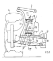
- the wheel suspension comprises a double wishbone consisting of a lower link 1 and an upper link 2, which are hinged to a wheel carrier 3 which is connected to the wheel 4. This is driven by a drive shaft 5 which is arranged in the vehicle transverse direction.
- a bolt 10 is fastened on the side of the handlebar 1, on which the guide element 6 is supported.
- the guide element 6 is provided with a stem 11 oriented vertically upwards from the bolt 10, which extends at the end to the spring plate 8, which is arranged above the drive shaft 5. This runs near the stem 11 through a free space 14 formed between the spring plate and the stem 11 and intersects the projected surface of the spring plate 8 and is arranged with a partial area within the enveloping cylinder 18 of the coil spring 7.
- An auxiliary link 12 is connected to the guide element 6 in the area of the arm 11, which extends in the transverse direction of the vehicle and can be pivoted about an axis 17 on the vehicle body 13 and about an axis 19 on the arm 11.
- the lower spring plate 8 of the guide element 6 moves approximately parallel to the upper spring plate 15 due to its guidance over the auxiliary link 12 during suspension processes
Landscapes
- Engineering & Computer Science (AREA)
- Mechanical Engineering (AREA)
- Vehicle Body Suspensions (AREA)
Abstract
Description
- Die Erfindung bezieht sich auf eine Radaufhängung nach dem Oberbegriff des Anspruchs 1.
- Aus der DE-PS 34 05 174 ist eine Radaufhängung bekannt, bei der eine Schraubenfeder getrennt von einem Dämpfer an einem Radführungsglied abgestützt ist. Die Schraubenfeder erstreckt sich bis in eine Ebene unterhalb einer Rad-Antriebswelle, in der das Radführungsglied an einem Radträger schwenkbeweglich gelagert wird. Damit die Schraubenfeder berührungsfrei zur quer zum Rad durchgeführten Antriebswelle anzuordnen ist, weist sie in diesem Bereich ein windungsfreies Verbindungsstück auf. Dieses verbindet das obere Federteil mit dem unteren Federteil und ermöglicht einen Verlauf der Antriebswelle durch den Hüllzylinder der Schraubenfeder. Bei einer solchen Ausführung nimmt die untere am Lenker befestigte Federauflage immer den Neigungswinkel des Lenkers ein, was zu einem Ausknicken der Schraubenfeder führen kann.
- Aufgabe der Erfindung ist es, eine Radaufhängung mit einer separat zu einem Federbein angeordneten Schraubenfeder zu schaffen, die einen Freiraum für eine Antriebswelle aufweist und eine optimale Führung der Schraubenfeder gewährleistet.
- Diese Aufgabe wird erfindungsgemäß durch die kennzeichnenden Merkmale des Anspruchs 1 gelöst. Weitere vorteilhafte Merkmale beinhalten die Unteransprüche.
- Die mit der Erfindung hauptsächlich erzielten Vorteile bestehen darin, daß bei einer Doppelquerlenkerachse trotz einer getrennt von einem Federbein angeordneten Schraubenfeder, die oberhalb einer Rad-Antriebswelle an einem Führungselement abgestützt ist, eine relativ große Dämpferübersetzung erreicht wird. Durch die Hilfskonstruktion eines geführten unteren Federtellers kann die Schraubenfeder separat angeordnet werden, was für die Erhöhung der Dämpferübersetzung genutzt wird.
- Damit ein Ausknicken oder ein Abspringen der nicht geführten Schraubenfeder in den Extremstellungen vermieden wird, ist die Schraubenfeder in vorteilhafter Weise auf einem am unteren Querlenker drehbar gelagerten Federteller abgestützt. Dieser Federteller wird zusätzlich über einen Hilfslenker geführt, der bei einer parallelen Anordnung zum unteren Querlenker eine annähernd parallele Führung des unteren Federtellers zur oberen Federauflage gewährleistet, so daß ein Ausknicken der Schraubenfeder vermieden wird.
- Neben diesen Vorteilen wird durch das mit dem Querlenker verbundene Führungselement erreicht, daß die zu den Rädern geführten Antriebswellen frei von der Schraubenfeder verlaufen können, ohne diese auch bei extremen Fahrzuständen zu berühren. Hierzu ist das Führungselement mit einem etwa vertikal ausgerichteten Stiel versehen, an dem die Antriebswelle vorbeiläuft.
- Ein Ausführungsbeispiel der Erfindung ist in der Zeichnung dargestellt und wird im folgenden näher beschrieben.
- Es zeigen:
- Fig .1 eine Vorderansicht der Radaufhängung bei ein- und ausgefedertem Rad,
- Fig .2 einen Schnitt nach der Linie II-II der Fig. 1.
- Die Radaufhängung umfaßt einen Doppelquerlenker bestehend aus einem unterem Lenker 1 und einem oberen Lenker 2, die an einem Radträger 3 angelenkt sind, der mit dem Rad 4 verbunden ist. Dieses wird von einer Antriebswelle 5 getrieben, welche in Fahrzeugquerrichtung angeordnet ist.
- Auf dem unteren Querlenker 1 ist unter Zwischenschaltung eines Führungselements 6 eine Schraubenfeder 7 gelagert, die sich auf einen Federteller 8 des Elements 6 abstützt. Dieses ist am unteren Lenker 1 um eine in Fahrzeuglängsrichtung verlaufende Achse 9 schwenkbar gehalten. Hierzu ist seitlich des Lenkers 1 ein Bolzen 10 befestigt, auf dem sich das Führungselement 6 abstützt.
- Das Führungselement 6 ist mit einem vom Bolzen 10 vertikal aufwärts ausgerichteten Stiel 11 versehen, der sich endseitig zu dem Federteller 8 erweitert, welcher oberhalb der Antriebswelle 5 angeordnet ist. Diese verläuft nahe des Stiels 11 durch einen gebildeten Freiraum 14 zwischen dem Federteller und dem Stiel 11 und schneidet die projizierte Fläche des Federtellers 8 und ist mit einem Teilbereich innerhalb des Hüllzylinders 18 der Schraubenfeder 7 angeordnet.
- Mit dem Führungselement 6 ist im Bereich des Stiels 11 ein Hilfslenker 12 verbunden, der sich in Fahrzeugquerrichtung erstreckt und um eine Achse 17 am Fahrzeugaufbau 13 sowie um eine Achse 19 am Stiel 11 schwenkbar ist.
- Wie in Fig. 1 näher gezeigt ist, bewegt sich der untere Federteller 8 des Führungselements 6 aufgrund seiner Führung über den Hilfslenker 12 bei Federungsvorgängen annähernd parallel zum oberen Federteller 15
Claims (4)
Applications Claiming Priority (2)
| Application Number | Priority Date | Filing Date | Title |
|---|---|---|---|
| DE3836561 | 1988-10-27 | ||
| DE3836561A DE3836561A1 (de) | 1988-10-27 | 1988-10-27 | Radaufhaengung |
Publications (2)
| Publication Number | Publication Date |
|---|---|
| EP0365795A1 true EP0365795A1 (de) | 1990-05-02 |
| EP0365795B1 EP0365795B1 (de) | 1992-11-11 |
Family
ID=6366003
Family Applications (1)
| Application Number | Title | Priority Date | Filing Date |
|---|---|---|---|
| EP89116305A Expired - Lifetime EP0365795B1 (de) | 1988-10-27 | 1989-09-04 | Radaufhängung |
Country Status (4)
| Country | Link |
|---|---|
| US (1) | US4984818A (de) |
| EP (1) | EP0365795B1 (de) |
| DE (2) | DE3836561A1 (de) |
| ES (1) | ES2035483T3 (de) |
Cited By (2)
| Publication number | Priority date | Publication date | Assignee | Title |
|---|---|---|---|---|
| DE4331365A1 (de) * | 1993-09-15 | 1995-03-16 | Bayerische Motoren Werke Ag | Fahrzeug-Radaufhängung in Dämpferbeinbauart |
| CN109624639A (zh) * | 2018-10-31 | 2019-04-16 | 华中科技大学 | 一种z形多连杆行程放大的车辆悬挂系统用液压升降机构 |
Families Citing this family (5)
| Publication number | Priority date | Publication date | Assignee | Title |
|---|---|---|---|---|
| JPH0976714A (ja) * | 1995-09-13 | 1997-03-25 | Nissan Motor Co Ltd | 車両用リヤサスペンション |
| DE19802637C2 (de) * | 1998-01-24 | 2002-11-07 | Daimler Chrysler Ag | Federung für Fahrzeuge mit einem Federlenker |
| US20060208447A1 (en) * | 2005-03-21 | 2006-09-21 | Arvinmeritor Technology, Llc | Independent suspension for a drive axle |
| DE102011078851B4 (de) * | 2011-07-08 | 2022-03-31 | Ford Global Technologies, Llc | Radaufhängung für Kraftfahrzeuge mit Querkraftkompensation |
| JP7342808B2 (ja) * | 2020-06-30 | 2023-09-12 | トヨタ自動車株式会社 | 車輪配設モジュール |
Citations (3)
| Publication number | Priority date | Publication date | Assignee | Title |
|---|---|---|---|---|
| DE3337255A1 (de) * | 1983-10-13 | 1985-02-21 | Daimler-Benz Ag, 7000 Stuttgart | Radaufhaengung fuer angetriebene raeder von kraftfahrzeugen, insbesondere gelenkte vorderraeder |
| DE3405174C1 (de) * | 1984-02-14 | 1985-09-19 | Daimler-Benz Ag, 7000 Stuttgart | Radaufhaengung fuer Kraftfahrzeuge |
| EP0278088A2 (de) * | 1987-02-10 | 1988-08-17 | Dr.Ing.h.c. F. Porsche Aktiengesellschaft | Radaufhängung |
Family Cites Families (4)
| Publication number | Priority date | Publication date | Assignee | Title |
|---|---|---|---|---|
| DE2142523C3 (de) * | 1971-08-25 | 1974-03-28 | Daimler-Benz Ag, 7000 Stuttgart | Radaufhängung, insbesondere Vorderradaufhängung für Kraftfahrzeuge |
| DE3507141A1 (de) * | 1985-02-28 | 1986-09-04 | Bayerische Motoren Werke AG, 8000 München | Radaufhaengung fuer lenkbare raeder, insbesondere vorderraeder, von kraftfahrzeugen |
| DE3514823A1 (de) * | 1985-04-24 | 1986-11-06 | Bayerische Motoren Werke AG, 8000 München | Unabhaengige radaufhaengung fuer kraftfahrzeuge |
| DE3703196A1 (de) * | 1987-02-03 | 1988-08-11 | Bayerische Motoren Werke Ag | Radaufhaengung fuer lenkbare hinterraeder von mit vorderradlenkung ausgestatteten kraftfahrzeugen, insbesondere personenkraftwagen |
-
1988
- 1988-10-27 DE DE3836561A patent/DE3836561A1/de not_active Withdrawn
-
1989
- 1989-09-04 ES ES198989116305T patent/ES2035483T3/es not_active Expired - Lifetime
- 1989-09-04 EP EP89116305A patent/EP0365795B1/de not_active Expired - Lifetime
- 1989-09-04 DE DE8989116305T patent/DE58902698D1/de not_active Expired - Lifetime
- 1989-10-13 US US07/421,325 patent/US4984818A/en not_active Expired - Fee Related
Patent Citations (3)
| Publication number | Priority date | Publication date | Assignee | Title |
|---|---|---|---|---|
| DE3337255A1 (de) * | 1983-10-13 | 1985-02-21 | Daimler-Benz Ag, 7000 Stuttgart | Radaufhaengung fuer angetriebene raeder von kraftfahrzeugen, insbesondere gelenkte vorderraeder |
| DE3405174C1 (de) * | 1984-02-14 | 1985-09-19 | Daimler-Benz Ag, 7000 Stuttgart | Radaufhaengung fuer Kraftfahrzeuge |
| EP0278088A2 (de) * | 1987-02-10 | 1988-08-17 | Dr.Ing.h.c. F. Porsche Aktiengesellschaft | Radaufhängung |
Cited By (3)
| Publication number | Priority date | Publication date | Assignee | Title |
|---|---|---|---|---|
| DE4331365A1 (de) * | 1993-09-15 | 1995-03-16 | Bayerische Motoren Werke Ag | Fahrzeug-Radaufhängung in Dämpferbeinbauart |
| CN109624639A (zh) * | 2018-10-31 | 2019-04-16 | 华中科技大学 | 一种z形多连杆行程放大的车辆悬挂系统用液压升降机构 |
| CN109624639B (zh) * | 2018-10-31 | 2020-08-04 | 华中科技大学 | 一种z形多连杆行程放大的车辆悬挂系统用液压升降机构 |
Also Published As
| Publication number | Publication date |
|---|---|
| US4984818A (en) | 1991-01-15 |
| ES2035483T3 (es) | 1993-04-16 |
| EP0365795B1 (de) | 1992-11-11 |
| DE3836561A1 (de) | 1990-05-03 |
| DE58902698D1 (de) | 1992-12-17 |
Similar Documents
| Publication | Publication Date | Title |
|---|---|---|
| EP1937498B1 (de) | Radaufhängung für die angetriebenen hinterräder eines kraftfahrzeugs | |
| EP0312711A2 (de) | Radaufhängung für ein Kraftfahrzeug | |
| EP1057665A1 (de) | Achsaufhängung für Starrachsen in Fahrzeugen | |
| DE2558322A1 (de) | Hinterradaufhaengung fuer kraftfahrzeuge | |
| EP0389685B1 (de) | Radaufhängung für die Vorderräder eines Kraftfahrzeuges | |
| DE2260045C3 (de) | Aufhängung für eine abgefederte starre Zusatzradachse für Kraftfahrzeuge | |
| DE3307543C2 (de) | Radaufhängung für angetriebene Räder von Kraftfahrzeugen | |
| DE3703198C1 (de) | Radaufhaengung fuer lenkbare Hinterraeder von mit Vorderradlenkung ausgestatteten Kraftfahrzeugen,insbesondere Personenkraftwagen | |
| EP0364713B1 (de) | Radaufhängung | |
| EP0365795B1 (de) | Radaufhängung | |
| AT391110B (de) | Radfuehrung fuer lenkbare und antriebsfaehige raeder von kraftfahrzeugen | |
| DE3151369A1 (de) | Radaufhaengung | |
| DE1680048C3 (de) | Radaufhängung für Kraftfahrzeuge | |
| EP0802075A2 (de) | Hilfsrahmen | |
| DE3918358A1 (de) | Radaufhaengung fuer fahrzeuge | |
| DE2822066C2 (de) | Einzelradaufhängung, insbesondere für Lastkraftwagen | |
| DE4413146C2 (de) | Luftgefederte Achse eines Kraftfahrzeuges, insbesondere für Omnibusse und Lastkraftwagen | |
| DE3148015C2 (de) | Luftgefederte Starrachse für Nutzfahrzeuge | |
| DE10232329A1 (de) | Kraftwagenkarosserie mit einer Strebenanordnung | |
| DE1269637B (de) | Federnde Achslageraufhaengung, insbesondere fuer Schienenfahrzeuge | |
| DE2260004C3 (de) | Scheinwerferwischer für Doppelscheinwerfer | |
| DE102019005557B3 (de) | Radaufhängung für einen Kraftwagen, insbesondere für einen Personenkraftwagen, sowie Kraftwagen mit wenigstens einer solchen Radaufhängung | |
| DE814392C (de) | Hinterradabfederung, insbesondere fuer Kraftfahrzeuge | |
| DE3714686C1 (en) | Wheel suspension for motor vehicles | |
| DE3924828A1 (de) | Unabhaengige aufhaengung eines gelenkten rades von kraftfahrzeugen |
Legal Events
| Date | Code | Title | Description |
|---|---|---|---|
| PUAI | Public reference made under article 153(3) epc to a published international application that has entered the european phase |
Free format text: ORIGINAL CODE: 0009012 |
|
| AK | Designated contracting states |
Kind code of ref document: A1 Designated state(s): DE ES FR GB IT NL |
|
| 17P | Request for examination filed |
Effective date: 19900905 |
|
| 17Q | First examination report despatched |
Effective date: 19911010 |
|
| ITF | It: translation for a ep patent filed | ||
| GRAA | (expected) grant |
Free format text: ORIGINAL CODE: 0009210 |
|
| AK | Designated contracting states |
Kind code of ref document: B1 Designated state(s): DE ES FR GB IT NL |
|
| REF | Corresponds to: |
Ref document number: 58902698 Country of ref document: DE Date of ref document: 19921217 |
|
| GBT | Gb: translation of ep patent filed (gb section 77(6)(a)/1977) |
Effective date: 19921127 |
|
| ET | Fr: translation filed | ||
| REG | Reference to a national code |
Ref country code: ES Ref legal event code: FG2A Ref document number: 2035483 Country of ref document: ES Kind code of ref document: T3 |
|
| PGFP | Annual fee paid to national office [announced via postgrant information from national office to epo] |
Ref country code: ES Payment date: 19930907 Year of fee payment: 5 |
|
| PLBE | No opposition filed within time limit |
Free format text: ORIGINAL CODE: 0009261 |
|
| STAA | Information on the status of an ep patent application or granted ep patent |
Free format text: STATUS: NO OPPOSITION FILED WITHIN TIME LIMIT |
|
| PGFP | Annual fee paid to national office [announced via postgrant information from national office to epo] |
Ref country code: NL Payment date: 19930930 Year of fee payment: 5 |
|
| 26N | No opposition filed | ||
| PGFP | Annual fee paid to national office [announced via postgrant information from national office to epo] |
Ref country code: GB Payment date: 19940830 Year of fee payment: 6 |
|
| PG25 | Lapsed in a contracting state [announced via postgrant information from national office to epo] |
Ref country code: ES Free format text: LAPSE BECAUSE OF EXPIRATION OF PROTECTION Effective date: 19940905 |
|
| PGFP | Annual fee paid to national office [announced via postgrant information from national office to epo] |
Ref country code: DE Payment date: 19940913 Year of fee payment: 6 |
|
| PGFP | Annual fee paid to national office [announced via postgrant information from national office to epo] |
Ref country code: FR Payment date: 19940928 Year of fee payment: 6 |
|
| PG25 | Lapsed in a contracting state [announced via postgrant information from national office to epo] |
Ref country code: NL Effective date: 19950401 |
|
| NLV4 | Nl: lapsed or anulled due to non-payment of the annual fee | ||
| PG25 | Lapsed in a contracting state [announced via postgrant information from national office to epo] |
Ref country code: GB Effective date: 19950904 |
|
| GBPC | Gb: european patent ceased through non-payment of renewal fee |
Effective date: 19950904 |
|
| PG25 | Lapsed in a contracting state [announced via postgrant information from national office to epo] |
Ref country code: FR Effective date: 19960531 |
|
| PG25 | Lapsed in a contracting state [announced via postgrant information from national office to epo] |
Ref country code: DE Effective date: 19960601 |
|
| REG | Reference to a national code |
Ref country code: FR Ref legal event code: ST |
|
| REG | Reference to a national code |
Ref country code: ES Ref legal event code: FD2A Effective date: 19990601 |
|
| PG25 | Lapsed in a contracting state [announced via postgrant information from national office to epo] |
Ref country code: IT Free format text: LAPSE BECAUSE OF NON-PAYMENT OF DUE FEES;WARNING: LAPSES OF ITALIAN PATENTS WITH EFFECTIVE DATE BEFORE 2007 MAY HAVE OCCURRED AT ANY TIME BEFORE 2007. THE CORRECT EFFECTIVE DATE MAY BE DIFFERENT FROM THE ONE RECORDED. Effective date: 20050904 |