EP0365879A2 - Contact électrique avec métal de base - Google Patents
Contact électrique avec métal de base Download PDFInfo
- Publication number
- EP0365879A2 EP0365879A2 EP89118329A EP89118329A EP0365879A2 EP 0365879 A2 EP0365879 A2 EP 0365879A2 EP 89118329 A EP89118329 A EP 89118329A EP 89118329 A EP89118329 A EP 89118329A EP 0365879 A2 EP0365879 A2 EP 0365879A2
- Authority
- EP
- European Patent Office
- Prior art keywords
- contact
- base metal
- contact material
- die forging
- welded
- Prior art date
- Legal status (The legal status is an assumption and is not a legal conclusion. Google has not performed a legal analysis and makes no representation as to the accuracy of the status listed.)
- Granted
Links
Images


Classifications
-
- H—ELECTRICITY
- H01—ELECTRIC ELEMENTS
- H01H—ELECTRIC SWITCHES; RELAYS; SELECTORS; EMERGENCY PROTECTIVE DEVICES
- H01H1/00—Contacts
- H01H1/02—Contacts characterised by the material thereof
- H01H1/021—Composite material
- H01H1/023—Composite material having a noble metal as the basic material
- H01H1/0237—Composite material having a noble metal as the basic material and containing oxides
-
- H—ELECTRICITY
- H01—ELECTRIC ELEMENTS
- H01H—ELECTRIC SWITCHES; RELAYS; SELECTORS; EMERGENCY PROTECTIVE DEVICES
- H01H11/00—Apparatus or processes specially adapted for the manufacture of electric switches
- H01H11/04—Apparatus or processes specially adapted for the manufacture of electric switches of switch contacts
- H01H11/041—Apparatus or processes specially adapted for the manufacture of electric switches of switch contacts by bonding of a contact marking face to a contact body portion
- H01H11/043—Apparatus or processes specially adapted for the manufacture of electric switches of switch contacts by bonding of a contact marking face to a contact body portion by resistance welding
Definitions
- the present invention relates to an electric contact with a base metal for use in a current switch, such as an electromagnetic contactor.
- non-oxide contact materials of Ag and Ag-Ni or Ag-oxide contact materials in which an oxide including Cd, Sn, Sb, In, Zn, Mn, Te, Bi, or the like is dispersed in Ag can be used as an electric contact (hereinafter referred to as "contact") with a base metal in a current switch.
- the Ag-oxide contact material exhibits excellent contact characteristics in view of deposition- and wear-resistance and, therefore, is employed mainly in a medium load range.
- the contact is joined to a base metal when used for a switch.
- the contact is joined metallurgically by brazing or resistance welding.
- the base metal When the contact is formed by brazing, the base metal is softened since the base metal and the contact have to be heated at high temperatures. The thickness of the base metal also has to be increased. Using the brazing method, therefore, is undesirable for reducing the switch in size. Moreover, the brazing method is unfit for mass production of switches because the automated operation of joining contacts and base metals is difficult.
- a resistance welding method is superior to the brazing method because with resistance welding the base metal is less affected by heat, and the operation can be automated. Current is passed across the joint between the contact material and the base metal, and causes the material to be joined instantaneously. The contact material joined to the base metal by resistance welding is subsequently compression-molded vertically into a round or square contact.
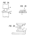
- Fig. 34 shows a process of joining a contact material to a base metal by resistance welding.
- Fig. 35 shows a contact formed by die forging of the contact material thus joined by resistance welding.
- a contact material 1 prepared by cutting a circular wire is laid in place on a base metal 2.
- Current then flows between electrodes 4A and 4B with the contact material 1 and the base metal 2 held therebetween.
- Due to contact resistance electrically-induced heat is generally in the joint between the contact material 1 and the base metal 2.
- the joint is fused so as to weld the contact material 1 to the base metal 2 within a range of weld metal zone 3.
- the contact material 1 joined to the base metal 2 by resistance welding is vertically compressed by means of a mold (not shown) into a disc-like contact 5 shown in Fig. 35.
- numerals 5 and 6 designate a fixed and a moving contact, respectively.
- the contact 5 is heated by an arc 7 when the contacts 5 and 6 are separated and contact 5 is cooled after the arc 7 is extinguished.
- the surface of the contact constracts during the course of cooling and consequently the force resulting from the concentration of the heat at the center is applied to the outer periphery of the contact 5 in such a direction as to make the outer periphery thereof peel off.
- transmission of heat of the base metal 2 diminishes and this causes the contact 5 to be increasingly heated and peeled off.
- the contact may undergo abnormal wear or drop off from the basemetal 2.
- the arc is often driven by a magnetic force in a fixed direction (e.g., in the direction of arrow P of Fig. 36) during the period between its generation and termination.
- contact peeling tends to be biased toward the terminal end of the movement of the arc.
- an object of the present invention is to provide a peeling-resistance electric contact made by joining a contact material to a base metal, having a contact promoting shape, by resistance welding which less thermally affects the base metal but yields excellent automated production capabilities.
- Another object of the present invention is to provide a peeling-resistant electric contact made by joining to a base metal, having a contact promoting shape, a contact material made of Ag-oxide contact material which exhibits excellent electrical characteristics.
- an electric contact with a base metal having a contact promoting shape, the combination of which is formed by die forging of a contact material joined to the base metal by resistance welding the contact material to the contact promoting shape of the base metal, at least one side of the contact material in contact with the base metal is formed of non-oxide contact material and bites into the base metal.
- the contact material subjected to die forging fills a groove or hole preformed in the base metal close to a weld zone where the base metal and the contact material are welded together.
- the groove may be a series of dots.
- the contact material also may be welded to protrusions preformed in a weld zone of the base metal to which the contact material is welded.
- the contact material may be welded to the bottom of a cut preformed in and laterally across the base metal.
- each periphery of the contact material subjected to die forging will contact the interior wall of the cut that is most vertical and the peel resistance effect of the contact is improved.
- the contact material may be welded to bottoms of recesses preformed in the contact-fitting portion of the base metal. As with the previous example, each periphery of the contact material subjected to die forging will contact the interior wall of the recess that is most vertical.
- a composite wire may be employed as the contact material to improve deposition- and wear-resistance.
- the composite wire is prepared by coating and outer periphery of a core material made of Ag-metallic oxide contact material with the non-oxide contact material.
- the sectional area of the non-oxide contact material may account for 5% to 35% of the total sectional area of the composite wire, as will be discussed later.
- the surface layer for switching purposes should be ground after die forging to expose the core material.
- the joint surface of the contact material that joins the base metal should at least be formed of non-oxide contact material of Ag, Ag-Ni, or the like. This will secure the welding strength of the central portion of the contact.
- the portion biting into the base metal on the periphery of the contact resists the force applied in the direction in which it is to deform around the weld zone. However, that portion shows no resistance against the force applied in the axial direction in which it slips out after the weld zone has peeled off. If the surface of the contact material that joins the base metal is formed of a flexible Ag or Ag alloy, however, the contact material will readily fill the grooves or holes formed in the base metal, and the biting performance will be improved.
- a composite wire may be used as the contact material. It is preferred to use a composite wire prepared by coating the outer periphery of a core material made of Ag-oxide contact material as the contact material with the non-oxide contact material.
- a composite wire improves weldability of the contact to the base metal because of the Ag or Ag alloy on the outer periphery of the core material and further the contact material after welding is easily bitten into the base metal at die forging.
- the composite wire also facilitates the fabrication of the contact since the outer periphery of the hard Ag-oxide contact material is coated and protected with the Ag or Ag alloy.
- the sectional area of the non-oxide contact material is set at 5% to 35%. If the percentage is set at non high than 5%, the core material may be exposed at the time of welding. Furthermore, decreasing the amount of contact material biting into the base metal decreases the joint strength. On the other hand, if the percentage is set at not lower than 35%, the excessive Ag or Ag alloy content decreases the deposition-resistance contact characteristics. With the percentage of non-oxide material set at 5% to 35%, the surface layer for switching purposes is ground to have the core material exposed after the contact material is subjected to die forging. Moreover, the deposition-resistance is further improved when composite wire is employed.
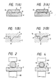
- contact material 1 is prepared by cutting an Ag-Ni wire 2.6 mm in diameter to a length of 2.6 mm and laying it on a base metal 2 of 1.5 mm thick and 7.0 mm wide with grooves 8 provided close to a weld zone where the contact material 1 is welded.
- Contact material 1 is welded to the base metal 2 within a range of weld zone 3 by supplying power between electrodes 4A, 4B, as shown in Fig. 2.
- Contact material 1 is then subjected to die forging by means of a mold to make round contact 9 of 4.7 mm diameter having a flat surface as shown if Fig. 1.
- the contact material 1 after die forging bites into the groove 8, by pressing the contact material to fill the groove 8.
- Two kinds of grooves 8 are provided in the base metal 2 as follows: two V-shaped grooves, each being 0.4 mm deep and 0.8 mm wide, are provided on both sides of contact material 1 at each interval of 3 mm as shown, and a ring-like V-shaped groove similar in depth and width and having a diameter of 3 mm is provided around the contact material 1.
- a base metal similar in dimensional conditions to the aforementioned samples, but free of grooves, are prepared at the same time.
- Figs. 3 and 4 correspond to Example 2. Plus, Fig. 5 is an enlarged photograph illustrating the metal composition of the groove in section. Unlike Example 1, a composite wire of 2.6 mm in diameter, prepared by joining a silver covering material 1b 0.1 mm thick to a core material 1a of Ag-CdO, is used as contact material 1. Base metal 2, groove 8, and contact 9 after die forging are similar to those in Example 1 in dimensions and shapes, etc.
- the outer wall surface of groove 8 shown in Fig. 1(B) and Fig. 3(B), respectively, makes an angle of ⁇ , which is approximately 90° to the surface of the base metal.
- the derivation of angle ⁇ from 90° should be as small as possible to increase the peel resistant effect. If the angle ⁇ exceeds 90°, the groove may readily be formed by punching. On the other hand, if the angle ⁇ is not greater than 90°, the contact material becomes virtually impossible to process.
- the peel resistant force of the contact generated at the time of current switching is affected by the size of current, the switching frequency, the size of contact, the material quality of the contact and so on.
- the angle ⁇ therefore, should be determined in consideration of the relationship between those conditions and the processability of the groove.
- the resulting powdor is subjected to internal oxidation and formed into a round bar 80 mm in diameter and 200 mm long before being sintered.
- This billet is heated at 800°C in the atmosphere and then extruded by a hot extruder into a round bar 20 mm in diameter.
- the quantitative analysis value of Ag at this time is approximately 85.0% (85Ag-CdO) because of an increase in oxygen.
- the round bar of Ag-CdO is fitted into an Ag pipe 1.0 mm thick and 20.1 mm in inner diameter before being heated at 800°C. Hot working is then employed to join Ag and Ag-CdO into a composite round bar.
- This round composite bar is repeatedly annealed and swagged to prepare a composite wire 3.0 mm in diameter.
- the ratio of the Ag layer area to the total sectional area of the composite wire will be approximately 17%.
- This composite wire is cut to a length of 3 mm to provide composite contact material (i).
- a total of 10,000 g, 9,000 g of Ag powder and 1,000 g of oxidized Sn powder, are mixed by a V-type mill and the mixture is formed into a round bar 80 mm in diameter and 200 mm long before being sintered.
- This billet is heated at 850°C in the atmosphere and then extruded by a hot extruder into a round bar 20 mm in diameter (90Ag-SnO2).
- the round bar of Ag-SnO2 is fitted into a 99.8 wt% Ag-Ni alloy pipe 2 mm thick and 20.1 mm inner diameter before being heated at 850°C. Hot working is then employed to join Ag and Ag-SnO2.
- This round composite bar is repeatedly annealed and swagged to prepare a composite wire 3.0 mm in diameter.
- the ratio of the Ag alloy layer area to the total sectional area of the composite wire will be approximately 30%.
- This composite wire is cut to a length of 3 mm to provide composite contact material (ii).
- the resulting powder is subjected to internal oxidation and formed into a round bar 80 mm in diameter and 200 mm in length before being sintered.
- This billet is heated at 800°C in the atmosphere and then extruded by a hot extruder into a round bar 20 mm in diameter.
- the quantitative analysis value of Ag at this time will be approximately 90% (90Ag-CdO) because of an increase in oxygen.
- the round bar of Ag-CdO is fitted into an Ag pipe 1.5 mm thick and 20.1 mm in inner diameter before being heated at 800°C. Hot working is then employed to join Ag and Ag-CdO in to a composite round bar.
- This round composite bar is repeatedly annealed and swagged to prepare a composite wire 3.0 mm in diameter.
- the ratio of the Ag alloy layer area to the total sectional area of the composite wire will be approximately 24%.
- This composite wire is cut to a length of 3 mm to provide a composite contact material (iii).
- a total of 10,000 g, 8,800 g of Ag powder, 880 g of oxidized Cd powder and 400 g of oxidized Sn power, are mixed by the V-type mill and the mixture is formed into a round bar 80 mm in diameter and 200 mm long before being sintered.
- This billet is heated at 850°C in the atmosphere and then extruded by a hot extruder into a round bar 20 mm in diameter (88Ag-8CdO-SnO2).
- the round bar of Ag-CdO-SnO2 is fitted into a 99.5 wt% Ag-Cu alloy pipe 0.5 mm thick and 20.1 mm in inner diameter before being heated at 850°C. Hot working is then employed to join Ag-Cu and Ag-CdO-SnO2.
- This round composite bar is repeatedly annealed and swagged to prepare a composite wire 3.0 mm in diameter.
- the ratio of the Ag alloy layer area to the total sectional area of the composite wire will be approximately 9%.
- This composite wire is cut to a length of 3 mm to provide composite contact material (iv).
- the resulting powder is subjected to internal oxidation and formed into a round bar 80 mm in diameter and 200 mm in length before being sintered.
- This billet is heated at 800°C in the atmosphere and then extruded by a hot extruder into a round bar 20 mm in diameter.
- the quantitative analysis value of Ag at this time is approximately 86.5% (86.5Ag-CdO) because of an increase in oxygen.
- the round bar of Ag-CdO is fitted into an Ag pipe 1.0 mm thick and 20.1 mm in inner diameter before being heated at 800°C.
- This round composite bar is repeatedly annealed and swagged to prepare a composite wire 3.0 mm in diameter.
- the ratio of the Ag layer area to the total sectional area of the composite wire will be approximately 9%.
- This composite wire is cut to a length of 3 mm to provide a composite contact material (v).
- This billet is heated at 850°C in the atmosphere and then extruded by a hot extruder into a round bar 20 mm in diameter (88Ag-SnO2).
- the round bar of Ag-SnO2 is fitted into a 99.5 wt% Ag-Ni alloy pipe 2 mm thick and 20.1 mm in inner diameter before being heated at 850°C. Hot working is then employed to join Ag-Ni and Ag-SnO2.
- This round composite bar is repeatedly annealed and swagged to prepare a composite wire 3.0 mm in diameter.
- the ratio of the Ag alloy layer area to the total sectional area of the composite wire is approximately 30%.
- This composite wire is cut to a length of 3 mm to provide a composite contact material (vi).
- Ag-CdO and Ag-SnO2 are discussed as the core materials for the contact materials i-vi, use can be made of Ag-oxide contact materials containing various oxides includes Cd, Sn, Sb, In, Zn, Mn, Te, Bi, etc.
- core material made of Ag-oxide contact material were made into comparative contacts a, b, c, d, e, and f in the form of a wire 3 mm in diameter.
- the comparative examples were made by repeatedly annealing and extruding the material into the round bar 20 mm in diameter of 85Ag-CdO as a , 90Ag-SnO2 as b , 90Ag-CdO as c , 88Ag-8CdO-SnO2 as d , 86.5 Ag-CdO as e , or 88Ag-SnO2 as f and cutting to a length of 3 mm.
- Examples 3-6 using contact material (i)-(iv) were compared with examples using comparative contact material a-f.
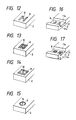
- two V-shaped grooves 8, 0.5 mm deep x 1.0 mm wide x 3.0 mm long are made in the base metal 2, 1.5 mm thick x 7.0 mm wide at a 3 mm interval.
- the aforementioned contact material (i) is joined to the base metal by resistance welding and the contact material is subjected to die forging into a substantially square contact 0.8 mm thick x 5.0 mm wide. Further, the switching surface of the contact is ground to expose the Ag-CdO layer.
- two pairs of V-shaped grooves 8, 0.1 mm deep x 0.75 mm wide x 5.0 mm long are made in the base metal 2, 1.5 mm thick x 7.0 mm wide at a 2 mm interval.
- the aforementioned contact material (ii) is joined to the base metal by resistance welding and the material is subjected to die forging into a substantially square contact 0.8 mm thick x 5.0 mm wide. Further, the switching surface of the contact is ground to expose the Ag-SnO2 layer.
- FIG. 8 As shown in Fig. 8, four V-shaped grooves 8, 0.7 mm deep x 0.2 mm wide x 3.0 mm long are made in the base metal 2, 1.5 mm thick x 7.0 mm wide at a 2 mm interval in a square form.
- the aforementioned contact material (iii) is joined to the base metal by resistance welding and the material is subjected to die forging into a substantially square contact 0.8 mm thick x 5.0 mm wide. Further, the switching surface of the contact is ground to expose the Ag-CdO layer.
- FIG. 9 As shown in Fig. 9, four V-shaped grooves 8, 0.5 mm deep x 1.2 mm wide x 2.8 mm long are made in the base metal 2, 1.5 mm thick x 7.0 mm wide at a 2 mm interval in a ring form.
- the aforementioned contact material (iv) is joined to the base metal by resistance welding and the material is subjected to die forging into a substantially square contact 0.8 mm thick x 5.0 mm wide per side. Further, the switching surface of the contact is ground to expose the Ag-CdO-SnO2 layer.
- a comparative example of a contact material a was welded to a base metal 2 of Fig. 6 and ground as in the case of Example 3.
- a comparative example of a contact material b was welded to the base metal 2 of Fig. 7 and ground as in the case of Example 4.
- a comparative example of a contact material c was welded to the base metal 2 of Fig. 8 and ground as in the case of Example 3.
- a comparative example of a contact material d was welded to the base metal 2 of Fig. 9 and ground as in the case of Example 4.
- the contacts thus obtained were incorporated in commercially available electromagnetic contactors (read at 20 A), and switched on and off 20,000 times under the conditions including voltage at AC 220 V, current at 120 A, power factor at 0.35, and switching frequency at 600 times per hour.
- Examples 3-6 were made as discussed above and used in a similar fashion to the comparative examples in order to compare wear condition. Table 1 shows the results obtained. As in obvious from Table 1, the comparative examples deformed in the form of a bow because every one of them had not sufficient joint strength and fell off at about 10,000 switchings. The examples of the present invention were free from curved deformation and showed normal wear.
- contact material 1 made of composite contact material (i) is welded by projection welding to the base metal 2 of Fig. 12.
- One protrusion 10 is provided in the contact material welding zone of Fig. 6. The material is subjected to die forging into a substantially square contact 0.8 mm thick x 5.0 mm wide per side as shown in Fig. 11.
- Composite contact material (ii) is welded by projection welding to the base metal 2 of Fig. 13.
- Two protrusions 10 are provided in the contact material welding zone of Fig. 7. The material is subjected to die forging as in the case of Example 7.
- Composite contact material (iii) is welded by projection welding to the base metal 2 of Fig. 14.
- One protrusion 10 is provided in the contact material welding zone of Fig. 8. The material is subjected to die forging.
- Composite contact material (iv) is welded by projection welding to the base metal 2 of Fig. 15.
- One protrusion 10 is provided in the contact material welding zone of Fig. 9. The material is subjected to die forging.
- Comparative Examples 7-10 were prepared by joining comparative contact material a - d by projection welding to the base metals 2 of Figs. 2-15 and they are subjected to die forging into substantially square contacts 0.8 mm thick x 5.0 mm wide per side. Table 2 shows the test results under the same conditions as that of Examples 3-6. Examples 7.10 of the present invention were free from curved deformation and showed normal wear.
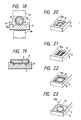
- a cut 11, 1.5 mm thick x 7.0 mm wide is preformed by cutting in and laterally across the contact-fitting portion of the base metal.
- V-shaped grooves 8 similar to those shown in Fig. 6 are provided in the bottom of the base metal.
- contact material (v) is welded to the base metal by resistance welding and the material is subjected to die forging into a substantially square contact 0.8 mm thick x 5.0 mm wide per side. At this time, each peripheral edge of the contact is then forced to contact the wall surface 11a of the cut 11.
- Comparative Examples 11 and 12 were prepared by joining comparative contact materials e and f by welding to the base metals 2 of Figs. 16 and 17 and they are subjected to die forging so that each peripheral edge was in contact with the wall surface 11a of cut 11.
- Table 3 shows the test results under the same condition as that of Examples 3-6.
- Examples 11-12 of the present invention were free from curved deformation and shown normal wear.
- a recess 12, 1.5 mm thick x 7.0 mm wide is preformed by extrusion molding in and laterally across the contact-fitting portion of the base metal.
- V-shaped grooves 8 similar to those shown in Fig. 6 are provided in the bottom of the case metal.
- Contact material (i) made of the contact material 1 is welded to the base metal by resistance welding as shown in Fig. 18 and the material is subjected to die forging into a substantially square contact 0.8 mm thick x 5.0 mm wide per side. Each peripheral edge of the contact 9 is then forced to contact the wall surface 12a the the recess 12.
- the composite contact material (ii) provided with grooves 8 similar to those shown in Fig. 7 is welded to the base metal 2 having a recess 12 similar to what is shown in Fig. 20.
- the material is subjected to die forging and each peripheral edge of the contact 9 is forced to touch the wall surface 12a of the recess 12.
- a recess 12 similar to that shown in Fig. 20 is preformed in the base metal 2 and V-shaped grooves 8 similar to those shown in Fig. 8 are provided in the bottom thereof.
- the composite contact material (iii) is welded to the base metal having the grooves and each peripheral edge of the contact is forced to touch the wall surface 12a of the recess 12.
- a recess 12 similar to that shown in Fig. 20 is preformed in the base metal 2 and V-shaped grooves 8 similar to those shown in Fig. 9 are provided in the bottom thereof.
- the composite contact material (iv) is welded to the base metal having the grooves and each peripheral edge of the contact is forced to touch the wall surface 12a of the recess 12.
- Comparative Examples 13-16 were prepared by joining comparative contact materials a - d by welding to the base metals 2 of Figs. 20-23 and they are subjected to die forging likewise to have each peripheral edge contact the wall surface 12a of the recess 12.
- Table 4 shows the test results under the same condition as that of Example 13-16.
- Examples 13-16 of the present invention were free from curved deformation and showed normal wear, whereas Comparative Examples 13-16 deformed in the form of bow and fell off at not greater than 10,000 switchings.
- the two square through-holes 13, each being 1.0 mm wide x 2.0 mm long, are provided in the base metal 2, 0.6 mm thick x 6.0 mm wide.
- Contact material 1 made of composite material of 2.6 mm in both diameter and length and made of the same material as the composite contact material (i) are joined to the base metal 2 by resistance welding as shown in Fig. 24.
- the material is subjected to die forging into a substantially square contact 9 of 0.7 mm thick x 4.5 mm wide per side as shown in Fig. 25.
- each being 1.0 mm in diameter is provided in the base metal, 0.6 mm thick x 6.0 mm wide.
- the contact material 1 made of composite material of 2.6 mm in both diameter and length and made of the same material as the composite contact material (ii) are joined to the base metal 2 by resistance welding. The material is subjected to die forging into a substantially square contact of 0.7 mm thick x 4.5 mm wide per side.
- the contact material 1 made of composite material of 2.6 mm in both diameter and length and made of the same material as the composite contact material (iii) are joined to the base metal 2 by resistance welding. The material is subjected to die forging into a substantially square contact of 0.7 mm thick x 4.5 mm wide per side.
- the contact material 1 made of composite material of 2.6 mm in both diameter and length and made of the same material as the composite contact material (iv) are joined to the base metal 2 by resistance welding. The material is subjected to die forging into a substantially square contact of 0.7 mm thick x 4.5 mm wide per side.
- Comparative Examples 17-20 were prepared by joining comparative contact materials i-iv of 2.6 mm in both diameter and length by welding to the base metals 2 of Figs. 26 and 27 and compression-molding them likewise.
- Examples 17-20 were made as discussed above and used in a similar fashion to the comparative examples in order to compare wear condition. Table 5 shows the results obtained. As is obvious from Table 5, Comparative Examples 17-20 deformed in the form of a bow and fell off at less than 10,000 switchings. Examples 17-20 of the present invention were free from curved deformation and showed normal wear.
- a cut 11 is preformed by cutting in and laterally across the contact-fitting portion of the base metal 2, 0.6 mm thick x 6.0 mm wide and square holes 13 similar to those shown in Fig. 26 are provided in the bottom thereof.
- the contact material made of composite material of 2.6 mm in both diameter and length and made of the same material as the contact material (i) is joined to the base metal 2 by resistance welding and the material is subjected to die forging into a substantially square contact of 0.7 mm thick x 4.5 mm wide per side. Each peripheral edge of the contact is then forced to touch the wall surface 11a of the cut 11.
- a cut 11 is preformed by extrusion molding in and laterally across the contact-fitting portion of the base metal 2, 0.6 mm thick x 6.0 mm wide and circular holes 14 similar to those shown in Fig. 27 are provided in the bottom thereof.
- the contact material made of composite material of 2.6 mm in both diameter and length and made of the same material as the contact material (ii) is joined to the base metal 2 by resistance welding and the material is subjected to die forging. Each peripheral edge of the contact is then forced to touch the wall surface 11a of the cut 11.
- Contact material made of composite material of 2.6 mm in both diameter and length and made of the same material as the contact material (iii) is joined to the base metal of Fig. 28 by welding and the material is subjected to die forging. Each peripheral edge of the contact is then forced to touch the wall surface 11a of the cut 11.
- Contact material made of composite material of 2.6 mm in both diameter and length and made of the same material as the contact material (iv) is joined to the base metal of Fig. 29 by welding and the material is subjected to die forging. Each peripheral edge of the contact is then forced to touch the wall surface 11a of the cut 11.
- Comparative Examples 21-24 were prepared by joining comparative contact materials i-iv of 2.6 mm in both diameter and length by welding to the base metals 2 of Figs. 28 and 29 and they are subjected to die forging likewise.
- a recess 12 is preformed by extrusion molding in the contact-fitting portion of the base metal 2, 0.6 mm thick x 6.0 mm wide and square holes 13 similar to those shown in Fig. 26 are provided in the bottom thereof.
- the contact materials 1 made of composite material 2.6 mm in both diameter and length made of the same material as the contact material (i) is joined to the base metal 2 by resistance welding and the material is subjected to die forging into a substantially square contact 9, 0.7 mm thick x 4.5 mm wide per side as shown in Fig. 31. Each peripheral edge of the contact is then forced to touch the wall surface 12a of the contact 9.
- a recess 12 is preformed likewise in the base metal 2 and circular holes 14 similar to those shown in Fig. 27 are provided.
- the contact material made of composite material 2.6 mm in both diameter and length and made of the same material as the composite contact material (ii) is joined to the base metal 2 by welding and the material is subjected to die forging. Each peripheral edge of the contact is then forced to touch the wall surface 12a of the recess 12 of the contact.
- Comparative Examples 25-28 were prepared by joining comparative contact materials i-iv of 2.6 mm in both diameter and length by welding to the base metals 2 of Figs. 32 and 33 and the material are subjected to die forging.
- the central portion of the contact is firmly welded to the base metal and the peripheral portion is prevented from bending upwardly.
- the contact is kept from wearing abnormally and, therefore, effectively prevented from falling off in the examples of the present invention.
Landscapes
- Engineering & Computer Science (AREA)
- Manufacturing & Machinery (AREA)
- Chemical & Material Sciences (AREA)
- Composite Materials (AREA)
- Materials Engineering (AREA)
- Manufacture Of Switches (AREA)
- Contacts (AREA)
Applications Claiming Priority (6)
| Application Number | Priority Date | Filing Date | Title |
|---|---|---|---|
| JP24952288 | 1988-10-03 | ||
| JP249522/88 | 1988-10-03 | ||
| JP8092/89 | 1989-01-17 | ||
| JP809289 | 1989-01-17 | ||
| JP1217752A JP2662895B2 (ja) | 1988-10-03 | 1989-08-24 | 台金付電気接点 |
| JP217752/89 | 1989-08-24 |
Publications (3)
| Publication Number | Publication Date |
|---|---|
| EP0365879A2 true EP0365879A2 (fr) | 1990-05-02 |
| EP0365879A3 EP0365879A3 (fr) | 1991-07-03 |
| EP0365879B1 EP0365879B1 (fr) | 1996-01-03 |
Family
ID=27277871
Family Applications (1)
| Application Number | Title | Priority Date | Filing Date |
|---|---|---|---|
| EP19890118329 Expired - Lifetime EP0365879B1 (fr) | 1988-10-03 | 1989-10-03 | Contact électrique avec métal de base |
Country Status (2)
| Country | Link |
|---|---|
| EP (1) | EP0365879B1 (fr) |
| DE (1) | DE68925337T2 (fr) |
Cited By (2)
| Publication number | Priority date | Publication date | Assignee | Title |
|---|---|---|---|---|
| EP0678882A3 (fr) * | 1994-04-19 | 1996-11-20 | Marquardt Gmbh | Interrupteur électrique et son procédé de fabrication. |
| FR2933541A1 (fr) * | 2008-07-07 | 2010-01-08 | Schneider Electric Ind Sas | Procede d'assemblage par resistance d'un materiau de contact sur un support metallique, contact electrique realise par un tel procede et pastille de contact utilisee |
Family Cites Families (5)
| Publication number | Priority date | Publication date | Assignee | Title |
|---|---|---|---|---|
| US2755368A (en) * | 1953-11-27 | 1956-07-17 | Gen Motors Corp | Welding method |
| US3337947A (en) * | 1964-06-29 | 1967-08-29 | Aluminum Co Of America | Method of joining electrical contacts to aluminum parts |
| FR1448780A (fr) * | 1964-11-27 | 1966-03-18 | Bernier & Cie Ets | Procédé de pose de contacts et contacts ainsi obtenus |
| US4099043A (en) * | 1976-12-23 | 1978-07-04 | Rozmus John J | Progressive die welding of electrical contacts |
| US4523711A (en) * | 1980-09-18 | 1985-06-18 | Fuji Electric Co., Ltd. | Method for bonding silver-based contact |
-
1989
- 1989-10-03 DE DE1989625337 patent/DE68925337T2/de not_active Expired - Lifetime
- 1989-10-03 EP EP19890118329 patent/EP0365879B1/fr not_active Expired - Lifetime
Cited By (2)
| Publication number | Priority date | Publication date | Assignee | Title |
|---|---|---|---|---|
| EP0678882A3 (fr) * | 1994-04-19 | 1996-11-20 | Marquardt Gmbh | Interrupteur électrique et son procédé de fabrication. |
| FR2933541A1 (fr) * | 2008-07-07 | 2010-01-08 | Schneider Electric Ind Sas | Procede d'assemblage par resistance d'un materiau de contact sur un support metallique, contact electrique realise par un tel procede et pastille de contact utilisee |
Also Published As
| Publication number | Publication date |
|---|---|
| EP0365879A3 (fr) | 1991-07-03 |
| EP0365879B1 (fr) | 1996-01-03 |
| DE68925337T2 (de) | 1996-05-23 |
| DE68925337D1 (de) | 1996-02-15 |
Similar Documents
| Publication | Publication Date | Title |
|---|---|---|
| US4243413A (en) | Integrated Ag-SnO alloy electrical contact materials | |
| US4634824A (en) | Miniaturized electric contact assembly for microswitch | |
| US5140114A (en) | Electric contact with base metal | |
| EP0365879A2 (fr) | Contact électrique avec métal de base | |
| EP0265878B1 (fr) | Procédé de fabrication d'un assemblage de contact électrique soudé | |
| EP0540186A2 (fr) | Contact électrique composite | |
| JP2662895B2 (ja) | 台金付電気接点 | |
| KR101552428B1 (ko) | 차단기용 고산화물 은/은 합금계 전기접점 소재 | |
| JP2641549B2 (ja) | Ag―酸化物系複合接点材料およびその製造方法 | |
| KR0150217B1 (ko) | 대금을 가진 전기접점 | |
| US6049046A (en) | Electric circuit protection device having electrical parts ultrasonically joined using a brazing alloy | |
| KR920005609B1 (ko) | 대금부(台金付)전기접점 | |
| JP2641548B2 (ja) | Ag―酸化物系複合接点材料およびその製造方法 | |
| JPH10177821A (ja) | 電気接点及びその製造法 | |
| JPS643012B2 (fr) | ||
| EP1019930B1 (fr) | Procede pour joindre par ultrasons des composants electroconductrices | |
| US4417119A (en) | Liquid joint process | |
| JPH0754078A (ja) | Ag−酸化物系複合電気接点材料の製造方法 | |
| US3941971A (en) | Resistance brazing of solid copper parts to stranded copper parts with phos-silver | |
| JPH09259678A (ja) | 銀─酸化物系電気接点材料およびその製造方法 | |
| JPH10188710A (ja) | 電気接点及びその製造法 | |
| JPS62241211A (ja) | 点溶接可能なテ−プ状電気接点材料 | |
| JP3349518B2 (ja) | Agー酸化物系複合電気接点材料の製造方法 | |
| JP2777120B2 (ja) | Ag−酸化物系条材およびその製造方法 | |
| CN119480475A (zh) | 一种层状复合电接触材料及其制备方法 |
Legal Events
| Date | Code | Title | Description |
|---|---|---|---|
| PUAI | Public reference made under article 153(3) epc to a published international application that has entered the european phase |
Free format text: ORIGINAL CODE: 0009012 |
|
| 17P | Request for examination filed |
Effective date: 19891003 |
|
| AK | Designated contracting states |
Kind code of ref document: A2 Designated state(s): DE FR GB |
|
| PUAL | Search report despatched |
Free format text: ORIGINAL CODE: 0009013 |
|
| AK | Designated contracting states |
Kind code of ref document: A3 Designated state(s): DE FR GB |
|
| 17Q | First examination report despatched |
Effective date: 19930413 |
|
| GRAA | (expected) grant |
Free format text: ORIGINAL CODE: 0009210 |
|
| AK | Designated contracting states |
Kind code of ref document: B1 Designated state(s): DE FR GB |
|
| REF | Corresponds to: |
Ref document number: 68925337 Country of ref document: DE Date of ref document: 19960215 |
|
| ET | Fr: translation filed | ||
| PLBE | No opposition filed within time limit |
Free format text: ORIGINAL CODE: 0009261 |
|
| STAA | Information on the status of an ep patent application or granted ep patent |
Free format text: STATUS: NO OPPOSITION FILED WITHIN TIME LIMIT |
|
| 26N | No opposition filed | ||
| REG | Reference to a national code |
Ref country code: GB Ref legal event code: IF02 |
|
| PGFP | Annual fee paid to national office [announced via postgrant information from national office to epo] |
Ref country code: DE Payment date: 20081014 Year of fee payment: 20 |
|
| REG | Reference to a national code |
Ref country code: GB Ref legal event code: 732E Free format text: REGISTERED BETWEEN 20090212 AND 20090218 |
|
| PGFP | Annual fee paid to national office [announced via postgrant information from national office to epo] |
Ref country code: FR Payment date: 20081014 Year of fee payment: 20 |
|
| PGFP | Annual fee paid to national office [announced via postgrant information from national office to epo] |
Ref country code: GB Payment date: 20081001 Year of fee payment: 20 |
|
| REG | Reference to a national code |
Ref country code: GB Ref legal event code: 732E Free format text: REGISTERED BETWEEN 20090625 AND 20090701 |
|
| REG | Reference to a national code |
Ref country code: FR Ref legal event code: TP |
|
| REG | Reference to a national code |
Ref country code: FR Ref legal event code: TQ |
|
| REG | Reference to a national code |
Ref country code: GB Ref legal event code: PE20 Expiry date: 20091002 |
|
| PG25 | Lapsed in a contracting state [announced via postgrant information from national office to epo] |
Ref country code: GB Free format text: LAPSE BECAUSE OF EXPIRATION OF PROTECTION Effective date: 20091002 |