EP0365890A2 - Bande en matière plastique thermorétractable - Google Patents
Bande en matière plastique thermorétractable Download PDFInfo
- Publication number
- EP0365890A2 EP0365890A2 EP89118555A EP89118555A EP0365890A2 EP 0365890 A2 EP0365890 A2 EP 0365890A2 EP 89118555 A EP89118555 A EP 89118555A EP 89118555 A EP89118555 A EP 89118555A EP 0365890 A2 EP0365890 A2 EP 0365890A2
- Authority
- EP
- European Patent Office
- Prior art keywords
- metal
- longitudinal edges
- tape
- band
- shrinking
- Prior art date
- Legal status (The legal status is an assumption and is not a legal conclusion. Google has not performed a legal analysis and makes no representation as to the accuracy of the status listed.)
- Granted
Links
- 239000002184 metal Substances 0.000 claims abstract description 77
- 230000002787 reinforcement Effects 0.000 claims abstract description 11
- 239000000758 substrate Substances 0.000 claims abstract description 8
- 239000004831 Hot glue Substances 0.000 claims description 13
- 238000000034 method Methods 0.000 claims description 12
- 239000000853 adhesive Substances 0.000 claims description 7
- 230000001070 adhesive effect Effects 0.000 claims description 7
- 229910001220 stainless steel Inorganic materials 0.000 claims description 5
- 239000010935 stainless steel Substances 0.000 claims description 5
- 239000011248 coating agent Substances 0.000 claims description 4
- 238000000576 coating method Methods 0.000 claims description 4
- 239000010410 layer Substances 0.000 claims description 3
- 238000004519 manufacturing process Methods 0.000 claims description 3
- 238000000465 moulding Methods 0.000 claims description 3
- 238000007373 indentation Methods 0.000 claims 1
- 238000007789 sealing Methods 0.000 description 5
- 239000004744 fabric Substances 0.000 description 4
- 230000008719 thickening Effects 0.000 description 4
- 238000010438 heat treatment Methods 0.000 description 3
- 230000003014 reinforcing effect Effects 0.000 description 3
- 239000004821 Contact adhesive Substances 0.000 description 2
- 230000004913 activation Effects 0.000 description 2
- 238000013021 overheating Methods 0.000 description 2
- 229910000679 solder Inorganic materials 0.000 description 2
- 238000004804 winding Methods 0.000 description 2
- 238000004873 anchoring Methods 0.000 description 1
- 238000005452 bending Methods 0.000 description 1
- 229920001577 copolymer Polymers 0.000 description 1
- 230000006378 damage Effects 0.000 description 1
- 230000000694 effects Effects 0.000 description 1
- 239000011521 glass Substances 0.000 description 1
- 239000003365 glass fiber Substances 0.000 description 1
- 239000007788 liquid Substances 0.000 description 1
- 239000011159 matrix material Substances 0.000 description 1
- 239000000155 melt Substances 0.000 description 1
- 238000002844 melting Methods 0.000 description 1
- 229920000728 polyester Polymers 0.000 description 1
- 238000009958 sewing Methods 0.000 description 1
- 238000007493 shaping process Methods 0.000 description 1
Images

Classifications
-
- H—ELECTRICITY
- H02—GENERATION; CONVERSION OR DISTRIBUTION OF ELECTRIC POWER
- H02G—INSTALLATION OF ELECTRIC CABLES OR LINES, OR OF COMBINED OPTICAL AND ELECTRIC CABLES OR LINES
- H02G15/00—Cable fittings
- H02G15/08—Cable junctions
- H02G15/18—Cable junctions protected by sleeves, e.g. for communication cable
- H02G15/1806—Heat shrinkable sleeves
- H02G15/1813—Wraparound or slotted sleeves
-
- B—PERFORMING OPERATIONS; TRANSPORTING
- B29—WORKING OF PLASTICS; WORKING OF SUBSTANCES IN A PLASTIC STATE IN GENERAL
- B29C—SHAPING OR JOINING OF PLASTICS; SHAPING OF MATERIAL IN A PLASTIC STATE, NOT OTHERWISE PROVIDED FOR; AFTER-TREATMENT OF THE SHAPED PRODUCTS, e.g. REPAIRING
- B29C61/00—Shaping by liberation of internal stresses; Making preforms having internal stresses; Apparatus therefor
- B29C61/06—Making preforms having internal stresses, e.g. plastic memory
- B29C61/10—Making preforms having internal stresses, e.g. plastic memory by bending plates or sheets
Definitions
- the invention relates to a tape made of a heat-recoverable plastic with reinforcements arranged on the opposite longitudinal edges of the tape running perpendicular to the direction of shrinkage, over which a holding element is pushed, preferably after the tape has been put around a substrate to be wrapped, in order to hold the longitudinal edges together during the shrinking process.
- a wrapping sleeve which consists of a heat-shrinking fabric which is embedded in a plastic matrix.
- the two longitudinal edges which run transversely to the direction of shrinkage, are folded over like loops and thereby enclose shaped rods.
- the shaped bars form thickenings over which a locking rail is pushed that holds the longitudinal edges together as described above.
- the first-mentioned wrapping sleeve has the disadvantage that the manufacture of such sleeves is quite complex. It is also not possible to insert reinforcing fabrics, particularly in the area of the webs.
- the wrapping sleeve according to EP-OS 0 116 392 has the advantage that it is of continuous, i.e. H. in great lengths, stretched bands can be removed and assembled. Heat-shrinking or reinforcing fabrics can also be arranged in the area of the longitudinal edges provided for closing the cuff. It is disadvantageous, however, that the sealing of the gap between the thickenings is very difficult, since the heat to be applied from the outside, which is required for the activation of the hot-melt adhesive, has to penetrate twice through the wall and any adhesive tab provided.
- the invention is therefore based on the object to improve the known wrapping sleeves to the effect that they are provided on their longitudinal edges with a closure system which ensures a secure and quick seal even with fabric-reinforced or with heat-shrinking wrapping sleeves.
- the reinforcements are each formed from a metal sheet formed over the longitudinal edges and that the longitudinal edges are shaped in the manner of a spiral.
- the object is achieved in that, according to the invention, the longitudinal edges are bordered by a metal strip or metal braid, which preferably extends over the entire length, and in that the reinforcements are each formed by an elongated rod which is enveloped by the longitudinal edge regions in the manner of a loop.
- the metal band or metal braid is a metal sheet or metal braid which is bent in a U-shaped manner in cross section and which is pushed onto the longitudinal edges or is formed to run in longitudinally onto the longitudinal edges. By heating the longitudinal edges, the tape begins to shrink, increasing its wall thickness. The band edges are fixed within the metal band border. The metal band or metal braid creates a very good heat distribution, so that activation of the hot-melt adhesive causing the sealing is achieved quickly and safely.
- the longitudinal edges are folded at a right angle and the folded areas are rolled up in a spiral. This creates a relatively large contact surface between the longitudinal edges, which ensures a permanent seal.
- the metal sheet is provided, at least in the region of its molding, with slots which are perpendicular to the molding direction.
- Such jumps in diameter are present, for example, in the case of cable splices, in which the ends of the band rest on the cable sheaths and the central region of the band, for. B. surrounds the splice insert.
- the diameter of the insert can be larger by a factor of 3 to 6 than the diameter of the cable.
- the metal strip or metal mesh extends in the shrinking direction over a length which corresponds to at least three times the outer diameter of the loop.
- the outside diameter of the loop is composed of the diameter of the rod and twice the wall thickness of the band in the area of the metal band enclosure d. H. twice the wall thickness of the plastic band and four times the wall thickness of the metal band.
- the metal strip or metal braid expediently consists of stainless steel with a wall thickness or a wire diameter of 0.05 to 1.0 mm.
- the metal sheet can be corrugated.
- the metal strip or metal braid is coated with an adhesive.
- This adhesive with which the metal band or metal braid is expediently coated on both sides, serves to connect the metal band or metal braid to the plastic band and also to connect the band edge folded over to form the loop with the band.
- a low-melting solder should be preferred in order to avoid overheating of the plastic.
- the tape made of a heat-recoverable plastic has a coating of a hot-melt adhesive at least on its surface facing the object to be encased and that the metal tape is perforated at least in the area in contact with the hot-melt adhesive layer or Has breakthroughs.
- the perforations or the openings aim to improve the bendability of the longitudinal edges. It is of greater importance, however, that the perforations or openings in the shrink heater allow hot melt adhesive to escape. This is particularly advantageous at the mutual contact surface of the longitudinal edges after laying around the substrate to be encased, so that a reliable sealing of the longitudinal gap of the shrunk envelope is achieved.
- the metal strip is an expanded metal sheet.
- Another object of the invention is a method for producing a tape, in which a plastic tape is extruded, crosslinked, stretched in the heated state and cooled in the stretched state.
- This method is characterized in that the longitudinal edges extending transversely to the direction of shrinking or stretching are covered over their entire length by a metal strip or metal braid, that the longitudinal edges are shaped like loops and a flexible rod is arranged within each of the loops and that the overlapping longitudinal edge regions forming the loops are mechanically firmly connected to one another.
- the longitudinal edge areas are glued together with particular advantage.
- a heat-resistant adhesive is conveniently z. B. uses a contact adhesive.
- the longitudinal edges are expediently enclosed by the metal strip or metal braid and folded over like loops with the inclusion of the rods, and the loops are preferably glued to the rods over the entire length.
- plastic band and the metal band or metal braid may be connected mechanically, at least in the immediate vicinity of the longitudinal edges.
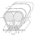
- a heat-recoverable band 1 made of plastic is shown in the cutout, which z.
- B a splice connection of an electrical cable in the manner of a wrapping sleeve and is closed on its longitudinal edges.
- the longitudinal edges of the strip 1 are each encased in a metal sheet 2 and 3, which, as shown at 4 and 5, is bent at right angles.
- the free ends of the folds 4 and 5 are rolled up in the manner of a spiral as shown at 6 and 7.
- the longitudinal edges are held together by a rail 8 which is provided with slots 9 for the purpose of better flexibility.
- the wrapping sleeve shown is placed around the substrate, the folds 4 and 5 are placed against one another and the rail 8 is pushed over the curls 6 and 7.
- the sleeve can be shrunk.
- the rail 8 holds the longitudinal edges together.
- the contact surface between the longitudinal edges is sealed.
- the region of the longitudinal edges shown in FIG. 1 is first heated.
- the strip 1 between the metal sheet surrounds 2 and 3 begins to shrink, whereby its wall thickness increases. This creates a clamp fit, in particular in the area of spirals 6 and 7.
- This clamp fit is further improved if the metal sheet has openings in which the plastic penetrates when shrinking.
- Such breakthroughs have the further advantage that a hot-melt adhesive that becomes liquid at the shrinking temperature and with which usually shrinkable tapes are coated can pass through the breakthroughs.
- Such openings are designated by 10 in FIG. 1. Characterized in that the band edges are edged in the metal sheet 2 and 3, good heat transport is ensured in the critical area for the sealing between the folds 4 and 5, so that this gap is securely sealed.
- Figures 2 and 3 each show a longitudinal edge of the band 1, which are surrounded by a sheet metal, preferably made of stainless steel.
- the metal sheet 2 has a multiplicity of openings 10 designed as elongated holes.
- Elongated holes have the advantage that they are not significantly deformed in the arrangement shown when winding the longitudinal edges into a spiral. They also make the winding process easier. With a coating of hot melt adhesive is called.
- the openings 10 are formed by using a so-called expanded metal sheet.
- expanded metal sheets are produced by making cuts in a sheet metal offset to one another and then stretching the sheet metal across the cuts.
- FIG. 8 Another embodiment of a rail 8 is shown in FIG.
- the rail 8 is produced as an endless profile from a flame-resistant plastic that is mechanically resistant at shrinking temperature.
- Glass fiber reinforced polyester is an example of a suitable plastic.
- the metal sheets 2 and 3 are expediently rolled onto the longitudinal edges after shaping. However, it is also possible to attach U-shaped metal sheets.
- the incisions in the spirals 6 and 7 and the bevels 4 and 5 should have the same distance from one another as the incisions 9 in the rail, so that a bending of the spirals 6 and 7 or the bevels 4 and 5 is not hindered during the shrinking process.
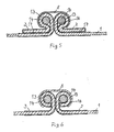
- Figures 5 and 6 each show a section through another closure system for a cuff, which is also for the wrapping of a not shown Cable connection is suitable.
- the cuff is essentially a band 1 made of a cross-linked plastic, which is pre-stretched and can be shrunk back if stretched to the dimensions before stretching.
- the longitudinal edges of the band 1 are bordered by a stainless steel sheet 2 and 3.
- the bordered by the metal sheet 2 longitudinal edge areas of the band 1 are shaped in the manner of a loop 13, in the interior of an elongated rod 14, z. B. is arranged from a variety of glass threads.
- a closure rail 8 is pushed over the reinforcements formed by the rods 14 and the loops 13, which holds the longitudinal edges of the band 1 together during the shrinking process.
- the metal sheets 2 and 3 are preferably molded onto the longitudinal edges of the stretched band 1, so that when the closure is warmed up by the shrinking behavior of the band (increase in wall thickness) self-locking occurs, so that pulling out of the band 1 from the metal band surround 2 and 3 is prevented.
- the metal strip 2 and 3 advantageously has a multiplicity of openings, not shown, preferably in the region 16 of the contact surfaces of the longitudinal edges.
- the plastic tape 1 on its surface facing the substrate to be encased has a coating of a hot melt adhesive, which is not described in any more detail, this allows the hot melt adhesive to exit, which ensures a good seal of the region 16.
- the metal band 2 or 3 is a copolymer or hot melt adhesive-coated stainless steel band with a wall thickness of approx. 0.2 mm. After wrapping the bars 14, the overlapping tape edges are glued at 17.
- Figure 6 shows a further embodiment according to the teaching of the invention.
- the rods 14 are glued to the metal sheet 2 or 3 of the loops 13 when they are rolled in or thereafter.
- the main advantage of the invention is to be seen in the fact that the metal band 2 or 3 achieves optimal heat transport during the shrinking process in the particularly endangered area 16, and there melts the adhesive and thus ensures a good seal.
Landscapes
- Cable Accessories (AREA)
- Package Frames And Binding Bands (AREA)
Priority Applications (1)
| Application Number | Priority Date | Filing Date | Title |
|---|---|---|---|
| AT89118555T ATE83434T1 (de) | 1988-10-22 | 1989-10-06 | Band aus einem waermerueckstellbaren kunststoff. |
Applications Claiming Priority (4)
| Application Number | Priority Date | Filing Date | Title |
|---|---|---|---|
| DE19883836144 DE3836144A1 (de) | 1988-10-22 | 1988-10-22 | Band aus einem waermerueckstellbaren kunststoff |
| DE3836144 | 1988-10-22 | ||
| DE19883839217 DE3839217A1 (de) | 1988-11-19 | 1988-11-19 | Band aus waermerueckstellbarem kunststoff |
| DE3839217 | 1988-11-19 |
Publications (3)
| Publication Number | Publication Date |
|---|---|
| EP0365890A2 true EP0365890A2 (fr) | 1990-05-02 |
| EP0365890A3 EP0365890A3 (en) | 1990-10-24 |
| EP0365890B1 EP0365890B1 (fr) | 1992-12-16 |
Family
ID=25873547
Family Applications (1)
| Application Number | Title | Priority Date | Filing Date |
|---|---|---|---|
| EP89118555A Expired - Lifetime EP0365890B1 (fr) | 1988-10-22 | 1989-10-06 | Bande en matière plastique thermorétractable |
Country Status (2)
| Country | Link |
|---|---|
| EP (1) | EP0365890B1 (fr) |
| DE (1) | DE58903033D1 (fr) |
Cited By (1)
| Publication number | Priority date | Publication date | Assignee | Title |
|---|---|---|---|---|
| DE102009003148A1 (de) | 2009-05-15 | 2010-11-18 | Voith Patent Gmbh | Verfahren und Vorrichtung zur Kompensation von sich in Maschinenrichtung auf die Qualität einer Faserstoffbahn auswirkenden Variationen in der Betriebsweise einer Maschine zur Herstellung von Faserstoffbahnen |
Family Cites Families (6)
| Publication number | Priority date | Publication date | Assignee | Title |
|---|---|---|---|---|
| US3455336A (en) * | 1965-11-03 | 1969-07-15 | Raychem Corp | Heat recoverable article and process |
| GB1503328A (en) * | 1975-11-21 | 1978-03-08 | Coal Ind | Split sleeve closures |
| EP0023418B1 (fr) * | 1979-07-27 | 1983-10-12 | A.C. Egerton Limited | Chemise pour l'enrobage d'un tuyau, d'un câble ou analogue |
| US4399840A (en) * | 1982-04-26 | 1983-08-23 | Morris M. Lee | Closure member |
| GB2126801B (en) * | 1982-08-27 | 1985-09-04 | Egerton A C Ltd | A jacket for wrapping around a pipe cable or the like |
| ES528708A0 (es) * | 1983-01-06 | 1985-06-01 | Raychem Ltd | Un articulo de envoltura encogible |
-
1989
- 1989-10-06 DE DE8989118555T patent/DE58903033D1/de not_active Expired - Fee Related
- 1989-10-06 EP EP89118555A patent/EP0365890B1/fr not_active Expired - Lifetime
Cited By (1)
| Publication number | Priority date | Publication date | Assignee | Title |
|---|---|---|---|---|
| DE102009003148A1 (de) | 2009-05-15 | 2010-11-18 | Voith Patent Gmbh | Verfahren und Vorrichtung zur Kompensation von sich in Maschinenrichtung auf die Qualität einer Faserstoffbahn auswirkenden Variationen in der Betriebsweise einer Maschine zur Herstellung von Faserstoffbahnen |
Also Published As
| Publication number | Publication date |
|---|---|
| EP0365890B1 (fr) | 1992-12-16 |
| EP0365890A3 (en) | 1990-10-24 |
| DE58903033D1 (de) | 1993-01-28 |
Similar Documents
| Publication | Publication Date | Title |
|---|---|---|
| DE3048051C2 (de) | Längsgeteiltes Muffenrohr aus thermoplastischem Kunststoff mit Formgedächtnis | |
| DE2813484A1 (de) | Kabelband | |
| EP0350732B1 (fr) | Câble formé, élité | |
| EP0035737A1 (fr) | Manchon de câble divisé longitudinalement en matériau rétractable | |
| DE69505929T2 (de) | Verlegungsstütze für eine rückstellfähige Manschette | |
| EP1909012A2 (fr) | Manchette isolante | |
| DE19641421A1 (de) | Wellrohr zur schützenden Ummantelung elektrischer Leitungen | |
| DE68912594T2 (de) | Erneuter zugang und verschluss eines kabelspleissgehäuses. | |
| DE3129570C2 (de) | Aufteilungsmuffe | |
| DE3616649A1 (de) | Kabelbaum, insbesondere fuer haushaltsgeraete | |
| EP0365890B1 (fr) | Bande en matière plastique thermorétractable | |
| DE69109675T2 (de) | Geflechte und dessen herstellungsverfahren. | |
| EP0299411B1 (fr) | Gaine rétrécissable à chaud | |
| EP0471892A2 (fr) | Couverture composite comprenant au moins une feuille renforcée, thermo-rétractable, et son procédé de fabrication | |
| DE10212920B4 (de) | Gewebeschlauch | |
| DE69412089T2 (de) | Vorrichtung mit seitlicher Öffnung zum Abdichten von Drahtbündeln | |
| EP1394311A1 (fr) | Manchon tressé rétractable | |
| DE3839217A1 (de) | Band aus waermerueckstellbarem kunststoff | |
| DE3148086A1 (de) | Kantenschutzeinrichtung und damit versehener gliederriemen | |
| DE8709907U1 (de) | Vorrichtung zum Einziehen von Kabeln in Kabelschutzrohre | |
| DE3836144A1 (de) | Band aus einem waermerueckstellbaren kunststoff | |
| DE3751194T2 (de) | Umhüllender wärmeschrumpfbarer Artikel. | |
| DE3211796A1 (de) | Flexibler gegenstand | |
| DE3234816C2 (de) | Verfahren zur Herstellung einer schlauchförmigen, wiederverschließbaren Umhüllung für elektrische Kabel und Rohrleitungen | |
| EP0503463B1 (fr) | Procédé de fabrication d'éléments thermorétractables et éléments obtenus par ce procédé |
Legal Events
| Date | Code | Title | Description |
|---|---|---|---|
| PUAI | Public reference made under article 153(3) epc to a published international application that has entered the european phase |
Free format text: ORIGINAL CODE: 0009012 |
|
| AK | Designated contracting states |
Kind code of ref document: A2 Designated state(s): AT BE CH DE ES FR GB GR IT LI NL SE |
|
| PUAL | Search report despatched |
Free format text: ORIGINAL CODE: 0009013 |
|
| AK | Designated contracting states |
Kind code of ref document: A3 Designated state(s): AT BE CH DE ES FR GB GR IT LI NL SE |
|
| 17P | Request for examination filed |
Effective date: 19900919 |
|
| 17Q | First examination report despatched |
Effective date: 19920115 |
|
| GRAA | (expected) grant |
Free format text: ORIGINAL CODE: 0009210 |
|
| ITF | It: translation for a ep patent filed | ||
| AK | Designated contracting states |
Kind code of ref document: B1 Designated state(s): AT BE CH DE ES FR GB GR IT LI NL SE |
|
| PG25 | Lapsed in a contracting state [announced via postgrant information from national office to epo] |
Ref country code: SE Effective date: 19921216 Ref country code: NL Effective date: 19921216 Ref country code: GR Free format text: LAPSE BECAUSE OF FAILURE TO SUBMIT A TRANSLATION OF THE DESCRIPTION OR TO PAY THE FEE WITHIN THE PRESCRIBED TIME-LIMIT Effective date: 19921216 Ref country code: GB Effective date: 19921216 Ref country code: ES Free format text: THE PATENT HAS BEEN ANNULLED BY A DECISION OF A NATIONAL AUTHORITY Effective date: 19921216 |
|
| REF | Corresponds to: |
Ref document number: 83434 Country of ref document: AT Date of ref document: 19930115 Kind code of ref document: T |
|
| REF | Corresponds to: |
Ref document number: 58903033 Country of ref document: DE Date of ref document: 19930128 |
|
| ET | Fr: translation filed | ||
| NLV1 | Nl: lapsed or annulled due to failure to fulfill the requirements of art. 29p and 29m of the patents act | ||
| GBV | Gb: ep patent (uk) treated as always having been void in accordance with gb section 77(7)/1977 [no translation filed] |
Effective date: 19921216 |
|
| PG25 | Lapsed in a contracting state [announced via postgrant information from national office to epo] |
Ref country code: AT Effective date: 19931006 |
|
| PLBE | No opposition filed within time limit |
Free format text: ORIGINAL CODE: 0009261 |
|
| STAA | Information on the status of an ep patent application or granted ep patent |
Free format text: STATUS: NO OPPOSITION FILED WITHIN TIME LIMIT |
|
| PG25 | Lapsed in a contracting state [announced via postgrant information from national office to epo] |
Ref country code: LI Effective date: 19931031 Ref country code: CH Effective date: 19931031 |
|
| 26N | No opposition filed | ||
| REG | Reference to a national code |
Ref country code: CH Ref legal event code: PL |
|
| PGFP | Annual fee paid to national office [announced via postgrant information from national office to epo] |
Ref country code: FR Payment date: 19941007 Year of fee payment: 6 |
|
| PGFP | Annual fee paid to national office [announced via postgrant information from national office to epo] |
Ref country code: BE Payment date: 19941011 Year of fee payment: 6 |
|
| PGFP | Annual fee paid to national office [announced via postgrant information from national office to epo] |
Ref country code: DE Payment date: 19941014 Year of fee payment: 6 |
|
| PG25 | Lapsed in a contracting state [announced via postgrant information from national office to epo] |
Ref country code: BE Effective date: 19951031 |
|
| BERE | Be: lapsed |
Owner name: KABELMETAL ELECTRO G.M.B.H. Effective date: 19951031 |
|
| PG25 | Lapsed in a contracting state [announced via postgrant information from national office to epo] |
Ref country code: FR Effective date: 19960628 |
|
| PG25 | Lapsed in a contracting state [announced via postgrant information from national office to epo] |
Ref country code: DE Effective date: 19960702 |
|
| REG | Reference to a national code |
Ref country code: FR Ref legal event code: ST |
|
| PG25 | Lapsed in a contracting state [announced via postgrant information from national office to epo] |
Ref country code: IT Free format text: LAPSE BECAUSE OF NON-PAYMENT OF DUE FEES;WARNING: LAPSES OF ITALIAN PATENTS WITH EFFECTIVE DATE BEFORE 2007 MAY HAVE OCCURRED AT ANY TIME BEFORE 2007. THE CORRECT EFFECTIVE DATE MAY BE DIFFERENT FROM THE ONE RECORDED. Effective date: 20051006 |