EP0365909A2 - Module à touche avec bascule de commande - Google Patents
Module à touche avec bascule de commande Download PDFInfo
- Publication number
- EP0365909A2 EP0365909A2 EP89118763A EP89118763A EP0365909A2 EP 0365909 A2 EP0365909 A2 EP 0365909A2 EP 89118763 A EP89118763 A EP 89118763A EP 89118763 A EP89118763 A EP 89118763A EP 0365909 A2 EP0365909 A2 EP 0365909A2
- Authority
- EP
- European Patent Office
- Prior art keywords
- guide ring
- cam
- axial end
- actuating
- actuating lever
- Prior art date
- Legal status (The legal status is an assumption and is not a legal conclusion. Google has not performed a legal analysis and makes no representation as to the accuracy of the status listed.)
- Granted
Links
Images


Classifications
-
- H—ELECTRICITY
- H01—ELECTRIC ELEMENTS
- H01H—ELECTRIC SWITCHES; RELAYS; SELECTORS; EMERGENCY PROTECTIVE DEVICES
- H01H23/00—Tumbler or rocker switches, i.e. switches characterised by being operated by rocking an operating member in the form of a rocker button
- H01H23/02—Details
- H01H23/12—Movable parts; Contacts mounted thereon
- H01H23/16—Driving mechanisms
- H01H23/164—Driving mechanisms with rectilinearly movable member carrying the contacts
Definitions
- the invention relates to an electrical switch in which the pivoting movement of an actuating element is converted into a linear movement of a contact carrier of an electrical contact module.
- US-A-4504713 discloses a modular push-button switch which has a contact module which consists of a contact carrier which is set up for elastic reciprocating movement between predetermined axial limits in a housing.
- a cover module assigned to the contact module contains a push button which can be moved manually between predetermined axial limits.
- the invention is therefore based on the object of providing an electrical switch according to the preamble in the form of a toggle switch which can be produced with modules of the type of switch described in the prior art.
- the electrical switch has a contact module, an actuator module and means for the simultaneous attachment of the two modules to a front panel.
- the manufacture and assembly of the actuator module facilitated in that the elements of the actuator module are held in the desired relative position to one another by the same fastening means, by means of which the two modules are fastened together.
- the manufacture and assembly of the contact module is facilitated by the fact that the contact module of the switch described in the prior art can be used, only a recess having to be made in the movable contact carrier for receiving a cam.
- the actuator module has a guide ring, an actuating lever and a guide ring adapter.
- the operating lever is sandwiched between the guide ring and the guide ring adapter, these elements being held in the desired position by friction until final assembly.
- the actuator module is coupled to the contact module modified by the cam, the elements of the contact module are held securely in the assembled position by the fastening means of the two modules and the front plate.
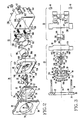
- the toggle switch 20 denotes an electrical toggle switch for two switch positions, which is composed of a contact module 22 and an actuator module 24.
- the elements of the toggle switch 20 described in more detail below can consist of suitable high-strength plastics or, if no electrical insulation is required, of suitable metals.
- parts subject to friction during the switching operation can be made of nylon, and the housing and other non-subject parts can be made of polycarbonate-based plastics.
- the toggle switch 20 is set up for mounting on a front panel 26 which has inner and outer sides or surfaces 28 and 30 and an opening 32 which extends between the sides 28 and 30.
- the toggle switch 20 is fastened to the inner side 28 of the front plate 26 by means of fastening means 34 which have first and second threaded columns 36 and 38, which are fastened to the inner side 28, and can be screwed onto the threaded columns 36 and 38 Have nuts 40 and 42.
- the fastening means 34 simultaneously fasten the contact module and the actuator module, the latter being clamped between the contact module 22 and the inner side 28 of the front plate 26.
- the elements of the actuator module 24 are also held in the desired position by means of the frictional connection effected by the fastening means 34, which simplifies the manufacture and assembly of the toggle switch 20.
- the actuator module 24 consists of a guide ring 44, an actuating lever 46 and a guide ring adapter 48.
- the guide ring 44 adapts the actuator module 24 to the front plate 26, while the guide ring adapter 48 adapts the actuator module 24 to the contact module 22.
- the guide ring 44 has a first and a second axial end 50 and 52 relative to a longitudinal axis 54 of the toggle switch 20, which is concentric with the opening 32 of the front plate 26.
- the guide ring 44 has a flange 56 lying in the middle between its two ends, a first and a second cylindrical projection 58 and 60, which extend from the flange 56 in the direction of the first and second axial Extend ends 50 and 52, and an opening 62 extending between the axial ends 50 and 52.
- the cylindrical extension 58 has a first and a second recess 64 and 66, respectively, which are arranged on opposite sides of the opening 62 and extend in the same direction.
- the recesses 64 and 66 have straight, parallel sides which end in cross section in a semicircular surface. As can be seen from FIG. 3, in the recess 64 the straight surfaces are designated 68 and 70 and the semicircular surface 72, the semicircular surface 72 having a central axis 73.
- the cylindrical extension 60 extends perpendicularly from the flange 56 by a predetermined length, designated 74, which is preferably equal to the thickness of the front plate 26; for example 3.2 mm.
- the extension 60 then borders on spherical surfaces 76 and 78, which are separated by the opening 62 and shallow recesses 80 and 82, which run perpendicular to the longitudinal axis 54.
- the opening 62 at the second axial end 52 has two separate flat surfaces 84 and 86, which are chamfered at an angle 88 of 30 degrees.
- the tapered surfaces end when they reach the flat recesses 80 and 82, the opening 62 progressively being defined towards the first axial end 50 by surfaces 90 and 92 running parallel to one another.
- the opening 62 begins at the flat recesses 80 and 82 and the flat surfaces 94 and 96 extending at an angle of 30 degrees to the longitudinal axis 54.
- the flat surfaces 94 and 96 end at one end from the longitudinal axis 54 from outward-facing sheets of short length.
- the arcuate surfaces 98 and 100 formed in this way adjoin flat surfaces 102 and 104 which run parallel to one another and extend to the first axial end 50 of the guide ring 44.
- the actuating lever 46 has a first and a second axial end 106 and 108, respectively.
- the first axial end 106 serves as an actuation cam and the second axial end 108 serves as a handle for the manually actuable switch 20.
- a first and a second pivot 110 and 112 extend from opposite sides of the actuation lever 46, lying on a common axis 114 , outward.
- the diameters of the pivot pins 110 and 112 are dimensioned such that they lie closely in the recesses 64 and 66, respectively, the recesses 64 and 66 serving as bearings for the pivoting movement of the actuating lever 46 about the axis 114.
- the Actuating lever 46 begins at the first axial end 106 with a radius of, for example, 1.6 mm, which merges into flat, parallel sides 116 and 118 which extend over a certain length towards the second axial end 108.
- the sides 116 and 118 meet flat surfaces 120 and 122, respectively, which are beveled outward at a certain angle, for example 105 degrees.
- the flat surfaces 120 and 122 meet arcuate surfaces 124 and 126, respectively, which have a certain radius, for example 7.9 mm.
- the arcuate surfaces 124 and 126 are immediately adjacent to the arcuate surfaces 98 and 100 after the installation of the operating lever 46 in the guide ring 44.
- the arcuate surfaces 124 and 126 meet flat, parallel surfaces 128 and 130, which extend to the second axial end 108 and merge into a radius of 3.2 mm, for example.
- the guide ring adapter 48 has fastening eyes in which holes 132 and 134 are arranged for receiving the threaded columns 36 and 38, respectively.
- the guide ring adapter 48 has a first and a second axial end 136 or 138 and a wall 140 arranged at the first axial end 136.
- the wall 140 has a surface 142 which delimits a circular opening lying coaxially to the longitudinal axis 54.
- the guide ring adapter 48 also has a surface 144 that defines a circular opening that begins at the second axial end 138 and extends to the wall 140.
- the opening defined by the surface 142 is dimensioned such that the actuating cam 106 of the actuating lever 46 can protrude through and pivot in a specific area.
- the opening defined by the surface 144 is dimensioned such that the cylindrical extension 58 of the guide ring 44 can be accommodated in a closely fitting but sliding manner.
- the second axial end 138 is recessed by the thickness of the flange 56 of the guide ring 44, thereby forming upper and lower lips 146 and 148, respectively.
- the distance of the lips 146 and 148 from one another are dimensioned such that the flange 56 can be pushed in tightly therebetween, a projection 150 located on the lip 148 engaging in a groove 152 or 154 provided on the flange 56, so that the guide ring 44 is aligned concentrically with the longitudinal axis 54 .
- the contact module 22 has a housing 156 with attachment eyes, in which holes 158 and 160 are provided for receiving the threaded columns 36 and 38 of the front plate 26, and fixed electrical contacts 162 and 164.
- the fixed electrical contacts can normally be open, closed, or one open and the other closed. In the exemplary embodiment, contact 162 may be closed and contact 164 may be open.
- the contact module 22 also has a contact carrier 166 with a first and a second axial end 168 and 170, electrical contacts 172 and 174 being arranged at the first axial end 168 and cooperating with the fixed contacts 162 and 164, respectively.
- the contact carrier 166 is guided in a straight line, movable along the longitudinal axis 54 within the housing 156 by means of ribs which engage in grooves.
- Compression springs 176 are arranged between the housing and the first axial end 168, which press the contact carrier 166 into a first axial limit position, which, as can be seen in more detail from the above-mentioned patent specification, is provided by contact of a leg 178 of the contact carrier 166 with a housing surface.
- a second axial basis is achieved after overcoming the spring force of the compression springs 176, the contact carrier 166 abutting against a wall part of the housing 156, as also shown in the above-mentioned patent.
- the second axial end 170 of the contact carrier 166 has a cylindrical recess 180, which extends inward from end 170 by a certain length.
- An axially extending groove 182 is provided in the wall which delimits the recess 180.
- a cam 184 shown in FIGS. 2, 3, 10 and 11 is arranged in the recess 180 of the contact carrier 166.
- Both the cam 184 and the actuating lever 46 are preferably made of nylon because this material is well suited for parts subject to dynamic friction.
- the cam 184 which is essentially cylindrical in shape, has a first and a second end 186 or 188, a recess 189 being provided at the second end 188.
- the diameter of the cam 184 is to be dimensioned such that it can be press-fit into the recess 180 of the contact carrier 166, the outer surface of the cam 184 having a rib 191 which engages in the groove 183 so that the cam 184 is precisely aligned becomes.
- the recess 189 is formed from a first and a second step 190 and 192 which extend inwards from the second axial end 188 and serve as a first and second time limit.
- the first and second stages 190 and 192 are connected by an inclined cam surface 194.
- grooves 196 and 198 are arranged which ensure secure positions of the actuating cam 106 of the actuating lever 46, so that when switching over it can be felt that the actuating lever 46 has changed from one position to the other .
- the depth of the recess 189 is chosen so that the springs 176 are only slightly compressed when the actuating cam 106 is engaged in the groove 198 adjacent to the step 192.
- the spring force is dimensioned so that the actuating cam 106 is held in the groove 198, whereby a completely closed state of the normally closed contacts and the desired distance between the normally open contacts is ensured. If the operating lever 46 is moved such that the Actuating cam 106 is guided over the cam surface 194 to the groove 196 adjacent to the first lateral step 190, the contact carrier 166 is pushed against the compression springs 176 into a position in which the normally closed contact is completely open and the normally open contact is completely closed. The pressure exerted by the compression springs 176 holds the actuating cam 106 of the actuating lever 46 in the groove 196, so that the position of the switch 20 set by hand is retained.
- the manufacture and assembly of the switch 20 is facilitated by the fastening arrangement provided, since the switch is mounted on a front plate 26, by means of which the actuating elements of the actuating element module 24 are held in the desired relative position to one another.
- the elements of actuator module 24 can be frictionally assembled, with guide ring 44 and guide adapter 48 cooperating to form a bearing for pivots 110 and 112 which, when actuator module 24 is fixed by fasteners 34 is clamped between the front plate 26 and the contact module 22, is finally fixed.
- the handle end 108 of the actuating lever 46 is inserted into the opening 62 of the guide ring 44 until the pivot pins 110 and 112 are inserted into the recesses 64 and 66 of the guide ring 44.
- Spherical surfaces 76 and 78 protect handle end 108 from accidental actuation, with inclined surfaces 84 and 86 and flat recesses 80 and 82 leaving sufficient room for manual actuation of handle end 108.
- the flat surfaces 94 and 96 provide a firm stop for the handle end 108 because its sides 128 and 130 abut against the surfaces 94 and 96 when pivoted, which limits the range of the pivoting movement.
- the guide ring adapter 48 is placed on the guide ring 44 pushed by inserting the cylindrical extension 58 into the opening of the guide ring adapter 48 defined by the surface 144.
- the dimensions of the parts to be assembled are such that the elements of the actuator module 24 are held in the assembled position by friction until the rear wall 140 of the guide ring adapter 48 is pressed against the pivot pins 110 and 112 of the actuating lever 46.
- the actuator module 24 is then assembled with the contact module 22 such that projections 200 attached to the housing 156 are snugly inserted into openings of the first axial end 136 of the guide ring adapter 48, the actuator and contact modules being held in this position by friction.
- the tension of the compression springs 176 exerts pressure on the guide ring 44, so that the latter has the tendency to move forward slightly with the actuating lever 46.
- the elements of the actuator module 24 remain coupled even if the guide ring 44 and the guide ring adapter 48 are not firmly pressed together.
- pressure is exerted on the actuating lever 46 so that it is firmly seated, regardless of the switch position.
- the final assembly is done by pushing the threaded column 36 through the aligning holes 132 and 158, and the threaded column 38 through the aligning holes 134 and 160 of the guide ring adapter 48 and the housing 156, with the cylindrical extension 60 of the guide ring 44 into the opening 32 of the front panel 26 is fitted.
- the actuator module 24 is firmly clamped between the inner surface 28 of the front plate 26 and the contact module 22, the flange 56 of the guide ring 44 being pressed firmly against the guide ring adapter 48, so that the Bearing for the pivot pins 110 and 112 is finally fixed by the interaction of the surfaces of the guide ring 44 and the guide ring adapter 48.
- the fastening means 34 thus also hold the switch 20 on the front plate 26.
Landscapes
- Push-Button Switches (AREA)
- Tumbler Switches (AREA)
- Switches With Compound Operations (AREA)
- Mechanisms For Operating Contacts (AREA)
- Valve-Gear Or Valve Arrangements (AREA)
- Valve Device For Special Equipments (AREA)
- Rotary Switch, Piano Key Switch, And Lever Switch (AREA)
Applications Claiming Priority (2)
| Application Number | Priority Date | Filing Date | Title |
|---|---|---|---|
| US262850 | 1988-10-26 | ||
| US07/262,850 US4847458A (en) | 1988-10-26 | 1988-10-26 | Electric switch |
Publications (3)
| Publication Number | Publication Date |
|---|---|
| EP0365909A2 true EP0365909A2 (fr) | 1990-05-02 |
| EP0365909A3 EP0365909A3 (fr) | 1991-09-04 |
| EP0365909B1 EP0365909B1 (fr) | 1995-04-05 |
Family
ID=22999333
Family Applications (1)
| Application Number | Title | Priority Date | Filing Date |
|---|---|---|---|
| EP89118763A Expired - Lifetime EP0365909B1 (fr) | 1988-10-26 | 1989-10-10 | Module à touche avec bascule de commande |
Country Status (7)
| Country | Link |
|---|---|
| US (1) | US4847458A (fr) |
| EP (1) | EP0365909B1 (fr) |
| JP (1) | JPH02181324A (fr) |
| AT (1) | ATE120879T1 (fr) |
| CA (1) | CA2001604C (fr) |
| DE (1) | DE58909160D1 (fr) |
| ES (1) | ES2073420T3 (fr) |
Families Citing this family (1)
| Publication number | Priority date | Publication date | Assignee | Title |
|---|---|---|---|---|
| US8946576B2 (en) * | 2012-11-19 | 2015-02-03 | Pass & Seymour, Inc. | Quiet electromechanical switch device |
Family Cites Families (5)
| Publication number | Priority date | Publication date | Assignee | Title |
|---|---|---|---|---|
| US2133545A (en) * | 1936-06-11 | 1938-10-18 | Cutler Hammer Inc | Electric switch |
| US2366474A (en) * | 1942-07-25 | 1945-01-02 | Arrow Hart & Hegeman Electric | Slow break electric switch |
| US3501599A (en) * | 1968-12-19 | 1970-03-17 | Molex Products Co | Electrical slide switch with prewired terminals |
| US4400603A (en) * | 1981-07-23 | 1983-08-23 | Westinghouse Electric Corp. | Electrical switch for alternating current |
| US4689456A (en) * | 1986-04-30 | 1987-08-25 | Adams Elevator Equipment Company | Key switch having cooperable cams which translate rotary motion to rectilinear |
-
1988
- 1988-10-26 US US07/262,850 patent/US4847458A/en not_active Expired - Lifetime
-
1989
- 1989-10-10 EP EP89118763A patent/EP0365909B1/fr not_active Expired - Lifetime
- 1989-10-10 DE DE58909160T patent/DE58909160D1/de not_active Expired - Fee Related
- 1989-10-10 AT AT89118763T patent/ATE120879T1/de not_active IP Right Cessation
- 1989-10-10 ES ES89118763T patent/ES2073420T3/es not_active Expired - Lifetime
- 1989-10-25 JP JP1278339A patent/JPH02181324A/ja active Pending
- 1989-10-26 CA CA002001604A patent/CA2001604C/fr not_active Expired - Lifetime
Also Published As
| Publication number | Publication date |
|---|---|
| DE58909160D1 (de) | 1995-05-11 |
| ATE120879T1 (de) | 1995-04-15 |
| CA2001604C (fr) | 2000-12-12 |
| ES2073420T3 (es) | 1995-08-16 |
| EP0365909B1 (fr) | 1995-04-05 |
| CA2001604A1 (fr) | 1990-04-26 |
| JPH02181324A (ja) | 1990-07-16 |
| US4847458A (en) | 1989-07-11 |
| EP0365909A3 (fr) | 1991-09-04 |
Similar Documents
| Publication | Publication Date | Title |
|---|---|---|
| DE2706463A1 (de) | Druckknopfschalter fuer elektrische rechner u.dgl. | |
| DE1959155C3 (de) | Elektrischer Schnappschalter | |
| DE2730597A1 (de) | Elektrischer schalter | |
| DE2416969C2 (de) | Druckknopfschalter | |
| EP0965699B1 (fr) | Dispositif pour le montage coulissant d'un article, en particulier une pomme de douche sur une barre de support | |
| DE6905921U (de) | Druckknopfschalteranordnung | |
| EP0365909B1 (fr) | Module à touche avec bascule de commande | |
| CH652269A5 (en) | Quick mounting base made of plastic, for fixing an electrical device or printed-circuit board | |
| DE3442173A1 (de) | Elektrischer schalter gedrungener bauart | |
| DE4240218C2 (de) | Schaltvorrichtung | |
| DE4439008A1 (de) | Elektrischer Tastschalter | |
| DE69501990T2 (de) | Drehschalter mit verriegelbarer Position | |
| DE3620105C1 (en) | Electrical contact switch | |
| DE3107316A1 (de) | "schiebeschalter" | |
| DE8611988U1 (de) | Befestigungsvorrichtung vom Druckknopftyp | |
| DE4323083A1 (de) | Multifunktionsschalter zur Betätigung einer ersten und zweiten elektrischen Einrichtung | |
| DE2843891A1 (de) | Elektrisches installationsgeraet | |
| DE2741219B2 (de) | Schaltervorrichtung | |
| DE2827854C2 (de) | Elektrischer Wippenschalter | |
| EP0421321B1 (fr) | Dispositif de fixation d'un support d'accessoire de salle de bain | |
| CH679094A5 (fr) | ||
| DE2558567B2 (de) | Schiebeschalter | |
| EP1411845B1 (fr) | Instrument medical comportant deux parties ainsi qu'un dispositif de liaison destine a les relier | |
| DE3115793A1 (de) | Elektrischer schalter | |
| DE3324253A1 (de) | Tastenschalter |
Legal Events
| Date | Code | Title | Description |
|---|---|---|---|
| PUAI | Public reference made under article 153(3) epc to a published international application that has entered the european phase |
Free format text: ORIGINAL CODE: 0009012 |
|
| AK | Designated contracting states |
Kind code of ref document: A2 Designated state(s): AT CH DE ES FR GB IT LI |
|
| PUAL | Search report despatched |
Free format text: ORIGINAL CODE: 0009013 |
|
| AK | Designated contracting states |
Kind code of ref document: A3 Designated state(s): AT CH DE ES FR GB IT LI |
|
| 17P | Request for examination filed |
Effective date: 19920224 |
|
| 17Q | First examination report despatched |
Effective date: 19940120 |
|
| GRAA | (expected) grant |
Free format text: ORIGINAL CODE: 0009210 |
|
| AK | Designated contracting states |
Kind code of ref document: B1 Designated state(s): AT CH DE ES FR GB IT LI |
|
| REF | Corresponds to: |
Ref document number: 120879 Country of ref document: AT Date of ref document: 19950415 Kind code of ref document: T |
|
| REF | Corresponds to: |
Ref document number: 58909160 Country of ref document: DE Date of ref document: 19950511 |
|
| ET | Fr: translation filed | ||
| GBT | Gb: translation of ep patent filed (gb section 77(6)(a)/1977) |
Effective date: 19950515 |
|
| ITF | It: translation for a ep patent filed | ||
| REG | Reference to a national code |
Ref country code: ES Ref legal event code: FG2A Ref document number: 2073420 Country of ref document: ES Kind code of ref document: T3 |
|
| PGFP | Annual fee paid to national office [announced via postgrant information from national office to epo] |
Ref country code: GB Payment date: 19950926 Year of fee payment: 7 |
|
| PGFP | Annual fee paid to national office [announced via postgrant information from national office to epo] |
Ref country code: DE Payment date: 19950929 Year of fee payment: 7 |
|
| PGFP | Annual fee paid to national office [announced via postgrant information from national office to epo] |
Ref country code: AT Payment date: 19951002 Year of fee payment: 7 |
|
| PGFP | Annual fee paid to national office [announced via postgrant information from national office to epo] |
Ref country code: ES Payment date: 19951003 Year of fee payment: 7 |
|
| PGFP | Annual fee paid to national office [announced via postgrant information from national office to epo] |
Ref country code: FR Payment date: 19951004 Year of fee payment: 7 |
|
| PG25 | Lapsed in a contracting state [announced via postgrant information from national office to epo] |
Ref country code: LI Effective date: 19951031 Ref country code: CH Effective date: 19951031 |
|
| PLBE | No opposition filed within time limit |
Free format text: ORIGINAL CODE: 0009261 |
|
| STAA | Information on the status of an ep patent application or granted ep patent |
Free format text: STATUS: NO OPPOSITION FILED WITHIN TIME LIMIT |
|
| 26N | No opposition filed | ||
| REG | Reference to a national code |
Ref country code: CH Ref legal event code: PL |
|
| PG25 | Lapsed in a contracting state [announced via postgrant information from national office to epo] |
Ref country code: GB Effective date: 19961010 Ref country code: AT Effective date: 19961010 |
|
| PG25 | Lapsed in a contracting state [announced via postgrant information from national office to epo] |
Ref country code: ES Free format text: LAPSE BECAUSE OF EXPIRATION OF PROTECTION Effective date: 19961011 |
|
| GBPC | Gb: european patent ceased through non-payment of renewal fee |
Effective date: 19961010 |
|
| PG25 | Lapsed in a contracting state [announced via postgrant information from national office to epo] |
Ref country code: FR Effective date: 19970630 |
|
| PG25 | Lapsed in a contracting state [announced via postgrant information from national office to epo] |
Ref country code: DE Effective date: 19970701 |
|
| REG | Reference to a national code |
Ref country code: FR Ref legal event code: ST |
|
| REG | Reference to a national code |
Ref country code: ES Ref legal event code: FD2A Effective date: 19990601 |
|
| PG25 | Lapsed in a contracting state [announced via postgrant information from national office to epo] |
Ref country code: IT Free format text: LAPSE BECAUSE OF NON-PAYMENT OF DUE FEES;WARNING: LAPSES OF ITALIAN PATENTS WITH EFFECTIVE DATE BEFORE 2007 MAY HAVE OCCURRED AT ANY TIME BEFORE 2007. THE CORRECT EFFECTIVE DATE MAY BE DIFFERENT FROM THE ONE RECORDED. Effective date: 20051010 |