EP0365959B1 - Procédé et dispositif pour la détermination approximative d'une vitesse de rotation - Google Patents
Procédé et dispositif pour la détermination approximative d'une vitesse de rotation Download PDFInfo
- Publication number
- EP0365959B1 EP0365959B1 EP89119146A EP89119146A EP0365959B1 EP 0365959 B1 EP0365959 B1 EP 0365959B1 EP 89119146 A EP89119146 A EP 89119146A EP 89119146 A EP89119146 A EP 89119146A EP 0365959 B1 EP0365959 B1 EP 0365959B1
- Authority
- EP
- European Patent Office
- Prior art keywords
- approx
- speed
- rotational speed
- values
- time period
- Prior art date
- Legal status (The legal status is an assumption and is not a legal conclusion. Google has not performed a legal analysis and makes no representation as to the accuracy of the status listed.)
- Expired - Lifetime
Links
Images


Classifications
-
- G—PHYSICS
- G01—MEASURING; TESTING
- G01P—MEASURING LINEAR OR ANGULAR SPEED, ACCELERATION, DECELERATION, OR SHOCK; INDICATING PRESENCE, ABSENCE, OR DIRECTION, OF MOVEMENT
- G01P11/00—Measuring average value of speed
Definitions
- This invention relates generally to a method and system for determining rotational speed of a rotating member such as a vehicular transmission input shaft and more particularly to a method and system for determining approximate rotational speed of a rotating member whose rotation is changing with time.
- US-A-3 182 503 disclose a circuitry to obtain the mean rotational speed of an anemometer. To this end the shaft of the anemometer is coupled to a device that transforms the rotation into a current being proportional to the speed. This current signal is supplied into a low pass filter in the form of an integrator.
- the integrator comprises a differential amplifier which is fed back to its inverted input via a parallel arrangement including a capacitor, a fixed resistor and an adjustable resistor.
- this low pass filter or what is equivalent its cut off frequency depends on the value of the capacitor and the resistance of both resistors. Therefore, it is necessary to adjust the resistance for calibrating the arrangement. If the adjustment is not stable then the cut off frequency will change and as a consequence the time period which is taken into account to obtain the mean value changes also.
- Rotational speed of a rotating member however is frequently not constant and may vary with time for a variety of reasons. Such variations in rotational speed (often characterized as “loping” or “oscillations") present a real problem in determining a means or approximate speed for visual and more particularly for control purposes.
- Variations in speed relative time results in the problem of having to determine an approximate or mean rotational speed from a plurality of discrete rotational speed values within a predetermined time period.
- the present invention establishes conditions by which the above equation is reduced to a family relatively simple linear equations for determining approximate rotational speed of a rotating member whose rotational speed may not be uniform and which can be rapidly determined by microprocessors well known to those skilled in the art.
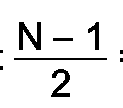
- N-1 2 is the even number of speed measurements on opposite sides of an orthogonal axis whose origin is located at the middle value for t n and whose ordinate is speed whose abscissa is time and for which T n has the value of zero at the origin with values of T n having opposite signs on opposite sides of the ordinate and the values of s n positive in all quadrants.
- FIGURES 1 and 2 where, in FIGURE 1, five speed values (s o , s1, s2, s3 and s4) are respectively decreasing from left to right over time period T.
- T2 at the origin is assigned the value of zero and that the values for T n to the left of the ordinate (speed) are negative and to the right of the ordinate (speed) are positive and that the increments of time along the abscissa are substantially equivalent.
- N 5 which is an odd whole integer greater than 1 and that N-1 2 equals 2 which is an even integer equal to the number of speed measurements taken on opposite sides of the (speed) ordinate.
- FIGURE 2 is a graph of speed measurements versus time that are respectively increasing from right to left over time period T.
- FIGURE 3 a system is provided for approximating rotational speed of a rotating shaft 2 such as an input shaft of a vehicular transmission.
- the system includes a speed sensor 4 and processor 6.
- Speed sensor 4 may be any type of sensor able to sense and transmit a signal 5 of rotational speed values (s o , s1, s2, s37-8s n ) of shaft 2 within a predetermined time period T which may be in the order of micro-seconds. Hall-Effect magnetic sensors are but one way to measure rotational speed known to those skilled in the art.
- Signal 5 is received by processor 6 which is of the type well known to those skilled in the art operable to receive signal 5 and select certain values therefrom and perform the simple linear arithmetic calculations shown in FIGURE 3.
- processor 6 is shown in FIGURE 3 as being capable of performing six calculations, such as for illustrative purposes for it may process and provide only one or any combination of output signals s3, s3′, s5, s5′, s7 and s7′ which may be utilized as signal for controlling shifting of vehicular transmission being driven by shaft 2.
- processor 6 is shown in FIGURE 3 as selecting certain speed values, such may be done by speed sensor 4 by selecting and transmitting only those rotational speed values for which processor 6 is adapted to make the particular linear calculations hereinbefore set forth.
Landscapes
- Physics & Mathematics (AREA)
- General Physics & Mathematics (AREA)
- Control Of Transmission Device (AREA)
Claims (18)
- Procédé linéaire de détermination de la vitesse de rotation moyenne approximative d'un organe rotatif, et procédé comprenant les étapes consistant à :(a) déterminer une équation en sélectionnant une valeur pour un paramètre N conformément à

sn représentant les mesures individuelles de vitesse possédant un signe positif et effectuées pendant un intervalle de temps T à des instants équidistants, s₀ étant considéré au début de l'intervalle de temps T et sN-1 à la fin de l'intervalle de temps T;(b) mesurer les valeurs sn de la vitesse de rotation de l'organe rotatif telles que définies lors de l'étape (a) et délivrer des signaux indicatifs de ces valeurs; et(c) déterminer S(approx.) par traitement des signaux de vitesse de l'étape (b) conformément à l'équation sélectionnée lors de l'étape (a). - Procédé suivant la revendication 1, incluant l'étape consistant à délivrer un signal correspondant à la valeur de S(approx.) déterminée lors de l'étape (c).
- Procédé selon la revendication 1, selon lequel N=3 et


- Procédé selon la revendication 1, selon lequel N=3 et


- Procédé selon la revendication 1, selon lequel N=5 et


- Procédé selon la revendication 1, selon lequel N=5 et


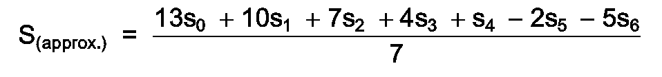
- Procédé selon la revendication 1, selon lequel N=7 et


- Procédé selon la revendication 1, selon lequel N=7 et
- Procédé selon la revendication 1, selon lequel l'organe est l'arbre d'un véhicule.
- Procédé selon la revendication 1, selon lequel l'arbre est un arbre d'entrée de transmission.
- Procédé selon la revendication 2, selon lequel le signal est un signal de commande utilisé par une transmission d'un véhicule.
- Système pour déterminer une vitesse de représentation approximative d'un organe rotatif, ledit système comprenant :
des moyens de détection de vitesse, lesdits moyens agissant de manière à mesurer et délivrer un signal indicatif de la vitesse de rotation de l'organe rotatif,
des moyens pour sélectionner trois valeurs (s₀ s₁, s₂) du signal de vitesse a des instants sensiblement équidistants au cours d'un intervalle de temps prédéterminé, et
des moyens pour traiter les valeurs de vitesse sélectionnées pour déterminer la vitesse de rotation approximative S(approx.) conformément à l'une des équations :

- Système pour déterminer la vitesse de rotation approximative d'un organe rotatif, ledit système comprenant :
des moyens de détection de vitesse, lesdits moyens agissant de manière à mesurer et délivrer un signal indicatif de la vitesse de rotation de l'organe rotatif,
des moyens pour sélectionner cinq valeurs (so, s₁, s₂, s₃, s₄) du signal de vitesse à des instants sensiblement équidistants au cours d'un intervalle de temps prédéterminé, et
des moyens pour traiter les valeurs de vitesse sélectionnées pour déterminer une vitesse de rotation approximative S(approx.) conformément a l'une des équations:

- Système pour déterminer une vitesse de rotation approximative d'un organe rotatif, ledit système comprenant :
des moyens de détection de vitesse, lesdits moyens agissant de manière à mesurer et délivrer un signal indicatif de la vitesse de rotation de l'organe rotatif,
des moyens pour sélectionner sept valeurs (so, s₁, s₂, s₃, s₄, s₅, s₆) du signal de vitesse à des instants sensiblement équidistants au cours d'un intervalle de temps prédéterminé, et
des moyens pour traiter les valeurs de vitesse sélectionnées pour déterminer la vitesse de rotation approximative S(approx.) selon l'une des équations :

- Système selon les revendications 12, 13 ou 14 comprenant des moyens pour délivrer un signal indicatif de S(approx.).
- Système selon les revendications 12, 13 ou 14, dans lequel l'organe est l'arbre d'un véhicule.
- Système selon la revendication 16, dans lequel l'arbre est un arbre d'entrée de transmission.
- Système selon la revendication 15, dans lequel le signal est un signal de commande utilisé par une transmission d'un véhicule.
Applications Claiming Priority (2)
| Application Number | Priority Date | Filing Date | Title |
|---|---|---|---|
| US07/261,448 US4959806A (en) | 1988-10-24 | 1988-10-24 | Approximated rotational speed signal for shifting transmission |
| US261448 | 1988-10-24 |
Publications (3)
| Publication Number | Publication Date |
|---|---|
| EP0365959A2 EP0365959A2 (fr) | 1990-05-02 |
| EP0365959A3 EP0365959A3 (fr) | 1991-10-09 |
| EP0365959B1 true EP0365959B1 (fr) | 1994-08-31 |
Family
ID=22993353
Family Applications (1)
| Application Number | Title | Priority Date | Filing Date |
|---|---|---|---|
| EP89119146A Expired - Lifetime EP0365959B1 (fr) | 1988-10-24 | 1989-10-14 | Procédé et dispositif pour la détermination approximative d'une vitesse de rotation |
Country Status (6)
| Country | Link |
|---|---|
| US (1) | US4959806A (fr) |
| EP (1) | EP0365959B1 (fr) |
| JP (1) | JPH02170057A (fr) |
| BR (1) | BR8905496A (fr) |
| CA (1) | CA1335459C (fr) |
| DE (1) | DE68917849T2 (fr) |
Families Citing this family (5)
| Publication number | Priority date | Publication date | Assignee | Title |
|---|---|---|---|---|
| US5411450A (en) * | 1993-04-01 | 1995-05-02 | Oshkosh Truck Corporation | Transit clutchless shifting of an auxiliary transmission |
| KR100369623B1 (ko) * | 1999-08-20 | 2003-01-29 | 남종현 | 스태미나 증진효과가 있는 천연차 및 그 제조방법 |
| DE602005012743D1 (de) * | 2004-01-29 | 2009-04-02 | Panasonic Corp | Verfahren und Vorrichtung zu Berechnung der Lenkwinkelgeschwindigkeit |
| US10173718B2 (en) * | 2013-07-19 | 2019-01-08 | Steering Solutions Ip Holding Corporation | Motor position filter for estimation of velocity using moving linear regression |
| US12155324B2 (en) * | 2022-09-04 | 2024-11-26 | Steering Solutions Ip Holding Corporation | Systems and methods for estimating motor velocity |
Family Cites Families (4)
| Publication number | Priority date | Publication date | Assignee | Title |
|---|---|---|---|---|
| US3182503A (en) * | 1962-02-12 | 1965-05-11 | Beckman & Whitley Inc | Meteorologic instrument |
| US4361060A (en) * | 1978-01-24 | 1982-11-30 | Smyth Robert Ralston | Mechanical automatic transmission |
| GB8418749D0 (en) * | 1984-07-23 | 1984-08-30 | Eaton Ltd | Semi-automatic transmission control |
| US4595896A (en) * | 1984-10-01 | 1986-06-17 | Siemens-Allis, Inc. | Molded case circuit breaker having a reinforced housing |
-
1988
- 1988-10-24 US US07/261,448 patent/US4959806A/en not_active Expired - Fee Related
-
1989
- 1989-09-29 CA CA000615244A patent/CA1335459C/fr not_active Expired - Fee Related
- 1989-10-14 DE DE68917849T patent/DE68917849T2/de not_active Expired - Fee Related
- 1989-10-14 EP EP89119146A patent/EP0365959B1/fr not_active Expired - Lifetime
- 1989-10-24 BR BR898905496A patent/BR8905496A/pt not_active IP Right Cessation
- 1989-10-24 JP JP1276958A patent/JPH02170057A/ja active Pending
Also Published As
| Publication number | Publication date |
|---|---|
| DE68917849T2 (de) | 1994-12-22 |
| JPH02170057A (ja) | 1990-06-29 |
| EP0365959A2 (fr) | 1990-05-02 |
| CA1335459C (fr) | 1995-05-02 |
| DE68917849D1 (de) | 1994-10-06 |
| BR8905496A (pt) | 1990-05-29 |
| US4959806A (en) | 1990-09-25 |
| EP0365959A3 (fr) | 1991-10-09 |
Similar Documents
| Publication | Publication Date | Title |
|---|---|---|
| EP0597899B1 (fr) | Capteur d'angle d'attaque, utilisant un rapport inverse de differences de pression | |
| US5977765A (en) | Speed, direction, and acceleration sensor for a rotating shaft having a rotor with teeth having unequal spacing | |
| US4535412A (en) | Drivetrain torque determination using torque converter characteristics | |
| US4799178A (en) | Method and apparatus for detecting rotational speed | |
| US6219607B1 (en) | Method for determining an intersection-torque in a driving line of a vehicle with an automatic transmission | |
| EP0365959B1 (fr) | Procédé et dispositif pour la détermination approximative d'une vitesse de rotation | |
| US5371460A (en) | Speed and direction sensor for a rotating shaft having a rotor with teeth of alternating widths | |
| US4885710A (en) | Method and apparatus for low speed estimation | |
| KR960706630A (ko) | 유량계내의 유체 유량의 현재값의 변화를 감시하는 방법 및 장치(method and device for monitoring changes in the current value of a fluid flow rate in a fluid meter) | |
| EP0529523A1 (fr) | Dispositif de commande pour plusieurs instruments d'indication | |
| EP0403055A2 (fr) | Méthode très efficace pour calculer la vitesse de rotation | |
| US4430606A (en) | Sheet feeding apparatus | |
| US5977764A (en) | Method to sense speed, direction and acceleration for a rotating shaft using a rotor with unequal tooth spacing | |
| US5400268A (en) | Vehicle speed determining device having means for accurate determination of zeroing of vehicle speed | |
| EP0505826B1 (fr) | Méthode de commander à un instrument de mesure | |
| EP1559636B1 (fr) | Procédé et dispositif de calcul de la vitesse angulaire d'un volant de direction | |
| EP0474362A2 (fr) | Appareil pour détecter la vitesse angulaire | |
| EP0689053A1 (fr) | Filtre pour détecteur de vitesse | |
| US4683427A (en) | Magnetic gear tooth separation detector | |
| GB2277596A (en) | Gauge with a moving indicator and adjustable sensitivity | |
| JPH11325103A (ja) | 過負荷検出方法および過負荷検出装置 | |
| JPH11326083A (ja) | 回転トルク測定方法および測定装置 | |
| JP2712253B2 (ja) | 車両用自動変速機の変速ショック測定装置 | |
| JP2778314B2 (ja) | 指示計器 | |
| EP1271003A2 (fr) | Méthode et procédure d'estimation d'une vitesse zéro |
Legal Events
| Date | Code | Title | Description |
|---|---|---|---|
| PUAI | Public reference made under article 153(3) epc to a published international application that has entered the european phase |
Free format text: ORIGINAL CODE: 0009012 |
|
| AK | Designated contracting states |
Kind code of ref document: A2 Designated state(s): DE FR GB IT SE |
|
| PUAL | Search report despatched |
Free format text: ORIGINAL CODE: 0009013 |
|
| AK | Designated contracting states |
Kind code of ref document: A3 Designated state(s): DE FR GB IT SE |
|
| 17P | Request for examination filed |
Effective date: 19911019 |
|
| 17Q | First examination report despatched |
Effective date: 19920903 |
|
| GRAA | (expected) grant |
Free format text: ORIGINAL CODE: 0009210 |
|
| AK | Designated contracting states |
Kind code of ref document: B1 Designated state(s): DE FR GB IT SE |
|
| REF | Corresponds to: |
Ref document number: 68917849 Country of ref document: DE Date of ref document: 19941006 |
|
| ITF | It: translation for a ep patent filed | ||
| ET | Fr: translation filed | ||
| EAL | Se: european patent in force in sweden |
Ref document number: 89119146.2 |
|
| PLBE | No opposition filed within time limit |
Free format text: ORIGINAL CODE: 0009261 |
|
| STAA | Information on the status of an ep patent application or granted ep patent |
Free format text: STATUS: NO OPPOSITION FILED WITHIN TIME LIMIT |
|
| 26N | No opposition filed | ||
| PGFP | Annual fee paid to national office [announced via postgrant information from national office to epo] |
Ref country code: GB Payment date: 19950918 Year of fee payment: 7 |
|
| PGFP | Annual fee paid to national office [announced via postgrant information from national office to epo] |
Ref country code: SE Payment date: 19950919 Year of fee payment: 7 |
|
| PGFP | Annual fee paid to national office [announced via postgrant information from national office to epo] |
Ref country code: FR Payment date: 19951020 Year of fee payment: 7 |
|
| PGFP | Annual fee paid to national office [announced via postgrant information from national office to epo] |
Ref country code: DE Payment date: 19951027 Year of fee payment: 7 |
|
| PG25 | Lapsed in a contracting state [announced via postgrant information from national office to epo] |
Ref country code: GB Effective date: 19961014 |
|
| PG25 | Lapsed in a contracting state [announced via postgrant information from national office to epo] |
Ref country code: SE Effective date: 19961015 |
|
| GBPC | Gb: european patent ceased through non-payment of renewal fee |
Effective date: 19961014 |
|
| PG25 | Lapsed in a contracting state [announced via postgrant information from national office to epo] |
Ref country code: FR Effective date: 19970630 |
|
| PG25 | Lapsed in a contracting state [announced via postgrant information from national office to epo] |
Ref country code: DE Effective date: 19970701 |
|
| EUG | Se: european patent has lapsed |
Ref document number: 89119146.2 |
|
| REG | Reference to a national code |
Ref country code: FR Ref legal event code: ST |
|
| PG25 | Lapsed in a contracting state [announced via postgrant information from national office to epo] |
Ref country code: IT Free format text: LAPSE BECAUSE OF NON-PAYMENT OF DUE FEES;WARNING: LAPSES OF ITALIAN PATENTS WITH EFFECTIVE DATE BEFORE 2007 MAY HAVE OCCURRED AT ANY TIME BEFORE 2007. THE CORRECT EFFECTIVE DATE MAY BE DIFFERENT FROM THE ONE RECORDED. Effective date: 20051014 |