EP0365964A1 - Strahlrohr - Google Patents
Strahlrohr Download PDFInfo
- Publication number
- EP0365964A1 EP0365964A1 EP89119169A EP89119169A EP0365964A1 EP 0365964 A1 EP0365964 A1 EP 0365964A1 EP 89119169 A EP89119169 A EP 89119169A EP 89119169 A EP89119169 A EP 89119169A EP 0365964 A1 EP0365964 A1 EP 0365964A1
- Authority
- EP
- European Patent Office
- Prior art keywords
- jet pipe
- section
- ring
- pipe according
- flange
- Prior art date
- Legal status (The legal status is an assumption and is not a legal conclusion. Google has not performed a legal analysis and makes no representation as to the accuracy of the status listed.)
- Granted
Links
- 238000011144 upstream manufacturing Methods 0.000 claims 1
- XLYOFNOQVPJJNP-UHFFFAOYSA-N water Substances O XLYOFNOQVPJJNP-UHFFFAOYSA-N 0.000 description 7
- 239000000463 material Substances 0.000 description 2
- 238000011161 development Methods 0.000 description 1
- 230000018109 developmental process Effects 0.000 description 1
- 239000012530 fluid Substances 0.000 description 1
- 238000012423 maintenance Methods 0.000 description 1
- 239000000203 mixture Substances 0.000 description 1
- 239000004576 sand Substances 0.000 description 1
Images


Classifications
-
- F—MECHANICAL ENGINEERING; LIGHTING; HEATING; WEAPONS; BLASTING
- F04—POSITIVE - DISPLACEMENT MACHINES FOR LIQUIDS; PUMPS FOR LIQUIDS OR ELASTIC FLUIDS
- F04F—PUMPING OF FLUID BY DIRECT CONTACT OF ANOTHER FLUID OR BY USING INERTIA OF FLUID TO BE PUMPED; SIPHONS
- F04F5/00—Jet pumps, i.e. devices in which flow is induced by pressure drop caused by velocity of another fluid flow
- F04F5/02—Jet pumps, i.e. devices in which flow is induced by pressure drop caused by velocity of another fluid flow the inducing fluid being liquid
- F04F5/10—Jet pumps, i.e. devices in which flow is induced by pressure drop caused by velocity of another fluid flow the inducing fluid being liquid displacing liquids, e.g. containing solids, or liquids and elastic fluids
- F04F5/12—Jet pumps, i.e. devices in which flow is induced by pressure drop caused by velocity of another fluid flow the inducing fluid being liquid displacing liquids, e.g. containing solids, or liquids and elastic fluids of multi-stage type
-
- F—MECHANICAL ENGINEERING; LIGHTING; HEATING; WEAPONS; BLASTING
- F04—POSITIVE - DISPLACEMENT MACHINES FOR LIQUIDS; PUMPS FOR LIQUIDS OR ELASTIC FLUIDS
- F04F—PUMPING OF FLUID BY DIRECT CONTACT OF ANOTHER FLUID OR BY USING INERTIA OF FLUID TO BE PUMPED; SIPHONS
- F04F5/00—Jet pumps, i.e. devices in which flow is induced by pressure drop caused by velocity of another fluid flow
- F04F5/02—Jet pumps, i.e. devices in which flow is induced by pressure drop caused by velocity of another fluid flow the inducing fluid being liquid
- F04F5/10—Jet pumps, i.e. devices in which flow is induced by pressure drop caused by velocity of another fluid flow the inducing fluid being liquid displacing liquids, e.g. containing solids, or liquids and elastic fluids
-
- F—MECHANICAL ENGINEERING; LIGHTING; HEATING; WEAPONS; BLASTING
- F04—POSITIVE - DISPLACEMENT MACHINES FOR LIQUIDS; PUMPS FOR LIQUIDS OR ELASTIC FLUIDS
- F04F—PUMPING OF FLUID BY DIRECT CONTACT OF ANOTHER FLUID OR BY USING INERTIA OF FLUID TO BE PUMPED; SIPHONS
- F04F5/00—Jet pumps, i.e. devices in which flow is induced by pressure drop caused by velocity of another fluid flow
- F04F5/44—Component parts, details, or accessories not provided for in, or of interest apart from, groups F04F5/02 - F04F5/42
- F04F5/46—Arrangements of nozzles
- F04F5/466—Arrangements of nozzles with a plurality of nozzles arranged in parallel
-
- F—MECHANICAL ENGINEERING; LIGHTING; HEATING; WEAPONS; BLASTING
- F04—POSITIVE - DISPLACEMENT MACHINES FOR LIQUIDS; PUMPS FOR LIQUIDS OR ELASTIC FLUIDS
- F04F—PUMPING OF FLUID BY DIRECT CONTACT OF ANOTHER FLUID OR BY USING INERTIA OF FLUID TO BE PUMPED; SIPHONS
- F04F5/00—Jet pumps, i.e. devices in which flow is induced by pressure drop caused by velocity of another fluid flow
- F04F5/44—Component parts, details, or accessories not provided for in, or of interest apart from, groups F04F5/02 - F04F5/42
- F04F5/46—Arrangements of nozzles
- F04F5/467—Arrangements of nozzles with a plurality of nozzles arranged in series
Definitions
- the invention relates to a jet pipe according to the preamble of claim 1.
- Such a jet pipe is known from DE-PS 21 50 711.
- the section adjoining the entrance and the conical pipe section are connected to one another by screws.
- water under high pressure is fed in via the feed pipe and enters the pipe interior via the outlet openings in the direction of a conical jacket.
- a sand or soil-water mixture is sucked in on the inlet side and passed through the water cone jacket.
- a turbulence occurs, which leads to the conical section and the area having the outlet openings being subject to severe wear;
- two such jet pipes are to be cascaded in series, an exchange of worn parts leads to considerable downtimes.
- a multi-stage jet pump is known from DD 153 905, in which, however, the section following a diffuser is cylindrical or divergent. The individual steps can be connected to each other by screws.
- a multi-stage jet pump is known from US Pat. No. 2,396,290, in which the sections adjoining the diffuser are designed to be divergent or cylindrical. Individual sections of the device can be connected to one another by screwing.
- the object of the invention is to design such a jet pipe, in which the wearing parts are easy to replace.
- the jet pipe should be designed so that the wear is additionally reduced.
- the jet pipe 1 has a section 3 which can be connected to a supply line 2 for supplying a medium to be sucked in, a jet pipe housing 4 and a conical pipe section 5 which runs inside the latter.
- the section 3 is designed as a ring 6. It has a feed connection 7 which can be connected to a line which supplies a pressurized fluid medium and in particular water. Furthermore, outlet nozzles 9 are provided on a surface 8 extending into the interior of the tube and inclined against the tube axis in the circumferential direction, the axes of which are oriented such that water emerging from them to a common axial point 10 flows inside the tube and thus forms a conical water jacket 11. The outlet nozzles and the supply nozzle are connected to one another via a channel 12 which extends in the ring in the circumferential direction.
- the jet pipe housing 4 has a first connection 13 on the input side and an output connection 14 on the output side. Inside, the two nozzles are designed so that the conical tube section 5 can be inserted into the jet pipe housing 4 and is held coaxially by the two nozzles.
- the ring 6 On the input side, the ring 6 is flanged coaxially by means of screws via a second annular flange 15 to be fitted on the outside.
- the feed line is connected to section 3 via a further flange 16.
- the outlet-side flange 14 of the jet pipe section 16 arranged in front of it serves to mount the ring 6 belonging to the jet pipe section 17.
- the conical tube section 5 is designed such that its end 24 on the outlet side extends so far into section 3 of the subsequent jet tube section that the outlet nozzles 9 are covered as seen in a radial projection. This prevents the nozzles from being ground down and destroyed by the material passed through them.
- a corresponding ring insert not shown, corresponding in shape to the end of the conical pipe section, is used, which covers the nozzles there. It is also possible instead to have the end of the feed line 2 protruding into the interior so far that the material sucked in does not swirl directly past the nozzles.
- the jet pipe comprises a guide frame 18 with two side rails.
- the jet pipe housing and the ring 6 have pairs of wheels 21, 22; 23 on. With the help of these pairs of wheels, it is possible, in order to replace a conical tube section 5, to simply remove the ring 6 after loosening flange screws and to remove and replace the tube section 5. In the same way, maintenance work can optionally be carried out on the outlet nozzles 9 in a simple manner.
- water was supplied in each case via the supply nozzle 7.
- steam via one of the supply ports, if desired, for better solution of certain components.
- a ring 25 forming the free lip 24 can also be provided on the inlet side between the feed line 2 and the ring 6, which like the inwardly extended feed line 2 ensures that the nozzles 9 are not damaged .
Landscapes
- Engineering & Computer Science (AREA)
- Physics & Mathematics (AREA)
- Fluid Mechanics (AREA)
- Mechanical Engineering (AREA)
- General Engineering & Computer Science (AREA)
- Jet Pumps And Other Pumps (AREA)
- Surgical Instruments (AREA)
- Percussion Or Vibration Massage (AREA)
- Mechanical Treatment Of Semiconductor (AREA)
- Load-Engaging Elements For Cranes (AREA)
- Rigid Pipes And Flexible Pipes (AREA)
- Cleaning In General (AREA)
Abstract
Description
- Die Erfindung betrifft ein Strahlrohr nach dem Oberbegriff des Patentanspruches 1.
- Ein derartiges Strahlrohr ist aus der DE-PS 21 50 711 bekannt. Bei diesem sind der an den Eingang anschließende Abschnitt und der kegelförmige Rohrabschnitt durch Schrauben miteinander verbunden. Beim Einsatz eines solchen Strahlrohres wird über den Zuführstutzen unter hohem Druck stehendes Wasser zugeführt, welches über die Austrittsöffnungen in Richtung eines Kegelmantels in das Rohrinnere eintritt. Dadurch wird eingangsseitig ein Sand- bzw. Erd-Wasser-Gemisch angesaugt und durch den Wasserkegelmantel hindurchgeführt. Dabei tritt eine Verwirbelung ein, die dazu führt, daß der kegelförmige Abschnitt und der die Austrittsöffnungen aufweisende Bereich einer starken Abnutzung unterliegen; insbesondere dann, wenn zwei derartige Strahlrohre kaskadenartig hintereinander geschaltet werden sollen, führt ein Austausch verschlissener Teile zu erheblichen Ausfallzeiten.
- Aus der DD 153 905 ist eine mehrstufige Strahlpumpe bekannt, bei der allerdings der jeweils auf einen Diffusor folgende Abschnitt zylindrisch bzw. divergent ausgebildet ist. Die einzelnen Stufen sind durch Schrauben miteinander verbindbar. Aus der US-PS 2 396 290 ist eine mehrstufige Strahlpumpe bekannt, bei der die an dem Diffusor anschließenden Abschnitte divergent bzw. zylindrisch ausgebildet sind. Einzelne Abschnitte der Vorrichtung sind durch Verschrauben miteinander verbindbar.
- Aufgabe der Erfindung ist es, ein derartiges Strahlrohr auszubilden, bei dem die Verschleißteile einfach auswechselbar sind. Bevorzugt soll das Strahlrohr so ausgebildet werden, daß zusätzlich davon der Verschleiß verringert wird.
- Diese Aufgabe wird durch ein in Patentanspruch 1 gekennzeichnetes Strahlrohr gelöst.
- Weiterbildungen der Erfindung sind in den Unteransprüchen gekennzeichnet.
- Weitere Merkmale und Zweckmäßigkeiten der Erfindung ergeben sich aus der Beschreibung eines Ausführungsbeispieles anhand der Figuren. Von den Figuren zeigen:
- Fig. 1 einen Schnitt durch ein Strahlrohr mit zwei kaskadenartig hintereinander angeordneten Strahlrohrabschnitten;
- Fig. 2 eine Seitenansicht eines Strahlrohres mit explosionsartig auseinandergezogenen Teilen;
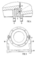
- Fig. 3 eine Ansicht des in Fig. 2 gezeigten Strahlrohres von der Eingangsseite her; und
- Fig. 4 ein Detail aus Fig. 1.
- Das Strahlrohr 1 weist einen mit einer Zufuhrleitung 2 zum Zuführen eines anzusaugenden Mediums verbindbaren Abschnitt 3, ein Strahlrohrgehäuse 4 und einen in dessen Innerem verlaufenden kegelförmigen Rohrabschnitt 5 auf.
- Der Abschnitt 3 ist als Ring 6 ausgebildet. Er weist einen mit einer ein unter Druck stehendes Fluidmedium und insbesondere Wasser zuführenden Leitung verbindbaren Zufuhrstutzen 7 auf. Ferner sind auf einer sich in das Rohrinnere erstrekkenden und gegen die Rohrachse geneigten Fläche 8 in Umfangsrichtung gegeneinander versetzt angeordnete Austrittsdüsen 9 vorgesehen, deren Achsen so ausgerichtet sind, daß aus ihnen austretendes Wasser zu einem gemeinsamen axialen Punkt 10 im Rohrinneren fließt und damit einen kegelförmigen Wassermantel 11 bildet. Die Austrittsdüsen und der Zufuhrstutzen sind über einen sich in dem Ring in Umfangsrichtung erstrekkenden Kanal 12 miteinander verbunden.
- Das Strahlrohrgehäuse 4 weist eingangsseitig einen ersten Stutzen 13 und ausgangsseitig einen Ausgangsstutzen 14 auf. Im Inneren sind die beiden Stutzen so ausgebildet, daß der kegelförmige Rohrabschnitt 5 in das Strahlrohrgehäuse 4 einschiebbar ist und von den beiden Stutzen koaxial gehalten wird. Eingangsseitig wird der Ring 6 über einen außen anzusetzenden zweiten ringförmigen Flansch 15 mittels Schrauben koaxial angeflanscht. Über einen weiteren Flansch 16 wird die Zufuhrleitung mit dem Abschnitt 3 verbunden.
- Bei der in Fig. 2 gezeigten Ausführungsform, bei der zwei Strahlrohrabschnitte 16 und 17 hintereinander angeordnet sind, dient zum Montieren des zu dem Strahlrohrabschnitt 17 gehörenden Ringes 6 der ausgangsseitige Flansch 14 des vor diesem angeordneten Strahlrohrabschnittes 16.
- Der kegelförmige Rohrabschnitt 5 ist so ausgebildet, daß sein ausgangsseitiges Ende 24 sich so weit in den Abschnitt 3 des nachfolgenden Strahlrohrabschnittes hinein erstreckt, daß in radialer Projektion gesehen die Austrittsdüsen 9 abgedeckt sind. Dadurch wird verhindert, daß durch das hindurchgeführte Material die Düsen abgeschliffen und zerstört werden. An der Eingangsseite des ersten Strahlrohrabschnittes wird ein entsprechender, nicht gezeigter, in seiner Form dem Ende des kegelförmigen Rohrabschnittes entsprechender Ringeinsatz eingesetzt, der die dortigen Düsen überdeckt. Es ist auch möglich, stattdessen das in das Innere hineinragende Ende der Zufuhrleitung 2 so weit hineinragen zu lassen, daß das eingesaugte Material nicht direkt an den Düsen vorbeiwirbelt.
- Wie insbesondere aus den Figuren 2 und 3 ersichtlich ist, umfaßt das Strahlrohr ein Führungsgestell 18 mit zwei seitlichen Schienen. Das Strahlrohrgehäuse und der Ring 6 weisen auf beiden Seiten angeordnete Räderpaare 21, 22; 23 auf. Mit Hilfe dieser Räderpaare ist es möglich, zum Auswechseln eines kegelförmigen Rohrabschnittes 5 auf einfache Weise den Ring 6 nach Lösen von Flanschschrauben wegzufahren und den Rohrabschnitt 5 herauszunehmen und auszutauschen. In gleicher Weise können auf einfache Weise ggf. Wartungsarbeiten an den Austrittsdüsen 9 vorgenommen werden.
- In dem oben beschriebenen Ausführungsbeispiel wurde über die Zufuhrstutzen 7 jeweils Wasser zugeführt. Es ist aber auch möglich, stattdessen über einen der Zufuhrstutzen gewünschtenfalls Dampf zur besseren Lösung bestimmter Bestandteile zuzuführen.
- Wie aus Fig. 1 ersichtlich ist, kann ferner bei der Eingangsseite zwischen der Zufuhrleitung 2 und dem Ring 6 ein die freie Lippe 24 bildender Ring 25 vorgesehen sein, der wie die nach innen verlängerte Zufuhrleitung 2 dafür sorgt, daß die Düsen 9 nicht beschädigt werden.
Claims (11)
dadurch gekennzeichnet, daß der Abschnitt als ein auswechselbarer Ring (6) ausgebildet ist.
dadurch gekennzeichnet, daß der Ring (6) an den Austrittsöffnungen angeordnete Düsen und einen diese mit dem Zufuhrstutzen (7) verbindenden Kanal (12) aufweist.
dadurch gekennzeichnet, daß der Rohrabschnitt (5) und der Ring (6) auswechselbar eingesetzt sind.
dadurch gekennzeichnet, daß Rohrabschnitt (5) und Ring (6) zwischen einem mit dem Gehäuse fest verbundenen ersten Flansch (15) und einem damit verbindbaren zweiten Flansch (13) gehalten sind.
dadurch gekennzeichnet, daß wenigstens ein erster und ein zweiter einander entsprechender Strahlrohrabschnitt kaskadenförmig hintereinander angeordnet sind.
dadurch gekennzeichnet, daß das Gehäuse jeweils einen ausgangsseitigen Flansch aufweist und daß an der Stelle der Verbindung von erstem und zweitem Strahlrohrabschnitt der zweite Flansch der ausgangsseitige Flansch des vorhergehenden Strahlrohrabschnittes ist.
dadurch gekennzeichnet, daß die Düsen zum Rohrinneren hin durch eine Abschirmung (24) abgedeckt sind.
dadurch gekennzeichnet, daß die Abschirmung durch einen in den Ring hineinragenden Innenring gebildet ist.
dadurch gekennzeichnet, daß der Innenring durch das in den Ring hineinragende ausgangsseitige Ende des Rohrabschnittes eines vorgeordneten Strahlrohrabschnittes gebildet ist.
dadurch gekennzeichnet, daß Strahlrohrgehäuse und/oder Ring ein seitlich angeordnetes Räderpaar zum Aneinanderbewegen der Teile beim Austausch aufweisen.
dadurch gekennzeichnet, daß ein Führungsgestell zur Führung der Räderpaare vorgesehen ist.
Priority Applications (1)
| Application Number | Priority Date | Filing Date | Title |
|---|---|---|---|
| AT89119169T ATE79163T1 (de) | 1988-10-27 | 1989-10-16 | Strahlrohr. |
Applications Claiming Priority (2)
| Application Number | Priority Date | Filing Date | Title |
|---|---|---|---|
| DE3836661 | 1988-10-27 | ||
| DE3836661A DE3836661C1 (de) | 1988-10-27 | 1988-10-27 |
Publications (2)
| Publication Number | Publication Date |
|---|---|
| EP0365964A1 true EP0365964A1 (de) | 1990-05-02 |
| EP0365964B1 EP0365964B1 (de) | 1992-08-05 |
Family
ID=6366052
Family Applications (1)
| Application Number | Title | Priority Date | Filing Date |
|---|---|---|---|
| EP89119169A Expired - Lifetime EP0365964B1 (de) | 1988-10-27 | 1989-10-16 | Strahlrohr |
Country Status (6)
| Country | Link |
|---|---|
| EP (1) | EP0365964B1 (de) |
| JP (1) | JPH02173400A (de) |
| AT (1) | ATE79163T1 (de) |
| DD (1) | DD284948A5 (de) |
| DE (2) | DE3836661C1 (de) |
| DK (1) | DK534189A (de) |
Cited By (4)
| Publication number | Priority date | Publication date | Assignee | Title |
|---|---|---|---|---|
| EP0823558A3 (de) * | 1996-08-09 | 1998-09-30 | MELBOURNE, John Stanley | Strahlpumpe zum Pumpen und/oder Mischen |
| BE1016743A5 (nl) * | 2005-09-01 | 2007-05-08 | Packo Inox Nv | Inrichting en werkwijze voor het transporteren van vaste producten in een fluidumstroom. |
| WO2011124686A1 (de) * | 2010-04-09 | 2011-10-13 | Dieter Wurz | Sprühsystem und verfahren zum einsprühen eines sekundären fluids in ein primäres fluid |
| DE102014221203A1 (de) | 2014-10-20 | 2016-05-04 | Ksb Aktiengesellschaft | Strahlpumpe |
Families Citing this family (7)
| Publication number | Priority date | Publication date | Assignee | Title |
|---|---|---|---|---|
| DE3636235A1 (de) * | 1985-10-24 | 1987-04-30 | Erich Sterzel | Duesenanordnung zur erzeugung einer gerichteten stroemung |
| USH1159H (en) | 1990-06-08 | 1993-04-06 | The United States Of America As Represented By The Secretary Of The Navy | Portable pneumatic aircraft fuel tank air eductor |
| JP2772500B2 (ja) * | 1991-10-01 | 1998-07-02 | 孝 山本 | 流体吐出ノズル装置 |
| DE4338425A1 (de) * | 1993-11-10 | 1995-05-11 | Huber Ges Fuer Versorgungs Und | Verfahren und Vorrichtung zur Hochdruckreinigung kontaminierter Böden |
| DE4446935C2 (de) * | 1994-12-28 | 1996-12-12 | Edmund Prof Dr Wax | Mehrstufiges Hochdruck-Strahlrohr |
| DE19500346C2 (de) * | 1995-01-07 | 1997-04-10 | Hubert Wax Gmbh & Co Kg | Vorrichtung zur naßmechanischen Behandlung kontaminierter, körniger Materialien und deren Aufschlämmungen |
| JP7517207B2 (ja) * | 2021-03-12 | 2024-07-17 | 富士電機株式会社 | エジェクタおよび冷却システム |
Citations (5)
| Publication number | Priority date | Publication date | Assignee | Title |
|---|---|---|---|---|
| CH101872A (fr) * | 1921-12-12 | 1923-11-01 | Eugene Caron Virgile | Procédé et appareil pour l'aspiration et la compression d'un fluide gazeux. |
| DE2150711A1 (de) * | 1971-10-12 | 1973-04-19 | Woma Appbau Wolfgang Maasberg | Verwendung einer strahlpumpe als tiefsauger |
| FR2227043A1 (en) * | 1973-04-27 | 1974-11-22 | Beckschulte Fritz | Aqueous slurry mixing and conveying appts - having continuous mixer with air and water injection means |
| US4400138A (en) * | 1981-10-19 | 1983-08-23 | Baer William F | Multiple jet eductor |
| US4487553A (en) * | 1983-01-03 | 1984-12-11 | Fumio Nagata | Jet pump |
Family Cites Families (2)
| Publication number | Priority date | Publication date | Assignee | Title |
|---|---|---|---|---|
| US2396290A (en) * | 1945-03-01 | 1946-03-12 | Schwarz Sigmund | Sludge pump |
| PL130954B1 (en) * | 1979-10-31 | 1984-09-29 | Inst Przemyslu Wiazacych | Multi-stage jet pump |
-
1988
- 1988-10-27 DE DE3836661A patent/DE3836661C1/de not_active Expired - Fee Related
-
1989
- 1989-10-16 EP EP89119169A patent/EP0365964B1/de not_active Expired - Lifetime
- 1989-10-16 AT AT89119169T patent/ATE79163T1/de not_active IP Right Cessation
- 1989-10-16 DE DE8989119169T patent/DE58901988D1/de not_active Expired - Fee Related
- 1989-10-18 DD DD89333703A patent/DD284948A5/de not_active IP Right Cessation
- 1989-10-26 DK DK534189A patent/DK534189A/da not_active Application Discontinuation
- 1989-10-26 JP JP1281579A patent/JPH02173400A/ja active Pending
Patent Citations (5)
| Publication number | Priority date | Publication date | Assignee | Title |
|---|---|---|---|---|
| CH101872A (fr) * | 1921-12-12 | 1923-11-01 | Eugene Caron Virgile | Procédé et appareil pour l'aspiration et la compression d'un fluide gazeux. |
| DE2150711A1 (de) * | 1971-10-12 | 1973-04-19 | Woma Appbau Wolfgang Maasberg | Verwendung einer strahlpumpe als tiefsauger |
| FR2227043A1 (en) * | 1973-04-27 | 1974-11-22 | Beckschulte Fritz | Aqueous slurry mixing and conveying appts - having continuous mixer with air and water injection means |
| US4400138A (en) * | 1981-10-19 | 1983-08-23 | Baer William F | Multiple jet eductor |
| US4487553A (en) * | 1983-01-03 | 1984-12-11 | Fumio Nagata | Jet pump |
Cited By (4)
| Publication number | Priority date | Publication date | Assignee | Title |
|---|---|---|---|---|
| EP0823558A3 (de) * | 1996-08-09 | 1998-09-30 | MELBOURNE, John Stanley | Strahlpumpe zum Pumpen und/oder Mischen |
| BE1016743A5 (nl) * | 2005-09-01 | 2007-05-08 | Packo Inox Nv | Inrichting en werkwijze voor het transporteren van vaste producten in een fluidumstroom. |
| WO2011124686A1 (de) * | 2010-04-09 | 2011-10-13 | Dieter Wurz | Sprühsystem und verfahren zum einsprühen eines sekundären fluids in ein primäres fluid |
| DE102014221203A1 (de) | 2014-10-20 | 2016-05-04 | Ksb Aktiengesellschaft | Strahlpumpe |
Also Published As
| Publication number | Publication date |
|---|---|
| DE58901988D1 (de) | 1992-09-10 |
| JPH02173400A (ja) | 1990-07-04 |
| DE3836661C1 (de) | 1990-04-19 |
| ATE79163T1 (de) | 1992-08-15 |
| DD284948A5 (de) | 1990-11-28 |
| EP0365964B1 (de) | 1992-08-05 |
| DK534189A (da) | 1990-04-28 |
| DK534189D0 (da) | 1989-10-26 |
Similar Documents
| Publication | Publication Date | Title |
|---|---|---|
| DE60223234T2 (de) | Schneidkopf zum flüssigkeitsstrahlschneiden mit schleifpartikeln | |
| DE69727338T2 (de) | Schnell auswechselbare Düsenanordnung zum Wasserstrahlschneiden | |
| DE2243635B2 (de) | Verfahren und Vorrichtung zum Abfuhren des Bohrstaubes beim Gesteinsbohren mit Spulluft | |
| EP0365964B1 (de) | Strahlrohr | |
| DE2134893A1 (de) | Umlaufender Schrämer für bergmännische Hereingewinnungsmaschinen | |
| DE3877721T2 (de) | Strahlduese zum vorwaertstreiben eines apparats entlang eines rohres und apparat, versehen mit einer solchen strahlduese. | |
| DE69102769T2 (de) | Rohrleitungsreinigungsverfahren und -vorrichtung. | |
| EP1356868B1 (de) | Zweistoffsprühdüse mit wechselbarem Einsatz | |
| DE3516103A1 (de) | Mischkopf zum einbringen von abrasiven partikeln in einen hochdruckwasserstrahl | |
| EP0760259A1 (de) | Injektor-Vorrichtung zur Pulver-Sprühbeschichtung | |
| DE2500858A1 (de) | Belueftungs- und staubniederschlagsvorrichtung fuer den schneidkopf einer gewinnungsmaschine | |
| EP0526407A1 (de) | Brüheinrichtung für eine Kaffeemaschine | |
| DE4446935C2 (de) | Mehrstufiges Hochdruck-Strahlrohr | |
| EP0105047A1 (de) | Schrämkopf für Streckenvortriebsmaschinen | |
| EP0205739A1 (de) | Vorrichtung und Verfahren zum Einspeisen von Schlamm | |
| EP0443505B1 (de) | Schneidvorrichtung mit Kühlwasserzufuhr zu einem Sägeblatt | |
| DE4312994C2 (de) | Vorrichtung zur Verspritzung von Suspensionen, insbesondere Mörteln | |
| DE3710450A1 (de) | Verfahren und einrichtung zur abkuehlung von walzgut in wasserkuehlstrecken | |
| DE3137074C2 (de) | Anlage zum elektrostatischen Beschichten von Werkstücken mit einer Flüssigkeit | |
| DE3934095C2 (de) | Vorrichtung zum Absaugen eines Oberflächenfilms auf Walzgut durch Luft | |
| DE3444349A1 (de) | Vorrichtung zum einbringen von flockungsmitteln in den schlamm innerhalb der einlaufkammer einer zentrifuge | |
| DE102022129621B4 (de) | Vorrichtung zur Reinigung der inneren Oberfläche eines Schlauches, Rohres oder Kanals | |
| DE2606173C2 (de) | ||
| DE2807121A1 (de) | Verfahren und vorrichtung zur hochdruck-stroemungsmittel-reinigung von stroemungswegen in rohren o.dgl. | |
| DE9107845U1 (de) | Strahlvorrichtung |
Legal Events
| Date | Code | Title | Description |
|---|---|---|---|
| PUAI | Public reference made under article 153(3) epc to a published international application that has entered the european phase |
Free format text: ORIGINAL CODE: 0009012 |
|
| AK | Designated contracting states |
Kind code of ref document: A1 Designated state(s): AT BE CH DE FR GB IT LI LU NL SE |
|
| 17P | Request for examination filed |
Effective date: 19900327 |
|
| 17Q | First examination report despatched |
Effective date: 19910426 |
|
| GRAA | (expected) grant |
Free format text: ORIGINAL CODE: 0009210 |
|
| AK | Designated contracting states |
Kind code of ref document: B1 Designated state(s): AT BE CH DE FR GB IT LI LU NL SE |
|
| PG25 | Lapsed in a contracting state [announced via postgrant information from national office to epo] |
Ref country code: SE Free format text: THE PATENT HAS BEEN ANNULLED BY A DECISION OF A NATIONAL AUTHORITY Effective date: 19920805 |
|
| REF | Corresponds to: |
Ref document number: 79163 Country of ref document: AT Date of ref document: 19920815 Kind code of ref document: T |
|
| REF | Corresponds to: |
Ref document number: 58901988 Country of ref document: DE Date of ref document: 19920910 |
|
| ET | Fr: translation filed | ||
| GBT | Gb: translation of ep patent filed (gb section 77(6)(a)/1977) | ||
| PG25 | Lapsed in a contracting state [announced via postgrant information from national office to epo] |
Ref country code: LU Free format text: LAPSE BECAUSE OF NON-PAYMENT OF DUE FEES Effective date: 19921031 |
|
| ITF | It: translation for a ep patent filed | ||
| PLBE | No opposition filed within time limit |
Free format text: ORIGINAL CODE: 0009261 |
|
| STAA | Information on the status of an ep patent application or granted ep patent |
Free format text: STATUS: NO OPPOSITION FILED WITHIN TIME LIMIT |
|
| 26N | No opposition filed | ||
| REG | Reference to a national code |
Ref country code: CH Ref legal event code: PFA Free format text: KLOECKNER OECOTEC GMBH TRANSFER- THYSSEN ALTWERT UMWELTSERVICE GMBH |
|
| NLT1 | Nl: modifications of names registered in virtue of documents presented to the patent office pursuant to art. 16 a, paragraph 1 |
Owner name: THYSSEN ALTWERT UMWELTSERVICE GMBH;ALTWERT OECOTEC |
|
| REG | Reference to a national code |
Ref country code: CH Ref legal event code: PUE Owner name: THYSSEN ALTWERT UMWELTSERVICE GMBH TRANSFER- NORDA |
|
| NLS | Nl: assignments of ep-patents |
Owner name: NORDAC NORDDEUTSCHES ALTLASTENSANIERUNGSCENTRUM GM |
|
| REG | Reference to a national code |
Ref country code: FR Ref legal event code: TP |
|
| REG | Reference to a national code |
Ref country code: GB Ref legal event code: 732E |
|
| PGFP | Annual fee paid to national office [announced via postgrant information from national office to epo] |
Ref country code: GB Payment date: 19971006 Year of fee payment: 9 |
|
| PGFP | Annual fee paid to national office [announced via postgrant information from national office to epo] |
Ref country code: FR Payment date: 19971016 Year of fee payment: 9 |
|
| PGFP | Annual fee paid to national office [announced via postgrant information from national office to epo] |
Ref country code: BE Payment date: 19971021 Year of fee payment: 9 Ref country code: AT Payment date: 19971021 Year of fee payment: 9 |
|
| PGFP | Annual fee paid to national office [announced via postgrant information from national office to epo] |
Ref country code: CH Payment date: 19971022 Year of fee payment: 9 |
|
| PGFP | Annual fee paid to national office [announced via postgrant information from national office to epo] |
Ref country code: NL Payment date: 19971029 Year of fee payment: 9 |
|
| BECA | Be: change of holder's address |
Free format text: 970407 *NORDAC NORDDEUTSCHES ALTLASTENSANIERUNGSCENTRUM G.M.B.H. & CO. K.G.:OBERWERDER DAMM 1-5, D-20539 HAMBURG |
|
| BECH | Be: change of holder |
Free format text: 970407 *NORDAC NORDDEUTSCHES ALTLASTENSANIERUNGSCENTRUM G.M.B.H. & CO. K.G. |
|
| BECN | Be: change of holder's name |
Effective date: 19970407 |
|
| PG25 | Lapsed in a contracting state [announced via postgrant information from national office to epo] |
Ref country code: GB Free format text: LAPSE BECAUSE OF NON-PAYMENT OF DUE FEES Effective date: 19981016 Ref country code: AT Free format text: LAPSE BECAUSE OF NON-PAYMENT OF DUE FEES Effective date: 19981016 |
|
| PG25 | Lapsed in a contracting state [announced via postgrant information from national office to epo] |
Ref country code: LI Free format text: LAPSE BECAUSE OF NON-PAYMENT OF DUE FEES Effective date: 19981031 Ref country code: CH Free format text: LAPSE BECAUSE OF NON-PAYMENT OF DUE FEES Effective date: 19981031 Ref country code: BE Free format text: LAPSE BECAUSE OF NON-PAYMENT OF DUE FEES Effective date: 19981031 |
|
| BERE | Be: lapsed |
Owner name: NORDAC NORDDEUTSCHES ALTLASTENSANIERUNGSCENTRUM G Effective date: 19981031 |
|
| PG25 | Lapsed in a contracting state [announced via postgrant information from national office to epo] |
Ref country code: NL Free format text: LAPSE BECAUSE OF NON-PAYMENT OF DUE FEES Effective date: 19990501 |
|
| GBPC | Gb: european patent ceased through non-payment of renewal fee |
Effective date: 19981016 |
|
| REG | Reference to a national code |
Ref country code: CH Ref legal event code: PL |
|
| PG25 | Lapsed in a contracting state [announced via postgrant information from national office to epo] |
Ref country code: FR Free format text: LAPSE BECAUSE OF NON-PAYMENT OF DUE FEES Effective date: 19990630 |
|
| NLV4 | Nl: lapsed or anulled due to non-payment of the annual fee |
Effective date: 19990501 |
|
| REG | Reference to a national code |
Ref country code: FR Ref legal event code: ST |
|
| PGFP | Annual fee paid to national office [announced via postgrant information from national office to epo] |
Ref country code: DE Payment date: 20001229 Year of fee payment: 12 |
|
| PG25 | Lapsed in a contracting state [announced via postgrant information from national office to epo] |
Ref country code: DE Free format text: LAPSE BECAUSE OF NON-PAYMENT OF DUE FEES Effective date: 20020702 |
|
| PG25 | Lapsed in a contracting state [announced via postgrant information from national office to epo] |
Ref country code: IT Free format text: LAPSE BECAUSE OF NON-PAYMENT OF DUE FEES;WARNING: LAPSES OF ITALIAN PATENTS WITH EFFECTIVE DATE BEFORE 2007 MAY HAVE OCCURRED AT ANY TIME BEFORE 2007. THE CORRECT EFFECTIVE DATE MAY BE DIFFERENT FROM THE ONE RECORDED. Effective date: 20051016 |