EP0366007A1 - Freilaufkupplung - Google Patents
Freilaufkupplung Download PDFInfo
- Publication number
- EP0366007A1 EP0366007A1 EP89119452A EP89119452A EP0366007A1 EP 0366007 A1 EP0366007 A1 EP 0366007A1 EP 89119452 A EP89119452 A EP 89119452A EP 89119452 A EP89119452 A EP 89119452A EP 0366007 A1 EP0366007 A1 EP 0366007A1
- Authority
- EP
- European Patent Office
- Prior art keywords
- pair
- outer body
- clutch
- shaft portion
- inner body
- Prior art date
- Legal status (The legal status is an assumption and is not a legal conclusion. Google has not performed a legal analysis and makes no representation as to the accuracy of the status listed.)
- Withdrawn
Links
- 230000006835 compression Effects 0.000 claims abstract description 17
- 238000007906 compression Methods 0.000 claims abstract description 17
- 230000002093 peripheral effect Effects 0.000 claims abstract description 6
- 230000000712 assembly Effects 0.000 claims 2
- 238000000429 assembly Methods 0.000 claims 2
- 125000006850 spacer group Chemical group 0.000 description 3
- 238000005452 bending Methods 0.000 description 1
- 230000005540 biological transmission Effects 0.000 description 1
- 239000002783 friction material Substances 0.000 description 1
Images
Classifications
-
- F—MECHANICAL ENGINEERING; LIGHTING; HEATING; WEAPONS; BLASTING
- F16—ENGINEERING ELEMENTS AND UNITS; GENERAL MEASURES FOR PRODUCING AND MAINTAINING EFFECTIVE FUNCTIONING OF MACHINES OR INSTALLATIONS; THERMAL INSULATION IN GENERAL
- F16D—COUPLINGS FOR TRANSMITTING ROTATION; CLUTCHES; BRAKES
- F16D41/00—Freewheels or freewheel clutches
- F16D41/06—Freewheels or freewheel clutches with intermediate wedging coupling members between an inner and an outer surface
- F16D41/064—Freewheels or freewheel clutches with intermediate wedging coupling members between an inner and an outer surface the intermediate members wedging by rolling and having a circular cross-section, e.g. balls
- F16D41/066—Freewheels or freewheel clutches with intermediate wedging coupling members between an inner and an outer surface the intermediate members wedging by rolling and having a circular cross-section, e.g. balls all members having the same size and only one of the two surfaces being cylindrical
Definitions
- the invention relates to an overriding clutch having roller-members provided between an inner body and an outer body of the clutch.
- An example is shown in DE-AS 15 75 913.
- the prior art overriding clutch includes a support means, an outer body having a first shaft with an axis and having a radially inner surface and being rotatably mounted on the support means, and an inner body having a second shaft coaxial with the first shaft and having a radially outer surface and being rotatably mounted on the outer body, with said radially outer surface having at least one flat portion cooperating with a roller member.
- an overriding clutch comprising a support means, an outer body having a first shaft portion with an axis and having a radially inner surface and being rotatably mounted on the support means, and an inner body having a second shaft portion disposed coaxially with the first shaft portion and having an annular wall portion connected to the second shaft portion and being rotatably supported and having a compression member with a pair of diametrically opposite roller members and with a pair of end bearing surfaces for urging the respective roller members against the radially inner surface.
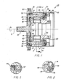
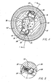
- Clutch 10 which has an axis 11, includes a support housing 12, an outer body 14, which is rotatably mounted on housing 12, and an inner body 16, which is rotatably mounted on outer body 14. Housing 12, outer body 14 and inner body 16 are coaxial along axis 11. Clutch 10 also includes a pair of diametrically opposite rollers 18, 20, which bear against compression member or large pin 22. A torque in direction 24 is applied by inner body 16 on outer body 14 due to the wedging action of rollers 18, 20. Radial forces 26, 27 are applied to compression member 22 by respective rollers 18, 20. Forces 26, 27 are approximately equal and opposite to each other.
- rollers 18, 20 are urged by respective pins 28, 30 with respective springs 32, 34, into a wedging position.
- compression member 22 has a center portion 36, and enlarged end portions 38, 40.
- End portions 38, 40 have respective sleeve bearings 42, 44 and have respective flat end bearing surfaces 43, 45.
- Sleeve bearings 42, 44 are received in respective drilled holes 39, 41 in inner body 16.
- End portions 38, 40 also have abutment portions 35, 37, which contain respective pins 28, 30 and respective springs 32, 34.
- housing 12 has a circular wall section 46 and a left end wall section 48. Sections 46, 48 are joined by peripherally spaced bolts 50. Housing 12 also has a bearing assembly 52, on the left side in Figure 1; and has a bearing assembly 54 on the right side. Bearing 52 is supported by a spacer 49 which is urged axially inwardly by spring 53. Bearing 54 is supported by a spacer 51 which is also urged axially inwardly by its spring 55, for positioning outer body 14. Spacers 49, 51 are free to slide in wall section 46.
- outer body 14 which is driven by inner body 16, has a first shaft 56, which is disposed along axis 11.
- Outer body 14 also has an end wall 60 and a peripheral wall 62 with a radially inner bearing surface 64.
- Outer body 14 also has a left bearing assembly 66 and a right bearing assembly 68.
- Bearing 66 is urged axially inwardly by spring 70.
- Bearing 68 is urged axially inwardly by spring 72.
- Spring 72 is held in position by ring member 74, which is connected to outer body 14 by bolts 76.
- Inner body 16 in Figure 1 has an annular wall portion 78, and has a second shaft portion 80.
- shaft portion 89 drives shaft portion 56.
- inner body 16 transmits torque in torque direction 24 to outer body 14, as inner body 16 is rotated in direction 24.
- Each flat surface 43, 45 coacts with an adjacent portion of radially inner surface 64, forming a slot with a trapezoidal section for receiving a respective roller 18, 20.
- Each roller 18, 20 transmits a shear force from inner body 16 to outer body 14, thereby causing a torque in direction 24 on outer body 14.
- inner body 16 will disengage from torque transmission, if outer body 14 rotates faster than inner body 16.
- Respective abutments 35, 37 limit respective rollers 18, 20 in their travel, when outer body 14 rotates faster than inner body 16.
- Pins 28, 30 with respective springs 32, 34 help to keep rollers 18, 20 in contact with radially inner surface 64 of outer body 14. If outer body 14 rotates slower than inner body 16, pins 28, 30 urge roller 18, 20 into a wedging position. When the radial forces on rollers 18, 20 are great enough to produce a frictional torque on radially inner surface 64 which is greater than its opposing torque, outer body 14 will rotate with inner body 16.
- a pair of pins per roller, with respective springs, can also be used, in place of one pin per roller.
- the radial forces 26, 27 exerted by respective rollers 18, 20 pass through center portion 36 and are equal and opposite forces.
- the forces, which rollers 18, 20 exert on radially inner surface 64 and which correspond to forces 26, 27, are equal forces.
- the rollers 18, 20 are subject to equal contact loads and stresses.
- Compression member 22 moves slightly in a radial direction in order to equalize forces thereon.
- Sleeve bearings 42, 44 which are made of a low friction material, reduce the friction between compression member 22 and inner body 16.
- compression member 22 and its end rollers 18, 20 coact to avoid any side load and to prevent unequal radial forces.
- Radial forces 26, 27 pass through compression member and balance each other, whereby rollers 18, 20 also transmit equal shear forces and equal torques from inner body 16 to outer body 14.
- a relatively small side load is transmitted by friction from compression member 22 to inner body 16. This friction force is minimized by anti-friction bearings 42, 44.
- additional compression members which have diametrically opposite roller members, can be provided.
- Such compression members can be axially spaced along axis 11 from compression member 22.
Landscapes
- Engineering & Computer Science (AREA)
- General Engineering & Computer Science (AREA)
- Mechanical Engineering (AREA)
- Mechanical Operated Clutches (AREA)
- Rolling Contact Bearings (AREA)
Applications Claiming Priority (2)
| Application Number | Priority Date | Filing Date | Title |
|---|---|---|---|
| US261547 | 1988-10-24 | ||
| US07/261,547 US4887703A (en) | 1988-10-24 | 1988-10-24 | Overriding clutch |
Publications (1)
| Publication Number | Publication Date |
|---|---|
| EP0366007A1 true EP0366007A1 (de) | 1990-05-02 |
Family
ID=22993817
Family Applications (1)
| Application Number | Title | Priority Date | Filing Date |
|---|---|---|---|
| EP89119452A Withdrawn EP0366007A1 (de) | 1988-10-24 | 1989-10-20 | Freilaufkupplung |
Country Status (3)
| Country | Link |
|---|---|
| US (1) | US4887703A (de) |
| EP (1) | EP0366007A1 (de) |
| JP (1) | JPH02245525A (de) |
Families Citing this family (4)
| Publication number | Priority date | Publication date | Assignee | Title |
|---|---|---|---|---|
| RU2163313C2 (ru) * | 1999-05-12 | 2001-02-20 | Хамин Иван Никифорович | Порошковая сцепная муфта |
| US8613350B2 (en) | 2009-12-31 | 2013-12-24 | Hiram Lee Nease, III | Infinitely variable wrench |
| US10428801B2 (en) | 2013-03-12 | 2019-10-01 | Jtekt Corporation | Wind power generation device |
| JP6237116B2 (ja) * | 2013-10-28 | 2017-11-29 | 株式会社ジェイテクト | 継手構造及び風力発電装置 |
Citations (3)
| Publication number | Priority date | Publication date | Assignee | Title |
|---|---|---|---|---|
| CH240272A (fr) * | 1942-07-10 | 1945-12-15 | Gavage Armand | Mécanisme d'embrayage. |
| US3034364A (en) * | 1960-03-02 | 1962-05-15 | Littell Machine Co F J | Mechanical lock-up means for overriding drives |
| US3064777A (en) * | 1960-09-06 | 1962-11-20 | Borg Warner | One-way clutch |
Family Cites Families (5)
| Publication number | Priority date | Publication date | Assignee | Title |
|---|---|---|---|---|
| DE277125C (de) * | ||||
| US1936640A (en) * | 1931-08-14 | 1933-11-28 | Blackhawk Mfg Company | Reversible friction clutch |
| US2373812A (en) * | 1944-02-14 | 1945-04-17 | William L Coop | Torque thumbscrew |
| US3369638A (en) * | 1966-03-21 | 1968-02-20 | Boeing Co | Clutch mechanism for dual-input, single-output control system |
| SE333847B (de) * | 1966-11-10 | 1971-03-29 | Scan Coin Ab |
-
1988
- 1988-10-24 US US07/261,547 patent/US4887703A/en not_active Expired - Fee Related
-
1989
- 1989-10-20 EP EP89119452A patent/EP0366007A1/de not_active Withdrawn
- 1989-10-24 JP JP1275094A patent/JPH02245525A/ja active Pending
Patent Citations (3)
| Publication number | Priority date | Publication date | Assignee | Title |
|---|---|---|---|---|
| CH240272A (fr) * | 1942-07-10 | 1945-12-15 | Gavage Armand | Mécanisme d'embrayage. |
| US3034364A (en) * | 1960-03-02 | 1962-05-15 | Littell Machine Co F J | Mechanical lock-up means for overriding drives |
| US3064777A (en) * | 1960-09-06 | 1962-11-20 | Borg Warner | One-way clutch |
Also Published As
| Publication number | Publication date |
|---|---|
| JPH02245525A (ja) | 1990-10-01 |
| US4887703A (en) | 1989-12-19 |
Similar Documents
| Publication | Publication Date | Title |
|---|---|---|
| EP0525126B1 (de) | Einwegantriebsvorrichtung | |
| US5385514A (en) | High ratio planetary transmission | |
| EP0087547A1 (de) | Stufenlos Planetengetriebe mit umlaufenden Doppelkegelrollen | |
| EP2904286B1 (de) | Auffangkupplung mit drehmomentübertragung zwischen radialen oberflächen einer aussenhülse | |
| EP2615323A1 (de) | Elektrischer aktuator mit direktantrieb und elektrische bremsvorrichtung | |
| KR20010112650A (ko) | 평면 래칫 단방향 클러치 | |
| US4887703A (en) | Overriding clutch | |
| EP0038819B1 (de) | Stufenlos verstellbares reibungsgetriebe | |
| JP3010070B2 (ja) | 無段変速機 | |
| US4428246A (en) | Infinitely variable traction roller transmission | |
| US11067154B2 (en) | Toroidal continuously variable transmission | |
| US4463620A (en) | Infinitely variable traction roller transmission | |
| JPH0617712B2 (ja) | 歯車保持装置および該装置を用いた歯車伝導装置 | |
| US4620455A (en) | Traction roller transmission | |
| US4487090A (en) | Friction drive transmission | |
| JPH07113398B2 (ja) | 牽引ロ−ラ無段変速機 | |
| GB2275745A (en) | Torque overload limiter | |
| CA1149642A (en) | Torque transmitting body for traction drive transmissions and normal friction force developing method | |
| RU3797U1 (ru) | Муфта роликовая необратимая | |
| CA1137335A (en) | Traction body construction for infinitely variable transmissions | |
| US4454782A (en) | Torque transmitting body for traction drive transmissions and normal friction force developing method | |
| SU1200027A1 (ru) | Механизм свободного хода | |
| CN117722452A (zh) | 一种自润滑双向逆止器 | |
| JP2003172373A (ja) | 圧延機の駆動用自在継手 | |
| JPS62215160A (ja) | 牽引ロ−ラ変速機 |
Legal Events
| Date | Code | Title | Description |
|---|---|---|---|
| PUAI | Public reference made under article 153(3) epc to a published international application that has entered the european phase |
Free format text: ORIGINAL CODE: 0009012 |
|
| AK | Designated contracting states |
Kind code of ref document: A1 Designated state(s): DE ES FR GB IT NL |
|
| 17P | Request for examination filed |
Effective date: 19901016 |
|
| 17Q | First examination report despatched |
Effective date: 19911031 |
|
| STAA | Information on the status of an ep patent application or granted ep patent |
Free format text: STATUS: THE APPLICATION HAS BEEN WITHDRAWN |
|
| 18W | Application withdrawn |
Withdrawal date: 19920207 |