EP0366023A1 - Manchon à billes pour palier linéaire - Google Patents
Manchon à billes pour palier linéaire Download PDFInfo
- Publication number
- EP0366023A1 EP0366023A1 EP89119538A EP89119538A EP0366023A1 EP 0366023 A1 EP0366023 A1 EP 0366023A1 EP 89119538 A EP89119538 A EP 89119538A EP 89119538 A EP89119538 A EP 89119538A EP 0366023 A1 EP0366023 A1 EP 0366023A1
- Authority
- EP
- European Patent Office
- Prior art keywords
- straight
- cage
- level
- balls
- row
- Prior art date
- Legal status (The legal status is an assumption and is not a legal conclusion. Google has not performed a legal analysis and makes no representation as to the accuracy of the status listed.)
- Granted
Links
Images







Classifications
-
- F—MECHANICAL ENGINEERING; LIGHTING; HEATING; WEAPONS; BLASTING
- F16—ENGINEERING ELEMENTS AND UNITS; GENERAL MEASURES FOR PRODUCING AND MAINTAINING EFFECTIVE FUNCTIONING OF MACHINES OR INSTALLATIONS; THERMAL INSULATION IN GENERAL
- F16C—SHAFTS; FLEXIBLE SHAFTS; ELEMENTS OR CRANKSHAFT MECHANISMS; ROTARY BODIES OTHER THAN GEARING ELEMENTS; BEARINGS
- F16C29/00—Bearings for parts moving only linearly
- F16C29/04—Ball or roller bearings
- F16C29/06—Ball or roller bearings in which the rolling bodies circulate partly without carrying load
- F16C29/0676—Ball or roller bearings in which the rolling bodies circulate partly without carrying load with a bearing body or carriage almost fully embracing the guide rail or track, e.g. a circular sleeve with a longitudinal slot for the support posts of the rail
-
- F—MECHANICAL ENGINEERING; LIGHTING; HEATING; WEAPONS; BLASTING
- F16—ENGINEERING ELEMENTS AND UNITS; GENERAL MEASURES FOR PRODUCING AND MAINTAINING EFFECTIVE FUNCTIONING OF MACHINES OR INSTALLATIONS; THERMAL INSULATION IN GENERAL
- F16C—SHAFTS; FLEXIBLE SHAFTS; ELEMENTS OR CRANKSHAFT MECHANISMS; ROTARY BODIES OTHER THAN GEARING ELEMENTS; BEARINGS
- F16C29/00—Bearings for parts moving only linearly
- F16C29/001—Bearings for parts moving only linearly adjustable for alignment or positioning
-
- F—MECHANICAL ENGINEERING; LIGHTING; HEATING; WEAPONS; BLASTING
- F16—ENGINEERING ELEMENTS AND UNITS; GENERAL MEASURES FOR PRODUCING AND MAINTAINING EFFECTIVE FUNCTIONING OF MACHINES OR INSTALLATIONS; THERMAL INSULATION IN GENERAL
- F16C—SHAFTS; FLEXIBLE SHAFTS; ELEMENTS OR CRANKSHAFT MECHANISMS; ROTARY BODIES OTHER THAN GEARING ELEMENTS; BEARINGS
- F16C29/00—Bearings for parts moving only linearly
- F16C29/04—Ball or roller bearings
- F16C29/06—Ball or roller bearings in which the rolling bodies circulate partly without carrying load
- F16C29/0602—Details of the bearing body or carriage or parts thereof, e.g. methods for manufacturing or assembly
- F16C29/0604—Details of the bearing body or carriage or parts thereof, e.g. methods for manufacturing or assembly of the load bearing section
-
- F—MECHANICAL ENGINEERING; LIGHTING; HEATING; WEAPONS; BLASTING
- F16—ENGINEERING ELEMENTS AND UNITS; GENERAL MEASURES FOR PRODUCING AND MAINTAINING EFFECTIVE FUNCTIONING OF MACHINES OR INSTALLATIONS; THERMAL INSULATION IN GENERAL
- F16C—SHAFTS; FLEXIBLE SHAFTS; ELEMENTS OR CRANKSHAFT MECHANISMS; ROTARY BODIES OTHER THAN GEARING ELEMENTS; BEARINGS
- F16C29/00—Bearings for parts moving only linearly
- F16C29/04—Ball or roller bearings
- F16C29/06—Ball or roller bearings in which the rolling bodies circulate partly without carrying load
- F16C29/068—Ball or roller bearings in which the rolling bodies circulate partly without carrying load with the bearing body fully encircling the guide rail or track
- F16C29/0683—Ball or roller bearings in which the rolling bodies circulate partly without carrying load with the bearing body fully encircling the guide rail or track the bearing body encircles a rail or rod of circular cross-section, i.e. the linear bearing is not suited to transmit torque
- F16C29/0685—Ball or roller bearings in which the rolling bodies circulate partly without carrying load with the bearing body fully encircling the guide rail or track the bearing body encircles a rail or rod of circular cross-section, i.e. the linear bearing is not suited to transmit torque with balls
- F16C29/069—Ball or roller bearings in which the rolling bodies circulate partly without carrying load with the bearing body fully encircling the guide rail or track the bearing body encircles a rail or rod of circular cross-section, i.e. the linear bearing is not suited to transmit torque with balls whereby discrete load bearing elements, e.g. discrete load bearing plates or discrete rods, are provided in a retainer and form the load bearing tracks
-
- F—MECHANICAL ENGINEERING; LIGHTING; HEATING; WEAPONS; BLASTING
- F16—ENGINEERING ELEMENTS AND UNITS; GENERAL MEASURES FOR PRODUCING AND MAINTAINING EFFECTIVE FUNCTIONING OF MACHINES OR INSTALLATIONS; THERMAL INSULATION IN GENERAL
- F16C—SHAFTS; FLEXIBLE SHAFTS; ELEMENTS OR CRANKSHAFT MECHANISMS; ROTARY BODIES OTHER THAN GEARING ELEMENTS; BEARINGS
- F16C29/00—Bearings for parts moving only linearly
- F16C29/08—Arrangements for covering or protecting the ways
- F16C29/084—Arrangements for covering or protecting the ways fixed to the carriage or bearing body movable along the guide rail or track
- F16C29/088—Seals extending in the longitudinal direction of the carriage or bearing body
-
- F—MECHANICAL ENGINEERING; LIGHTING; HEATING; WEAPONS; BLASTING
- F16—ENGINEERING ELEMENTS AND UNITS; GENERAL MEASURES FOR PRODUCING AND MAINTAINING EFFECTIVE FUNCTIONING OF MACHINES OR INSTALLATIONS; THERMAL INSULATION IN GENERAL
- F16C—SHAFTS; FLEXIBLE SHAFTS; ELEMENTS OR CRANKSHAFT MECHANISMS; ROTARY BODIES OTHER THAN GEARING ELEMENTS; BEARINGS
- F16C43/00—Assembling bearings
- F16C43/04—Assembling rolling-contact bearings
- F16C43/06—Placing rolling bodies in cages or bearings
Definitions
- the invention relates to a linear ball bushing comprising a cage with a cage axis and with a plurality of ball revolutions, wherein each ball circulation has two rows of straight balls substantially parallel to the cage axis, namely a row of supporting balls and a row of return balls and two rows of arcs connecting the two rows of straight balls, wherein each of the ball revolutions bears radially outwards on a running plate which is inserted into an associated recess of the cage and has an outer surface for abutment against an inner peripheral surface of a bearing housing bore which receives the cage, a closed raceway for the respective ball circulation is further formed on an inner surface of the running plate, the closed track also has two straight track sections, namely a load-bearing straight track section for the supporting ball row and a returning straight track section for the return ball row and two curved track sections connecting the straight track sections, wherein the load-bearing straight track section, based on the outer surface of the running plate, is at a higher level and the returning straight track section,
- the running plate is designed as an annular shell, the straight track sections extending in their extension towards a shell border.
- the basic geometry creates the prerequisites for a continuous ball guide that extends over the entire ball run, which could ensure a smooth running of the balls.
- it is Machining the straight track sections - and in particular the load-bearing straight track section requires careful processing - difficult because the straight track sections meet with their imaginary extensions against the edge of the shell.
- the invention is based on the object of specifying a design of the running plate in a linear ball bushing of the type described at the outset, which facilitates the machining of the straight track sections and in particular the load-bearing straight track section while maintaining the most complete possible ball guidance over the entire ball circulation.
- the central rib is continued essentially constant in profile up to the ends of the running plate and traversed by the arc track sections, and that extensions of the two straight running track sections are continued essentially constant in profile up to the ends of the running plate, intersecting with the Arc raceway sections.
- the straight running track sections which continue essentially to a constant profile up to the ends of the running board and here in particular the supporting straight running track section again.
- the parallelism of the two straight track sections makes it possible, if necessary, to grind both straight track sections together with a single grinding tool. Because the central rib is traversed by the arc track sections, the guidance of the balls is retained on most of the ball circulation, at least in the apex of the ball circulation.
- a running plate for linear ball bushings of a generic type is known, on the inner surface of which the two straight track sections are formed separated from one another by a central rib.
- the central rib ends at a distance from the ends of the running plate.
- plane surfaces are formed which are parallel to the plane defined by the ball center points of the ball circulation. This eliminates any lateral guidance of the balls in the area of the arc track sections. This is highlighted in DE-OS 35 12 013 as the inventive feature, on the grounds that the need for a precise, mutual adjustment of lateral guidance in the cage and lateral guidance in the running plate in the region of the respective arc track section is avoided.
- the running plates can in principle be milled from the full by a relatively simple, mechanical processing, thanks to the constant profile.
- a particularly simple possibility for the provision of the running plate blanks is again due to the constant profile in the form of the extrusion of a metal blank or a powder-metallurgical pile.
- the sheet track sections can be formed by embossing.
- the level drop in the career starts from the level of the supporting straight track section in the direction of the level of the returning straight track section in each case in the region of linear end extensions of the supporting straight track section.
- the level drop existing in the area of a linear final extension of the supporting straight track section can of course also be obtained by the embossing processing which is used to form the curved track section. This measure also achieves a particularly gentle use of the drop in level, which is important for smooth running.
- the track it is also possible for the track to pass through a minimum level in the transition region between the arc sections of the sheet track sections and the return straight line of the returning straight track section.
- This measure ensures that a certain lateral guidance of the balls is also ensured in the partial arc area of a sheet track section which extends from the apex to the returning straight track section, in particular if, according to a further development, the track is in the area rectilinear end extensions of the returning straight track section gradually increases from the respective level minimum to the level of the returning straight track section.
- the straight track sections and / or curved track sections have a groove cross section whose radius of curvature is approximately the same, preferably slightly larger, than the ball radius.
- the running plates rock against the inner circumferential surface of the bearing housing bore receiving the cage, namely about a swing axis which is approximately tangential to the cage axis in a plane perpendicular to the cage axis, and preferably in the area of the longitudinal center of the ball bushing.
- a swing axis which is approximately tangential to the cage axis in a plane perpendicular to the cage axis, and preferably in the area of the longitudinal center of the ball bushing.
- the rocking ability could also be derived from the elastic deformability of the cage material.
- the rocking system on the inner circumferential surface of the bearing housing bore can be realized in a very simple manner in that the outer surface of the running plate drops radially inwards with respect to the cage axis from a central region located in the area of the swing axis to the ends of the running plate.
- the profile bar can be provided using one of the methods described above.
- At least one of the straight grooves can be ground after the arch grooves have been impressed, it being understood from the above that in particular the arch groove which results in the load-bearing track section, that is to say the higher-level straight groove, is ground.
- the embossing depth of the sheet grooves in the connection areas to the lower-level straight groove be selected such that level there minima arise and are possibly still present even after grinding the lower-level straight groove.
- recesses be provided at the ends of the profiled rod, which recesses receive at least part of the displaced running plate material during embossing.
- Embossing tools can be used, which are adapted to the shape of the profile bar, also with regard to the recess, in such a way that the shape is completely filled after the embossing, so that defined edges and surfaces also result in the region of the recess.
- the outer surface can be sanded before or after grinding the straight grooves, if necessary in such a way that the rockability occurs. It is particularly recommended that the outer surface be ground after the straight grooves have been ground, the ground straight grooves being used to position the profile bar when grinding the outer surface.
- the invention further relates to a linear ball bushing comprising a cage with a cage axis and with a plurality of ball revolutions, wherein each ball circulation has two rows of straight balls substantially parallel to the cage axis, namely a row of supporting balls and a row of return balls and two rows of arcs connecting the two rows of straight balls, wherein at least the row of supporting balls of a ball recirculation bears radially outwards on a running plate which is inserted into an associated recess in the cage and has an outer surface for bearing against an inner peripheral surface of a bearing housing bore which receives the cage, wherein, on an inner surface of the running plate, a straight track section is formed at least for the supporting ball row of the respective ball circulation, and wherein the respective supporting ball row penetrates radially inward a slot of the cage in order to be able to bear against a shaft enclosed by the cage.
- the running plates have a crest-shaped tilting bearing on the outside in their longitudinal center or are continuously spherical on their outside along their entire length
- the running plate have a central area on its outer surface, which is parallel runs to the track of the row of supporting balls and that axially outer longitudinal areas adjoin this central longitudinal area via radially convex roundings, which preferably extend in a straight line axially outward and radially inward.
- the total axial length of a row of support balls is approx. 100% to approx. 200%, preferably approx. 130% to approx. 180% of the associated shaft diameter, that the axial length of the central longitudinal region is approximately 2% to approximately 15% of the associated shaft diameter, preferably approximately 5% to approximately 10% of the associated shaft diameter, that the rounding has a radius of curvature which is more than 100%, preferably more than 150%, for example 167% to 300% of the associated shaft diameter and that the inclination of the axially outer longitudinal regions with respect to the raceway of the row of supporting balls is on average approximately 25 to approximately 45 angular minutes, preferably approximately 35 angular minutes.
- the running plates are mounted on their outer surface by embossing a surrounding jacket.
- This surrounding jacket leads to an undesirable enlargement of the outside diameter, which can only be compensated for by thin running plates or small balls.
- a surrounding jacket is not required.
- the linear ball bushing can be inserted into the bearing housing bore in such a way that the running plates lie directly against the inner circumferential surface.
- a linear ball bushing is generally designated 10. It comprises a cage 12 made of hard elastic plastic. In this cage 12 running plates 14 are inserted, each having an outer peripheral surface 16 for abutment against a linear housing 10 receiving the bearing housing bore and an inner peripheral surface 18.
- the running plates 14 consist of a hard material, in particular hardened steel.
- the balls are labeled 20.
- Each ball circulation forms a support ball row 22 and a return ball row 24.
- the support ball rows 22 protrude through slots 26 of the cage 12 radially inwards to bear against a shaft, not shown.
- the return ball rows 24 are supported radially inward by the cage 12.
- Both rows of straight balls 22 and 24 rest on the inner circumferential surface 18 of the respective running plate 14.
- the support ball row 22 and the return ball row 24 are each connected by curved ball rows 28.
- the running plates 14 are held positively in the cage 12, but with a certain amount of play.
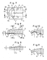
- a running plate 14 is shown in detail in FIGS. 3, 4 and 5.
- This running plate 14 is produced on the basis of a profile bar, the profile of which can be seen from FIG.
- the running plate 14 has a load-bearing straight track section 30 which has a first higher level compared to the outer peripheral surface 16 and a returning straight track section 32 which has a lower level compared to the outer peripheral surface 16.
- the load-bearing track section 30 serves to receive the support ball row 22 and the straight track section 32 for receiving the return ball row 24.
- the two straight track sections 30 and 32 are connected to one another by curved track sections 36.
- the straight raceway sections 30 and 32 extend with the end sections 30a and 32a in a substantially constant profile to the ends of the running plate 14.
- the running plate 14 has a constant profile and is through the arc track sections 36 only interrupted.
- the raceway plate On its outer circumferential surface 16, the raceway plate is curved, as shown in FIG. 6, so that it swings against the inner circumferential surface of a bearing housing bore.
- the straight track sections 30 and 32 are rounded with a radius of curvature which is equal to or slightly larger than the radius of the balls 20.
- bores 40 and 42 at the ends of the running plate.
- the bores 40 are intended for receiving cup-shaped end rings 44 (FIG. 1) which secure the running plate 14 and end plates 46 on the cage 12.
- the recesses 42 are intended to receive circlips for axially securing the ball bushing in a receiving bore.
- the arc raceway sections 36 extend over approximately 180 ° and are approximately circularly curved.
- the drop in level from the straight track section 30 to the straight track section 32 already begins in an end section a of the straight track section 30.
- the sole of the curved track section 36 lies in the area of the intersection with the straight track section 30 lower than an imaginary continuation of the sole of the straight track section 30, and a lateral guidance of the Balls are also guaranteed in this intersection area.
- the level drop in the end section a is represented by the angle 2 ° in FIG. 8.
- the level drop in the immediately adjacent area of the arch Raceway section 36 is, as also shown in Figure 8, about 5 °. There are no level jumps.
- the gradients are rounded.
- the longitudinal extent of the end section a is so large even after grinding that the loaded balls can be continuously relieved before entering the sheet track section 36. This also applies analogously to the balls entering the load zone. This measure ensures a smooth and jerk-free process.
- the sheet track 36 has a level minimum which is below the level of the returning straight track 32. A slow rise in level takes place in the end section b of the returning straight track section 32. There are no level jumps.
- the gradients are rounded. The level minimum 6 is still present even after grinding the returning straight track section 32.
- the downward gradients a and b of the straight track sections 30, 32 are embossed together with the curved track sections 36.
- the tapering of the rib width of the central rib 38 in the region of the end sections a and b results in a funnel-shaped transition from the curved track section 36 into the straight track sections 30 and 32.
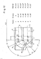
- 1 tolib denote various measuring points, some of which have also been entered in FIG. 7, in order to make the relationships between FIGS. 7 and 12 clear.
- these measuring points are assigned various level values for the sake of example.
- the level values denote the relative level height in millimeters in each case on the sole of the track compared to the level of the base of the load-bearing track section 30, which is rated zero.
- FIG. 12 also conveys an order of magnitude of the length of the ball bushing.
- the outer diameter of the cage 12 is 40 mm in the example, that a total of 10 running plates are provided, as shown in FIG. 2, that the peripheral extension of a running plate is 9.7 mm, and that the ball diameter is 3.969 mm.
- the radius of curvature of the raceway measured on the sole is 2.04 mm.
- the respective radii of the track sections are recorded in millimeters. It can be seen that these radii are slightly larger than the radius of the sphere, so that the balls are guided laterally. It can be seen from FIG. 12 and the table that lateral guidance is guaranteed in the area 1 to 4; this side guide is supplemented in the apex region 4 by the extension 38a of the rib 38. Even in the relatively uncritical range 4 to 7 a certain lateral guidance of the balls through the running plate is still guaranteed, as indicated by the intersection line 50. It should be mentioned again that the individual downhill sections from 1 to 7 essentially merge into one another.
- the guidance of the balls is supplemented by the cage 12.
- the guide surfaces in the cage 12 are manufactured with high precision so that they are attached to the Connect the guide surfaces of the running plates without offset.
- the recesses 52 which can be seen in FIGS. 3 and 7 serve in part to absorb the material when embossing the 80 gene track sections 36; in other words: during stamping, the running plates 14 are inserted with previously formed recesses in stamping molds which lie against the outer circumferential surface 16 and the end surfaces, but leave so much air in the region of the recesses 52 that the material displaced during the stamping can flow in and the geometry of the Cutouts according to FIG. 7 arise.
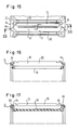
- FIG. 13 shows the cage according to FIG. 2 after removal of the running plates 14 and the balls 20.
- the recesses 60 for receiving the running plates 14 of FIG. 2 can be seen there.
- the slots 26 which allow the balls of the supporting ball row (22) to partially pass through can also be seen, and the running track 62 for the return ball row 24 of FIG. 2 can be seen. All of this is also shown in an enlarged view in FIG. 14. It can also be seen from FIGS. 14 and 15 that at the ends of the recesses 60, specifically adjacent to the end faces 64 of the recesses 60, groove-shaped filling slopes 66 are arranged in alignment with the raceways 62, the meaning of which can be seen in particular from FIG. 19.
- a filling tube 68 is attached there for filling the balls 20 of a ball circulation, so that it is approximately in continuation of the respective filling slope 66.
- the upper cup-shaped end ring 44 is removed, while the lower cup-shaped end ring 44 assumes its securing position with respect to the running plates 14. Since the upper end ring 44 is missing, the running plate 14 can be tilted, as can be seen from FIG. It is possible to incline the running plates 14 because the longitudinal boundary surfaces 70, 72 of the recess 60 are approximately parallel to one another, or else the plastic material of the cage 12 is so elastic that the running plate 14 can be forced out.
- the type of filling using the filling slope 66 and the chamfer 74 is not restricted to the fact that the two straight track sections 30, 32 and the arc track sections are provided on the running plate 14 36 are attached. Rather, the type of filling would also be conceivable if the running plates 14 were restricted to the width of the straight track sections 30 of the rows of supporting balls. In this case, only the filler bevels 66 and the bevels 74 would have to be installed in alignment with the respective straight track section 30 of a supporting row of balls.
- a linear ball bearing can be seen in FIG. 20, in which the shaft 178 is supported by stands 180 and the cage 112 is designed in the form of a partial ring.
- the cage is again provided at its ends with end rings 144, which are partially ring-shaped in accordance with the circumferential extent of the cage 112. Seals are provided to prevent dirt from entering the area of the balls.
- a ring recess 184 which is defined by an axially directed surface 184a and a radially inwardly directed surface 184b.
- the base body 146a lies with axial play between the axially directed surface 184a of the cage 112 and an axially directed surface 144a of the end ring 144.
- the excess of the recess 184 compared to the diameter of the base body 146a allows the base body 146a radial play within the recess 184. This radial play also exists in the embodiment according to FIG. 1, is also of essential importance there, but has not been mentioned there until now been.
- the radial play is necessary to enable the sealing ring 146 to be adapted to the changed geometry when the shaft 178 is angularly adjusted relative to the cage 112. While in the embodiment according to FIGS. 1 to 13 the sealing ring 46 (referred to there as the cover plate) is closed in a circle and may therefore be movable in the peripheral direction without this interfering with the storage operation, according to the invention the sealing rings 146 are partially ring-shaped, ie open. There is still a need to allow the sealing rings 146 radial play to allow them to adapt to changed bearing geometry in the event of loss of escape between shaft 178 and cage 112.
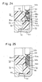
- FIGS. 23 and 24 In order to make the sealing ring 146 movable in the radial direction, but to fix it in the peripheral direction, a design is provided as shown in detail in FIGS. 23 and 24.
- Cams 188 which can also be seen in FIGS. 22 and 23, rise above the axially directed surface 184a. These cams 188 penetrate openings 190, as can be seen from FIGS. 23 and 24.
- the openings 190 have a radial oversize compared to the radial width of the cams 188, so that the sealing rings 146 still have a radial play.
- the cams 188 are only attached in the end regions of the sealing ring 146, that is to say close to the support bearings 180 in FIG.
- the height of the cams 188 compared to the axially directed surface 184a of the cage 112 is greater than the axial thickness of the respective base body 146a.
- the surface 144a that is to say the inside of the pot base 144b of the cup-shaped end ring 144, lies against the end surface 188a of the respective cam 188 and is screwed to the cage there. The screwing takes place by means of a countersunk screw 192, which is screwed into the cam 188.
- longitudinal sealing strips 194 with a root part 194a and a tongue part 194b abutting the shaft 178 are also provided in the area of the gap delimitation surfaces 186 in the cage 112.
- the root part 194a is inserted in an axially extending and radially inwardly open groove 196 of the cage 112 near its respective gap-limiting surface 186.
- the grooves 196 each extend up to the axially directed surfaces 184a and are expanded peripherally in their end sections e, so that support shoulders 198 are formed (FIG. 26).
- the root parts 194a of the longitudinal sealing strips 194 have, in the axial end regions, peripherally projecting projections 200 which bear against the support shoulders 198.
- the longitudinal sealing strips 194 have extensions 202, which project beyond the projections 200 axially in the direction of the bottom wall 144b of the end ring 144, so that, as shown in FIG. 23, the sealing ring 146 comes into contact with the extension 202. Due to the mutual abutment of the extensions 202 and the sealing rings 146 in the area of the gap 184-186, the intermediate space between the shaft 178 and the cage 112 is completely sealed.
- FIG. 27 shows the longitudinal sealing strip 194 before assembly. Axially outside of the projections 200, grip elements 204 are attached to the two ends of a longitudinal sealing strip 194, which, when the longitudinal sealing strips 194 are assembled, allow the sections between the projections 200 to be stretched such that the projections 200 are pushed over the shoulder surfaces 198 and onto them can be stored. After assembly, the handle elements 204 are separated outside the extensions 202, leaving the extensions 202.
- FIG. 28 shows a running plate 14, the outer surface 16 of which has already been indicated schematically in FIG. 6.
- the outer surface 16 has a central rectilinear longitudinal section f, to which an axial longitudinal section h, which is also rectilinear, is connected via transition curves g with a radius of curvature gl.
- the longitudinal section h forms an angle ⁇ of 35 angular minutes with the longitudinal section f.
- the total length of the supporting row of balls is designated i. The following applies to the size ratios:
- the length i of the row of supporting balls is approximately 100% to approximately 200%, preferably approximately 130% to approximately 180% of the diameter of the shaft 178; the length of the central longitudinal section f is approximately 2% to approximately 15%, preferably approximately 5% to approximately 10% of the diameter of the shaft 178; the radius of curvature gl of the transition rounding g is more than approx. 100%, preferably more than approx. 150% and for example 167% to 300% of the diameter of the shaft 178.
- the angle inclination ⁇ is approx. 25 to 45 angular minutes, in the example case approx. 35 Angular minutes.
- the running plates 14 still have a certain ability to tilt or rock, but on the other hand, in normal operation, due to the straightness in the central longitudinal region f, the surface pressure is reduced to such an extent that the wear remains small compared to a surrounding bearing bore . It has also been shown that if the dimensions specified in the range of the tilting movements to be expected in the event of loss of escape between the shaft axis and the cage axis are maintained, the approach of diametrically opposed running plates 14 remains within acceptable limits and thus also the pressure which the balls bear against the shaft 178 on the one hand and exercise against the tread plates 14 on the other hand.
- the embodiment of the running plates according to FIG. 28 can be used in all embodiments of the linear ball bearing as described above and can also be used.
- running plates on their outer surface 16, as shown in FIG. 2 are rounded in accordance with the inner peripheral surface of a receiving bearing housing bore, so that a flat contact of the running plates in the region of the central longitudinal section f with the bearing housing bore is ensured.
Landscapes
- Engineering & Computer Science (AREA)
- General Engineering & Computer Science (AREA)
- Mechanical Engineering (AREA)
- Bearings For Parts Moving Linearly (AREA)
- Grinding And Polishing Of Tertiary Curved Surfaces And Surfaces With Complex Shapes (AREA)
- Forging (AREA)
Priority Applications (1)
| Application Number | Priority Date | Filing Date | Title |
|---|---|---|---|
| AT89119538T ATE94259T1 (de) | 1988-10-21 | 1989-10-20 | Linearkugelbuechse. |
Applications Claiming Priority (4)
| Application Number | Priority Date | Filing Date | Title |
|---|---|---|---|
| DE3835971 | 1988-10-21 | ||
| DE3835971 | 1988-10-21 | ||
| DE3910469 | 1989-03-31 | ||
| DE3910469A DE3910469A1 (de) | 1988-10-21 | 1989-03-31 | Linearkugelbuechse stichwort: linearkugelbuechse mit schaukelnden stahleinlagen |
Publications (2)
| Publication Number | Publication Date |
|---|---|
| EP0366023A1 true EP0366023A1 (fr) | 1990-05-02 |
| EP0366023B1 EP0366023B1 (fr) | 1993-09-08 |
Family
ID=25873488
Family Applications (1)
| Application Number | Title | Priority Date | Filing Date |
|---|---|---|---|
| EP89119538A Expired - Lifetime EP0366023B1 (fr) | 1988-10-21 | 1989-10-20 | Manchon à billes pour palier linéaire |
Country Status (6)
| Country | Link |
|---|---|
| US (1) | US5152614A (fr) |
| EP (1) | EP0366023B1 (fr) |
| JP (1) | JPH07117101B2 (fr) |
| BR (1) | BR8905347A (fr) |
| DE (2) | DE3910469A1 (fr) |
| ES (1) | ES2045338T3 (fr) |
Families Citing this family (18)
| Publication number | Priority date | Publication date | Assignee | Title |
|---|---|---|---|---|
| DE4210039C3 (de) * | 1992-03-27 | 2002-08-08 | Ina Schaeffler Kg | Kugelumlaufeinheit für eine Linearführung |
| DE69217209T2 (de) * | 1992-06-26 | 1997-05-15 | Sgs Thomson Microelectronics | Einschalt-Rücksetzschaltung mit niedrigem Ruhestromverbrauch |
| DE4223499C2 (de) * | 1992-07-17 | 2002-02-21 | Schaeffler Waelzlager Ohg | Wälzlager für eine geradlinige Bewegung |
| DE4318427C2 (de) * | 1993-06-03 | 2001-05-31 | Schaeffler Waelzlager Ohg | Wälzkörperumlauflager |
| US5437220A (en) * | 1994-05-24 | 1995-08-01 | Cheng; Chi | Ball bearing piston |
| US5669716A (en) * | 1995-03-14 | 1997-09-23 | Hiwin Technologies Corporation | Linear ball bearing |
| US5649770A (en) * | 1996-04-04 | 1997-07-22 | Hiwin Technologies Corp. | Ball circulating structure for linear guide assembly |
| DE19615791A1 (de) * | 1996-04-20 | 1997-10-23 | Schaeffler Waelzlager Kg | Linearwälzlager mit Längsdichtungen |
| US5809834A (en) * | 1996-06-14 | 1998-09-22 | Mrba Company | Motion roller bearing assembly |
| DE19811495B4 (de) * | 1998-03-17 | 2010-04-01 | Skf Linearsysteme Gmbh | Lagerbefestigung |
| DE10125381B4 (de) * | 2001-05-23 | 2007-11-22 | Bosch Rexroth Mechatronics Gmbh | Lagerblock mit Stange |
| US20080118193A1 (en) * | 2006-11-21 | 2008-05-22 | Tsung-Jen Chen | Roller Circulating Device for a Linear Guideway |
| DE102007013164A1 (de) * | 2007-03-20 | 2008-09-25 | Schaeffler Kg | Wälzlager mit einer Bremseinrichtung |
| DE102007051229A1 (de) * | 2007-10-26 | 2009-04-30 | Schaeffler Kg | Wälzlager mit einer Bremseinrichtung |
| DE102008053901A1 (de) | 2008-10-30 | 2010-05-06 | Schaeffler Kg | Tragbahnelement für ein Linearkugellager und Herstellverfahren für das Tragbahnelement sowie Linearkugellager |
| DE102008053933A1 (de) | 2008-10-30 | 2010-05-06 | Schaeffler Kg | Linearkugellager und Tragbahnelement dafür sowie Herstellverfahren und Umformvorrichtung für einen Rohling des Tragbahnelementes |
| DE102017205315A1 (de) | 2017-03-29 | 2018-10-04 | Robert Bosch Gmbh | Wälzkörpervorrichtung mit autarker Energieversorgung |
| DE102023202496A1 (de) | 2023-03-21 | 2024-09-26 | Robert Bosch Gesellschaft mit beschränkter Haftung | Ausscheidungsgehärtete Laufbahneinlage für ein Linearwälzlager |
Citations (4)
| Publication number | Priority date | Publication date | Assignee | Title |
|---|---|---|---|---|
| FR2075227A5 (fr) * | 1970-01-27 | 1971-10-08 | Star Kugelhalter Gmbh Dt | |
| FR2335727A1 (fr) * | 1975-12-19 | 1977-07-15 | Skf Ind Trading & Dev | Roulement a billes pour deplacements lineaires |
| DE1949182C3 (de) * | 1969-05-07 | 1985-03-21 | Deutsche Star Kugelhalter Gmbh, 8720 Schweinfurt | Kugellager für längsbewegliche Maschinenteile |
| DE8811178U1 (de) * | 1988-09-03 | 1988-12-08 | SKF Linearsysteme GmbH, 8720 Schweinfurt | Wälzlagervorrichtung für Längsbewegungen |
Family Cites Families (15)
| Publication number | Priority date | Publication date | Assignee | Title |
|---|---|---|---|---|
| DE1287382B (de) * | 1961-07-07 | 1969-01-16 | Opel Adam Ag | Buechse zur Lagerung von hin- und herbeweglichen Maschinenteilen |
| US3560061A (en) * | 1968-07-11 | 1971-02-02 | Howard C Shaw Jr | Means for mounting translating machine member |
| SE371270B (fr) * | 1973-04-24 | 1974-11-11 | Skf Nova Ab | |
| US4206951A (en) * | 1976-04-02 | 1980-06-10 | Skf Kugellagerfabriken Gmbh | Linear rolling bearing |
| DE2626399A1 (de) * | 1976-06-12 | 1977-12-22 | Schaeffler Ohg Industriewerk | Kugellager zur laengsbeweglichen lagerung von wellen |
| US4128278A (en) * | 1977-08-30 | 1978-12-05 | Brown & Sharpe Manufacturing Company | Linear motion ball bearing with dynamic stiffness |
| FR2434955A1 (fr) * | 1978-08-30 | 1980-03-28 | Schaeffler Ohg Industriewerk | Palier a billes pour le montage d'arbres animes d'un mouvement longitudinal |
| JPS59222619A (ja) * | 1983-05-30 | 1984-12-14 | Hiroshi Teramachi | 直線摺動用ベアリングの隙間調整方法 |
| JPS5848771B2 (ja) * | 1981-02-23 | 1983-10-31 | 博 寺町 | リニヤボ−ルベアリング |
| US4417771A (en) * | 1982-06-22 | 1983-11-29 | Hiroshi Teramachi | Linear ball bearing unit |
| DE3326601A1 (de) * | 1983-07-23 | 1985-02-07 | Skf Kugellagerfabriken Gmbh | Kugellager fuer laengsbewegungen |
| US4572591A (en) * | 1983-09-02 | 1986-02-25 | Skf Kugellagerfabriken Gmbh | Ball bearing arrangement for longitudinal movement on a shaft or the like |
| US4512617A (en) * | 1984-03-06 | 1985-04-23 | The Barden Corporation | Linear ball bearing which accommodates shaft misalignment |
| DE3512013A1 (de) * | 1985-04-02 | 1986-10-02 | Skf Linearsysteme Gmbh | Kugellager fuer laengsbewegungen |
| JPS6233140Y2 (fr) * | 1985-10-15 | 1987-08-25 |
-
1989
- 1989-03-31 DE DE3910469A patent/DE3910469A1/de active Granted
- 1989-10-19 JP JP1270486A patent/JPH07117101B2/ja not_active Expired - Lifetime
- 1989-10-20 DE DE89119538T patent/DE58905523D1/de not_active Expired - Fee Related
- 1989-10-20 EP EP89119538A patent/EP0366023B1/fr not_active Expired - Lifetime
- 1989-10-20 BR BR898905347A patent/BR8905347A/pt not_active IP Right Cessation
- 1989-10-20 ES ES89119538T patent/ES2045338T3/es not_active Expired - Lifetime
-
1991
- 1991-03-14 US US07/670,360 patent/US5152614A/en not_active Expired - Lifetime
Patent Citations (4)
| Publication number | Priority date | Publication date | Assignee | Title |
|---|---|---|---|---|
| DE1949182C3 (de) * | 1969-05-07 | 1985-03-21 | Deutsche Star Kugelhalter Gmbh, 8720 Schweinfurt | Kugellager für längsbewegliche Maschinenteile |
| FR2075227A5 (fr) * | 1970-01-27 | 1971-10-08 | Star Kugelhalter Gmbh Dt | |
| FR2335727A1 (fr) * | 1975-12-19 | 1977-07-15 | Skf Ind Trading & Dev | Roulement a billes pour deplacements lineaires |
| DE8811178U1 (de) * | 1988-09-03 | 1988-12-08 | SKF Linearsysteme GmbH, 8720 Schweinfurt | Wälzlagervorrichtung für Längsbewegungen |
Also Published As
| Publication number | Publication date |
|---|---|
| JPH02154810A (ja) | 1990-06-14 |
| EP0366023B1 (fr) | 1993-09-08 |
| BR8905347A (pt) | 1990-05-22 |
| JPH07117101B2 (ja) | 1995-12-18 |
| ES2045338T3 (es) | 1994-01-16 |
| DE3910469C2 (fr) | 1990-09-06 |
| US5152614A (en) | 1992-10-06 |
| DE3910469A1 (de) | 1990-04-26 |
| DE58905523D1 (de) | 1993-10-14 |
Similar Documents
| Publication | Publication Date | Title |
|---|---|---|
| EP0366023B1 (fr) | Manchon à billes pour palier linéaire | |
| DE3303831C2 (fr) | ||
| DE3429480C2 (fr) | ||
| DD302032A7 (de) | Ausbildung einer schmiermittelversorgung bei einem waelzlager fuer linearbewegungen | |
| DE19600031C2 (de) | Vertikal einstellbarer Maschinenträger | |
| DE3832087A1 (de) | Kugelkopfstirnfraeser | |
| DE3036323C2 (de) | Lineare Kugellagereinheit | |
| EP0504951B1 (fr) | Procédé pour le montage d'une bande d'étanchéité longitudinale dans un palier linéaire à billes et bande d'étanchéité longitudinale pour la mise en oeuvre du procédé | |
| WO2007012211A1 (fr) | Guide lineaire | |
| DE3816914A1 (de) | Kreuz-kegelrollenlager | |
| DE3304783A1 (de) | Linearlager-baugruppe | |
| EP2409045A1 (fr) | Palier à rouleaux sphériques, destiné en particulier à recevoir une charge combinée radiale et axiale | |
| EP0390155B1 (fr) | Palier linéaire à billes avec creux de remplissage pour billes | |
| DE2231541A1 (de) | Rollspindel | |
| DE2724849A1 (de) | Mehrreihiges waelzlager | |
| EP0353396A1 (fr) | Palier linéaire | |
| DE3101315C3 (de) | Durch Keilwirkung betätigtes Backenfutter für eine Werkzeugmaschine | |
| DE19830228A1 (de) | Backe für einen Kompressor des Taumelscheibentyps und Backenanordnung | |
| DE3331287A1 (de) | Verfahren zum schleifen eines lagerkoerpers, insbesondere fuer ein linearkugellager, und linearkugellager mit einem erfindungsgemaess geschliffenen lagerkoerper | |
| DE3905566C1 (de) | Gleichlaufgelenk mit axial gegeneinander verschiebbaren Gelenkteilen | |
| DE3117491A1 (de) | "linear-rollenlager" | |
| DE4210039C2 (de) | Kugelumlaufeinheit für eine Linearführung | |
| DE3211096A1 (de) | Kugellager | |
| DE3038377C2 (de) | Rollenumlaufschuh | |
| DE9011413U1 (de) | Linearantrieb |
Legal Events
| Date | Code | Title | Description |
|---|---|---|---|
| PUAI | Public reference made under article 153(3) epc to a published international application that has entered the european phase |
Free format text: ORIGINAL CODE: 0009012 |
|
| AK | Designated contracting states |
Kind code of ref document: A1 Designated state(s): AT BE CH DE ES FR GB IT LI NL SE |
|
| 17P | Request for examination filed |
Effective date: 19900620 |
|
| 17Q | First examination report despatched |
Effective date: 19911220 |
|
| GRAA | (expected) grant |
Free format text: ORIGINAL CODE: 0009210 |
|
| AK | Designated contracting states |
Kind code of ref document: B1 Designated state(s): AT BE CH DE ES FR GB IT LI NL SE |
|
| REF | Corresponds to: |
Ref document number: 94259 Country of ref document: AT Date of ref document: 19930915 Kind code of ref document: T |
|
| GBT | Gb: translation of ep patent filed (gb section 77(6)(a)/1977) |
Effective date: 19930902 |
|
| ITF | It: translation for a ep patent filed | ||
| REF | Corresponds to: |
Ref document number: 58905523 Country of ref document: DE Date of ref document: 19931014 |
|
| ET | Fr: translation filed | ||
| REG | Reference to a national code |
Ref country code: ES Ref legal event code: FG2A Ref document number: 2045338 Country of ref document: ES Kind code of ref document: T3 |
|
| PLBI | Opposition filed |
Free format text: ORIGINAL CODE: 0009260 |
|
| 26 | Opposition filed |
Opponent name: SKF GMBH Effective date: 19940603 |
|
| NLR1 | Nl: opposition has been filed with the epo |
Opponent name: SKF GMBH. |
|
| EAL | Se: european patent in force in sweden |
Ref document number: 89119538.0 |
|
| PGFP | Annual fee paid to national office [announced via postgrant information from national office to epo] |
Ref country code: DE Payment date: 19950915 Year of fee payment: 7 |
|
| PLBO | Opposition rejected |
Free format text: ORIGINAL CODE: EPIDOS REJO |
|
| PLBN | Opposition rejected |
Free format text: ORIGINAL CODE: 0009273 |
|
| STAA | Information on the status of an ep patent application or granted ep patent |
Free format text: STATUS: OPPOSITION REJECTED |
|
| 27O | Opposition rejected |
Effective date: 19951223 |
|
| NLR2 | Nl: decision of opposition | ||
| PGFP | Annual fee paid to national office [announced via postgrant information from national office to epo] |
Ref country code: SE Payment date: 19960919 Year of fee payment: 8 |
|
| PGFP | Annual fee paid to national office [announced via postgrant information from national office to epo] |
Ref country code: AT Payment date: 19960920 Year of fee payment: 8 |
|
| PGFP | Annual fee paid to national office [announced via postgrant information from national office to epo] |
Ref country code: BE Payment date: 19961016 Year of fee payment: 8 |
|
| PGFP | Annual fee paid to national office [announced via postgrant information from national office to epo] |
Ref country code: ES Payment date: 19961031 Year of fee payment: 8 Ref country code: NL Payment date: 19961031 Year of fee payment: 8 |
|
| PG25 | Lapsed in a contracting state [announced via postgrant information from national office to epo] |
Ref country code: DE Effective date: 19970701 |
|
| PG25 | Lapsed in a contracting state [announced via postgrant information from national office to epo] |
Ref country code: AT Free format text: LAPSE BECAUSE OF NON-PAYMENT OF DUE FEES Effective date: 19971020 |
|
| PG25 | Lapsed in a contracting state [announced via postgrant information from national office to epo] |
Ref country code: SE Free format text: LAPSE BECAUSE OF NON-PAYMENT OF DUE FEES Effective date: 19971021 Ref country code: ES Free format text: LAPSE BECAUSE OF THE APPLICANT RENOUNCES Effective date: 19971021 |
|
| PG25 | Lapsed in a contracting state [announced via postgrant information from national office to epo] |
Ref country code: BE Free format text: LAPSE BECAUSE OF NON-PAYMENT OF DUE FEES Effective date: 19971031 |
|
| BERE | Be: lapsed |
Owner name: DEUTSCHE STAR G.M.B.H. Effective date: 19971031 |
|
| PG25 | Lapsed in a contracting state [announced via postgrant information from national office to epo] |
Ref country code: NL Free format text: LAPSE BECAUSE OF NON-PAYMENT OF DUE FEES Effective date: 19980501 |
|
| NLV4 | Nl: lapsed or anulled due to non-payment of the annual fee |
Effective date: 19980501 |
|
| EUG | Se: european patent has lapsed |
Ref document number: 89119538.0 |
|
| REG | Reference to a national code |
Ref country code: ES Ref legal event code: FD2A Effective date: 20001009 |
|
| REG | Reference to a national code |
Ref country code: GB Ref legal event code: IF02 |
|
| PGFP | Annual fee paid to national office [announced via postgrant information from national office to epo] |
Ref country code: GB Payment date: 20021007 Year of fee payment: 14 |
|
| PGFP | Annual fee paid to national office [announced via postgrant information from national office to epo] |
Ref country code: CH Payment date: 20030919 Year of fee payment: 15 |
|
| PG25 | Lapsed in a contracting state [announced via postgrant information from national office to epo] |
Ref country code: GB Free format text: LAPSE BECAUSE OF NON-PAYMENT OF DUE FEES Effective date: 20031020 |
|
| GBPC | Gb: european patent ceased through non-payment of renewal fee |
Effective date: 20031020 |
|
| PG25 | Lapsed in a contracting state [announced via postgrant information from national office to epo] |
Ref country code: LI Free format text: LAPSE BECAUSE OF NON-PAYMENT OF DUE FEES Effective date: 20041031 Ref country code: CH Free format text: LAPSE BECAUSE OF NON-PAYMENT OF DUE FEES Effective date: 20041031 |
|
| REG | Reference to a national code |
Ref country code: CH Ref legal event code: PL |
|
| PGFP | Annual fee paid to national office [announced via postgrant information from national office to epo] |
Ref country code: IT Payment date: 20081028 Year of fee payment: 20 |
|
| PGFP | Annual fee paid to national office [announced via postgrant information from national office to epo] |
Ref country code: FR Payment date: 20081021 Year of fee payment: 20 |