EP0366048B1 - Procédé et dispositif pour surveiller les préhension et relâchement de tous les tubes respectivement de toutes les bobines d'un appareil d'échange automatique de bobines d'un métier à filer à anneaux ou d'un métier à retordre à anneaux - Google Patents
Procédé et dispositif pour surveiller les préhension et relâchement de tous les tubes respectivement de toutes les bobines d'un appareil d'échange automatique de bobines d'un métier à filer à anneaux ou d'un métier à retordre à anneaux Download PDFInfo
- Publication number
- EP0366048B1 EP0366048B1 EP89119656A EP89119656A EP0366048B1 EP 0366048 B1 EP0366048 B1 EP 0366048B1 EP 89119656 A EP89119656 A EP 89119656A EP 89119656 A EP89119656 A EP 89119656A EP 0366048 B1 EP0366048 B1 EP 0366048B1
- Authority
- EP
- European Patent Office
- Prior art keywords
- light barrier
- light
- full bobbins
- gripping elements
- spindles
- Prior art date
- Legal status (The legal status is an assumption and is not a legal conclusion. Google has not performed a legal analysis and makes no representation as to the accuracy of the status listed.)
- Expired - Lifetime
Links
- 238000000034 method Methods 0.000 title claims description 26
- 238000007378 ring spinning Methods 0.000 title claims description 16
- 230000004888 barrier function Effects 0.000 claims description 82
- 238000012544 monitoring process Methods 0.000 claims description 7
- 230000008569 process Effects 0.000 description 13
- 230000003287 optical effect Effects 0.000 description 4
- 238000001514 detection method Methods 0.000 description 3
- 239000000835 fiber Substances 0.000 description 3
- 239000003365 glass fiber Substances 0.000 description 3
- 239000013307 optical fiber Substances 0.000 description 3
- 230000008859 change Effects 0.000 description 2
- 230000000694 effects Effects 0.000 description 2
- XUIMIQQOPSSXEZ-UHFFFAOYSA-N Silicon Chemical compound [Si] XUIMIQQOPSSXEZ-UHFFFAOYSA-N 0.000 description 1
- 230000004913 activation Effects 0.000 description 1
- 230000005540 biological transmission Effects 0.000 description 1
- 230000001427 coherent effect Effects 0.000 description 1
- 230000002950 deficient Effects 0.000 description 1
- 238000006073 displacement reaction Methods 0.000 description 1
- CPBQJMYROZQQJC-UHFFFAOYSA-N helium neon Chemical compound [He].[Ne] CPBQJMYROZQQJC-UHFFFAOYSA-N 0.000 description 1
- 238000003780 insertion Methods 0.000 description 1
- 230000037431 insertion Effects 0.000 description 1
- 210000000056 organ Anatomy 0.000 description 1
- 230000009467 reduction Effects 0.000 description 1
- 229910052710 silicon Inorganic materials 0.000 description 1
- 239000010703 silicon Substances 0.000 description 1
- 230000003595 spectral effect Effects 0.000 description 1
- 238000004804 winding Methods 0.000 description 1
Images


Classifications
-
- D—TEXTILES; PAPER
- D01—NATURAL OR MAN-MADE THREADS OR FIBRES; SPINNING
- D01H—SPINNING OR TWISTING
- D01H13/00—Other common constructional features, details or accessories
- D01H13/14—Warning or safety devices, e.g. automatic fault detectors, stop motions ; Monitoring the entanglement of slivers in drafting arrangements
- D01H13/16—Warning or safety devices, e.g. automatic fault detectors, stop motions ; Monitoring the entanglement of slivers in drafting arrangements responsive to reduction in material tension, failure of supply, or breakage, of material
- D01H13/1616—Warning or safety devices, e.g. automatic fault detectors, stop motions ; Monitoring the entanglement of slivers in drafting arrangements responsive to reduction in material tension, failure of supply, or breakage, of material characterised by the detector
- D01H13/1633—Electronic actuators
- D01H13/165—Photo-electric sensing means
-
- D—TEXTILES; PAPER
- D01—NATURAL OR MAN-MADE THREADS OR FIBRES; SPINNING
- D01H—SPINNING OR TWISTING
- D01H13/00—Other common constructional features, details or accessories
- D01H13/14—Warning or safety devices, e.g. automatic fault detectors, stop motions ; Monitoring the entanglement of slivers in drafting arrangements
- D01H13/16—Warning or safety devices, e.g. automatic fault detectors, stop motions ; Monitoring the entanglement of slivers in drafting arrangements responsive to reduction in material tension, failure of supply, or breakage, of material
- D01H13/1616—Warning or safety devices, e.g. automatic fault detectors, stop motions ; Monitoring the entanglement of slivers in drafting arrangements responsive to reduction in material tension, failure of supply, or breakage, of material characterised by the detector
-
- D—TEXTILES; PAPER
- D01—NATURAL OR MAN-MADE THREADS OR FIBRES; SPINNING
- D01H—SPINNING OR TWISTING
- D01H9/00—Arrangements for replacing or removing bobbins, cores, receptacles, or completed packages at paying-out or take-up stations ; Combination of spinning-winding machine
- D01H9/02—Arrangements for replacing or removing bobbins, cores, receptacles, or completed packages at paying-out or take-up stations ; Combination of spinning-winding machine for removing completed take-up packages and replacing by bobbins, cores, or receptacles at take-up stations; Transferring material between adjacent full and empty take-up elements
- D01H9/04—Doffing arrangements integral with spinning or twisting machines
Definitions
- the invention relates to methods and devices for monitoring the detection or release of all sleeves or coils of an automatic bobbin changing device of a ring spinning or twisting machine, which simultaneously exchanges a plurality of full bobbins or empty sleeves between spindles and holding pins by means of gripping members, whereby according to Removing the full bobbins from the spindles by means of a light barrier which passes through an area which was occupied by the full bobbins before they were removed from the spindles, it is checked whether all full bobbins have been removed from the spindles.
- the present invention has for its object to provide methods and devices which not only monitor whether all full tubes have been removed from the spools, but also whether all empty tubes have been delivered by the grippers to the spindles thereby avoiding unwanted winding of thread on empty spindles.
- This object is achieved in that after the release of the full bobbins by the gripping members by means of a light barrier which runs through a second area which was occupied by the full bobbins before they were released by the gripping members, it is checked whether all the full bobbins have been released by the gripping organs and / or that after the removal of the empty sleeves from the holding pins by means of a light barrier which passes through a third area which was occupied by the empty sleeves before they were removed from the holding pins, it is checked whether all empty sleeves have been removed from the holding pins and /or that after the empty sleeves have been released by the gripping members, it is checked by means of a light barrier which runs through a fourth region which the empty sleeves had occupied before the release members by the gripping members, whether all empty sleeves were released by the gripping members.
- light barriers are thus provided which run through the area of the empty sleeves or full coils to be released by the gripping members or to be removed from holding pins or spindles and which are interrupted when a sleeve or coil is not released or not removed, trigger a signal and interrupt the further changing process. This advantageously significantly reduces idle times and prevents damage to the changing device or the machine.
- the light barriers are activated when the full coils or the empty sleeves should have left the area monitored by the light barriers.
- gripping members are provided which detect both the empty tubes and the full bobbins, a light barrier is sufficient, which alternately scans the empty tubes or the full bobbins, depending on the phase of the exchange process. If, on the other hand, separate gripping members are provided for empty sleeves and for full bobbins in the changing device, a separate light barrier must be provided for each row of gripping members.
- the light barriers must run through areas that are occupied by the empty tubes or full coils to be scanned, but are empty after removal.
- the light barrier can be arranged stationary on the path of movement of the empty sleeves or full coils or on the component carrying the gripping members.
- both the transmitter and the receiver can be arranged on a displacement device with which these parts forming the light barrier can be displaced into the areas to be scanned on the component carrying the gripping members. Furthermore, there is the possibility of making the gripping members and a light barrier, which is movable anyway, so movable that it can guide the light barrier into the area of the full coils to be removed.
- the effective area of a light barrier can be shifted without shifting its transmitter and receiver in that the light beam is shifted parallel to itself by mirrors arranged in pairs, which can be folded out of the light beam in pairs.
- mirrors arranged in pairs, which can be folded out of the light beam in pairs.
- a transmitter and a receiver can each be arranged in a stationary manner on the machine frame in such a way that the light barrier formed by them runs through the area of the full coils located on the spindles.
- this light barrier can be displaced parallel to itself through empty areas defined by the gripping elements or full coils defined by the gripping elements. In this case, these empty tubes or full spools are scanned on the gripping members in a position that is fixed relative to the machine frame.
- a stationary light barrier can run on the machine frame through the area of the full coils to be removed.
- the component carrying the gripping members contains a light barrier which runs through the area of the empty sleeves gripped. This light barrier can be installed parallel to itself through pairs of mirrors through the area of the full coils held by other gripping members.
- the light barriers work with visible or invisible light.
- the use of a laser beam of lower power offers great advantages due to its good bundling.
- the possibility of using optical fibers in the area of the light barrier is possible.
- FIG. 1 shows a side view of a ring spinning machine 1 with a drive frame 2 and an end frame 3, which is equipped with a gripper bar 4 which can be raised and lowered via a schematically illustrated scissor system 6.
- a plurality of spindles 7 arranged in two rows are located on spindle banks 8.
- a transmitter 11 and a receiver 12, which form a light barrier 10, are arranged on the gripper bars 4 carrying gripper members 5. Is after inserting empty sleeves on the spindles 7, a sleeve 9 'has not been released by the gripping members 5 of the gripper bar 4, it is in the area of the light barrier 10, whereby an activation of a control device takes place and the changing process is interrupted.
- 1 is the Light barrier 10 arranged on the gripper bar 4 carrying the gripping members.
- Fig. 2 shows a side view of a ring spinning machine 1 with a light barrier 10, the transmitter 11 and receiver 12 arranged on the machine frame 2 and 3 and by means of a threaded spindle 14 driven by a motor 15 from a position in which they the area of the Spindles 7 monitored full coils, can be shifted into a position in which it monitors the area of the empty sleeves or full coils held by the gripping members of the gripper bar 4.
- the movement of the transmitter 11 or receiver 12 can take place synchronously, for example by means of stepper motors; however, the drive motors of the threaded spindles 14 can also be asynchronous motors, which transmitters 11 and receivers 12 each move to end positions which are defined by end stops or limit switches. Other mechanical elements for defining the end positions are also possible.
- FIG. 3 shows a plan view of a two-sided ring spinning machine 1 with only one transmitter 11 and one receiver 12, the light barrier 10 of which covers the areas to be monitored on both sides of the machine by means of mirrors 16, 17, 18 and 19.
- the mirrors 16 and 17 are designed to be pivotable. This results in a significant reduction in effort in a simple manner.
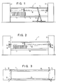
- FIGS. 4 to 8 each show sections through the gripper bar 4 and the spindle bench 8 according to FIG. 2.
- An area is defined above the upper ends of the spindles 7, but still within the outline of full bobbins 13 placed on the spindles a light barrier 10 runs. In this area A, the withdrawal of full bobbins 13 from the spindles 7 can be checked.
- an area B Under the gripping members 5, but still within the outline of empty sleeves 9 held on the gripping members, is an area B. defined, through which a light barrier 10 also runs. In this area B, the release of empty sleeves 9 by the gripping members 5 can be checked by means of the light barrier.
- an area C is defined through which a light barrier 10 runs. In this area, the release of full coils 13 can be checked by the gripping members 5.
- areas B and C coincide with respect to the gripper bars.
- the light barrier 10 defined by the transmitter 11 and the receiver 12 can be displaced in the embodiment according to FIG. 4 over the distance indicated by the arrow I between the two areas A and B / C.
- light barriers are provided for both areas A and B / C on the stationary machine frame, which are formed by two transmitter / receiver pairs 11, 12 and 11 ', 12'.
- the area B / C can only be checked in a specific position of the gripper bar 4, in which this area is located within the machine frame of the ring spinning machine 1.
- the transmitter 11 Sender and the receiver 12 ⁇ forming the light barrier in the area B / C are attached to the gripper bar 4 by means of an arm 21.
- the light barrier for the area B / C is connected to the gripper bar 4; A separate light barrier is provided for area A.
- a gripper bar 4 with separate gripping members 5 or 5 'for full spools 13 or empty sleeves 9 is provided. Accordingly, the three areas A, B and C are to be monitored individually, which in the exemplary embodiment is carried out with a single light barrier with transmitter 11 and receiver 12 in the machine frame or on the gripper bar 4, which can be moved in accordance with the arrows III.
- Fig. 9 shows a side view of a spindle bank 8 and a gripper bar 4 with gripping members 5.
- a transmitter 11 and a receiver 12 are used, the light barrier by four mirrors 16 ', 17', 18 'and 19' between the area A and the area B / C is relocatable.
- the two mirrors 16 'and 17' can be folded out of the beam path.
- both the withdrawal of full bobbins 13 from spindles 7 and the release of empty tubes and full bobbins from the gripping members 5 are monitored by a single transmitter 11 and a single receiver 12.
- FIG. 10 shows a schematic cross section through a ring spinning machine 1 with a transmitter 11 and receiver 12 arranged on the machine frame for the area B / C.
- FIG. 11 shows a cross section through a ring spinning machine 1 with a transmitter 11 or swivel bar 4 shown here. Receiver 12 for the area B / C.
- the corresponding light barriers in this case again run through areas which are occupied by the empty sleeves or full coils to be scanned, but are empty after removal. Since the bobbin changing device in the embodiment according to FIGS. 10 and 11 operates in such a way that the same gripping members grip both empty sleeves 9 and full bobbins 13, regions B and C again coincide.
- FIG. 13 is a schematic illustration of an embodiment in which the three areas A, B and C can be scanned by means of only one displaceable transmitter 11 and one receiver 12.
- a light barrier 10 can be displaced between regions B and C by means of a pair of transmitters / receivers 11, 12 via mirrors.
- This transmitter / receiver pair is arranged, for example, on the gripper bar 4.
- a light barrier 10 ' is provided in this embodiment and is arranged in a fixed position on the machine frame.
- 15 contains a schematic illustration of a solution with which the light barrier 10 can be moved into all three areas A, B and C by means of six mirrors, four of which can be swung out of the beam path, with only one transmitter / receiver pair.
- Figures 16 and 17 contain schematic representations of solutions in which the cheaper part of the transmitter / receiver pair 11, 12 dispenses with the mirrors and this part is provided in multiple numbers compared to the more expensive part. 16 is based on the embodiment according to FIG. 4, FIG. 17 on the embodiment according to FIG. 15. Transmitter and receiver can be interchanged, the transmitter 11 being the more expensive part when using lasers.
- 18 I shows a schematic side view of an embodiment of the invention, from which the arrangement of the areas A, B, C and D can be seen.
- the area A over the spindle tips the area D lies over the holding pin for the empty sleeves 9 ⁇ , both areas being stationary with respect to the machine frame.
- Area B lies under the gripping pins for the empty sleeves;
- area C lies under the gripping pins for the full bobbins; both areas are therefore stationary with respect to the gripper bar 4.
- areas B and C coincide.
- Fig. 18 II a to i shows the individual process steps for monitoring the detection or release of empty sleeves or full bobbins of an automatic bobbin changing device.
- the gripper bar 4 has moved out of its rest position under the spindle bank 8 over the Spindles moves and is in the process of grasping the full bobbins 13 with the gripping members 5 and pulling them off the spindle 7 with the aid of the scissors system 6 until the position according to FIG. 18 II b is reached.
- Below the ring bench 8 is a new empty sleeve 9 ', which is arranged on a support pin 20' mounted on a conveyor belt.
- the light barrier in area A is used to check whether all the full bobbins 13 have actually been removed from the spindles 7. If this is the case, the full coils 13 are moved downward according to FIG. 18 II c and, according to FIG. 18 II d, are pushed onto the holding pins 20.
- the light barrier in area C checks whether all full bobbins have been released and attached to their holding pins 20 on the conveyor belt.
- the gripping members 5 take the empty sleeve 9 ⁇ and pull them from their retaining pins 20 '. Now it is checked by the light barrier in area D whether all empty sleeves 9 'have been tightened by their holding pins 20'. If this is the case, the empty sleeves 9 'are guided in the direction of the arrow into the area above the spindles 7.
- area D is defined via the holding pin 20 'for the empty sleeves 9', but still within the outline of empty sleeves held on these holding pins, which is also penetrated by a light barrier 10. With this light barrier, the withdrawal of empty sleeves 9 'from the holding pin 20' can be monitored.
- This area D assumes that the holding pin 20 'for the empty sleeves 9 ⁇ and the holding pin 20 for the full spools 13 are arranged in separate, laterally offset rows.
- FIG. 18 III there is also the possibility that the light barrier monitoring area A is only activated when the full coils 13 have been moved out of this area. This is advantageous if threads extend in this area in an undesired manner, which would simulate full bobbins 13 which have got caught or got stuck. This avoids undesired working of the individual devices which does not correspond to the actual conditions.
- FIG. 18 III there is also the possibility that a further area E, monitored by a light barrier, is used, which lies in the zone which could be coated by an incorrectly pulled out spindle upper part 30. This also prevents damage to the changing device or other machine elements in a simple manner.
- optical waveguides 23, 24 and 25 are used in order to monitor the corresponding areas via light barriers 10 in order to carry out a correct changeover process.
- These optical waveguides are arranged within an optical waveguide channel, the optical waveguides being at least two-wire.
- One wire works with a light source, not shown, and the other with a photo sensor. The other ends of the two combined wires are directed from the transmitter area 11 to the receiver area 12.
- lasers are suitable for this purpose.
- This system consists of the components light source, light-guiding medium, transmitter and receiver.
- a coherent light source for example a helium-neon laser, can be used as the light source.
- Optical fibers with high transmission in the visible spectral range preferably single-mode glass fibers with a small core diameter, are used as the light-conducting medium.
- An optic serves as a transmitter, which bundles and emits the light emerging from the optical fiber.
- Silicon photo detectors with a large active area and downstream amplifier electronics are used as receivers. This results in the following functionality:
- the light emerging from the laser is split into several partial beams by means of beam splitter plates. Each partial beam meets an optic that maps the light onto the end surface of a glass fiber core.
- the laser light is transmitted through glass fibers of different lengths until it emerges from the fiber at its destination.
- the light now emerging under a very specific fiber-specific opening angle is refocused or parallelized with the aid of further optics, in the simplest case an achromatic lens.
- the beam is expanded and its beam divergence is reduced.
- the expanded beam now bridges the work area to be monitored and finally hits the receiver. This effects a switching function as soon as the light beam is covered by an object, for example an empty sleeve 9 or a full coil 13.
- the laser light barrier system is used to monitor the changing device on the ring spinning machine. In this case, the take-off of full bobbins 13 or the placement or dropping of empty sleeves 9 is again monitored. This process takes about 5 minutes. During this time, the laser is in the operating phase. However, the laser beam is only released for a few seconds, which the measuring process requires.
- Transmitter 11 and receiver 12 are installed at the usual positions and provided with cover panels. On the one hand, these cover panels are intended to suppress extraneous light and, on the other hand, to prevent looking into the laser beam.
Landscapes
- Engineering & Computer Science (AREA)
- Mechanical Engineering (AREA)
- Textile Engineering (AREA)
- Spinning Or Twisting Of Yarns (AREA)
- Replacing, Conveying, And Pick-Finding For Filamentary Materials (AREA)
Claims (19)
- Procédé Pour surveiller la préhension ou la libération, respectivement, de toutes les busettes ou de toutes les bobines, respectivement, d'un dispositif automatique de changement des bobines d'un métier à filer à anneaux ou d'un métier à retordre à anneaux qui, au moyen d'organes de préhension (5), échange simultanément une pluralité de bobines pleines (13) ou de busettes vides entre les broches (7) et les tenons de retenue (20), dans lequel, après avoir retiré les bobines pleines (13) des broches (7), on détermine si toutes les bobines pleines (13) ont été retirées des broches (7) au moyen d'un rayon lumineux photoélectrique passant à travers une zone (A) qui a été occupée par les bobines pleines (13) avant qu'elles n'aient été retirées des broches (7), caractérisé par le fait qu'après la libération des bobines pleines (13) par les organes de préhension (5), on détermine si toutes les bobines pleines (13) ont été libérées par les organes de préhension (5) au moyen d'un rayon lumineux photoélectrique passant à travers une deuxième zone (C) qui a été occupée par les bobines pleines (13) avant leur libération par les organes de préhension (5), et/ou par le fait qu'après avoir retiré les busettes vides (9'') des tenons de retenue (20), on détermine si toutes les busettes vides (9'') ont été retirées des tenons de retenue (20) au moyen d'un rayon lumineux photoélectrique passant à travers une troisième zone (D) qui a été occupée par les busettes vides (9'') avant qu'elles n'aient été retirées des tenons de retenue (20), et/ou par le fait qu'après la libération des busettes vides (9'') par les organes de préhension (5), on détermine si toutes les busettes vides (9'') ont été retirées des organes de préhension (5) au moyen d'un rayon lumineux photoélectrique passant à travers une quatrième zone (B) qui a été occupée par les busettes vides (9'') avant leur libération par les organes de préhension (5).
- Procédé selon la revendication 1, caractérisé par le fait que les rayons lumineux photoélectriques (10) sont activés lorsque les bobines pleines (13) ou les busettes vides (9''), respectivement, auraient dû avoir quitté la zone (A, B, C, D) qui est surveillée par les rayons lumineux photoélectriques (10).
- Procédé selon la revendication 1, caractérisé par le fait qu'une autre zone (E) surveillée par un rayon lumineux photoélectrique est balayée par une partie supérieure de broche (30) qui a été retirée.
- Procédé selon la revendication 1, caractérisé par le fait qu'au moins un émetteur (11, 11', 11'', 11''') et/ou au moins un récepteur (12, 12', 12'', 12''') sont utilisés en vue d'engendrer au moins deux rayons lumineux photoélectriques en des endroits différents.
- Procédé selon la revendication 4, caractérisé par le fait que les rayons lumineux photoélectriques sont engendrés en des endroits différents les uns après les autres.
- Procédé selon les revendications 4 et 5, caractérisé par le fait que les rayons lumineux photoélectriques (10) sont engendrés en des endroits différents par le déplacement du même émetteur (11) et/ou du même récepteur (12) (figures 1 et 2).
- Procédé selon la revendication 4, caractérisé par le fait que les rayons lumineux photoélectriques (10) sont engendrés en des endroits différents par la déviation au moyen d'un miroir du rayon du même émetteur (11) et/ou du même récepteur (12) (figure 3, figure 9).
- Procédé selon la revendication 1, caractérisé par le fait que les deux opérations de détection sur les organes de préhension (5) quant à la libération de toutes les busettes vides (9) ou de toutes les bobines pleines (13), respectivement, ont lieu grâce au fait que la zone (B, C) qui doit être surveillée à chaque fois est amenée au moyen des organes de préhension mobiles (5) dans le même rayon lumineux photoélectrique qui est fixe.
- Dispositif pour la mise en oeuvre du procédé selon la revendication 1, destiné à surveiller la préhension ou la libération, respectivement, de toutes les busettes ou de toutes les bobines, respectivement, d'un dispositif automatique de changement des bobines d'un métier à filer à anneaux ou d'un métier à retordre à anneaux, comprenant des organes de préhension (5) pour échanger simultanément une pluralité de bobines pleines (13) ou de busettes vides entre les broches (7) et les tenons de retenue, et comprenant aussi un rayon lumineux photoélectrique dans une zone déterminée (A), caractérisé par d'autres rayons lumineux photoélectriques (10, 10') qui passent par d'autres zones (B, C, D) traversées par des bobines pleines (13) ou, respectivement, par des busettes vides ou, respectivement, par une partie supérieure de broche (30) qui a été retirée.
- Dispositif selon la revendication 9, caractérisé par le fait qu'un détecteur photoélectrique (10) est disposé sur un élément constitutif (4) qui maintient les organes de préhension (5) (figure 1).
- Dispositif selon la revendication 9, caractérisé par le fait qu'un détecteur photoélectrique (10) est disposé sur un dispositif de déplacement (14, 15), et qu'il peut être déplacé entre les zones (A) des bobines pleines (13) qui sont situées sur les broches (7) et les zones (B/C) des busettes vides (9) ou des bobines pleines (13), respectivement, qui sont saisies par les organes de préhension (5) (figure 2, figure 4).
- Dispositif selon la revendication 11, caractérisé par le fait que le dispositif de déplacement comporte une broche filetée (14) qui est entraînée par un servomoteur (15).
- Dispositif selon la revendication 9, caractérisé par le fait qu'un rayon lumineux photoélectrique peut être amené dans les zones (A) des bobines pleines (13) qui se trouvent sur les broches (7) par le déplacement de l'élément constitutif (4) qui porte les organes de préhension (5) (figure 7).
- Dispositif selon la revendication 9, caractérisé par le fait qu'un rayon lumineux photoélectrique coopère avec des miroirs pivotants (16', 17', 18', 19') qui sont disposés par paires (figure 9).
- Dispositif selon la revendication 14, caractérisé par trois paires de miroirs qui sont disposées dans la zone d'action du rayon lumineux photoélectrique et dont l'une au moins (16', 17') est réalisée en pouvant être effacée par pivotement.
- Dispositif selon l'une des revendications précédentes, caractérisé par le fait que plusieurs paires de miroirs sont associées à plusieurs rayons lumineux photoélectriques (figures 14 à 17).
- Dispositif selon la revendication 9, caractérisé par l'utilisation comme rayon lumineux photoélectrique d'au moins un rayon laser.
- Dispositif selon la revendication 17, caractérisé par une combinaison d'un rayon laser et d'une optique agrandissante comme rayon lumineux.
- Dispositif selon la revendication 9, caractérisé par l'utilisation de conducteurs d'ondes lumineuses dans la zone du rayon lumineux photoélectrique (figures 19 et 20).
Applications Claiming Priority (2)
| Application Number | Priority Date | Filing Date | Title |
|---|---|---|---|
| DE3836330A DE3836330A1 (de) | 1988-10-25 | 1988-10-25 | Verfahren und vorrichtung zum ueberwachen des erfassens bzw. freigebens aller huelsen bzw. spulen einer selbsttaetigen spulenwechselvorrichtung an einer ringspinn- oder -zwirnmaschine |
| DE3836330 | 1988-10-25 |
Publications (2)
| Publication Number | Publication Date |
|---|---|
| EP0366048A1 EP0366048A1 (fr) | 1990-05-02 |
| EP0366048B1 true EP0366048B1 (fr) | 1994-06-01 |
Family
ID=6365881
Family Applications (1)
| Application Number | Title | Priority Date | Filing Date |
|---|---|---|---|
| EP89119656A Expired - Lifetime EP0366048B1 (fr) | 1988-10-25 | 1989-10-23 | Procédé et dispositif pour surveiller les préhension et relâchement de tous les tubes respectivement de toutes les bobines d'un appareil d'échange automatique de bobines d'un métier à filer à anneaux ou d'un métier à retordre à anneaux |
Country Status (4)
| Country | Link |
|---|---|
| US (1) | US5016433A (fr) |
| EP (1) | EP0366048B1 (fr) |
| JP (1) | JPH02160939A (fr) |
| DE (2) | DE3836330A1 (fr) |
Families Citing this family (10)
| Publication number | Priority date | Publication date | Assignee | Title |
|---|---|---|---|---|
| DE4037312C2 (de) * | 1990-11-23 | 1994-03-10 | Zinser Textilmaschinen Gmbh | Vorrichtung zum Greifen einer leeren Hülse oder einer vollen Spule |
| DE4037880C2 (de) * | 1990-11-28 | 1994-06-30 | Zinser Textilmaschinen Gmbh | Verfahren und Vorrichtung zum Überwachen des Spulenwechselvorganges bei einer Spinnereimaschine |
| DE4132243C2 (de) * | 1991-09-27 | 1994-06-16 | Zinser Textilmaschinen Gmbh | Verfahren und Vorrichtung zum Betreiben einer Ringspinn- oder-zwirnmaschine |
| DE4224436C2 (de) * | 1992-07-24 | 1996-11-14 | Zinser Textilmaschinen Gmbh | Doppelseitige Ringspinnmaschine mit Spulenwechselvorrichtung |
| DE4421778C2 (de) * | 1994-06-22 | 1996-11-14 | Zinser Textilmaschinen Gmbh | Vorrichtung zum selbsttätigen Zu- oder Abführen voller Spulen oder leerer Hülsen für eine Textilmaschine |
| DE19631753C2 (de) * | 1996-08-06 | 1999-08-12 | Zinser Textilmaschinen Gmbh | Verfahren zur Kollisionsüberwachung eines bewegbaren Elements einer Spinnereimaschine |
| DE19742154C2 (de) * | 1997-09-24 | 2002-03-07 | Zinser Textilmaschinen Gmbh | Bestückungsüberwachung an einer Vorspinnmaschine |
| JP2002129434A (ja) * | 2000-10-17 | 2002-05-09 | Toyota Industries Corp | 単錘駆動式紡機の管替装置の異常検出方法及び装置 |
| CN104005129B (zh) * | 2014-06-09 | 2016-02-10 | 宜宾惠美精纺科技股份有限公司 | 细纱机集体落纱智能检测控制系统 |
| CN104233535A (zh) * | 2014-08-28 | 2014-12-24 | 湖州丝葳纺织有限公司 | 一种细纱管自动填装装置 |
Family Cites Families (15)
| Publication number | Priority date | Publication date | Assignee | Title |
|---|---|---|---|---|
| CH541636A (de) * | 1971-06-18 | 1973-09-15 | Rieter Ag Maschf | Verfahren und Vorrichtung zum Überwachen des Auswechselns von Kopsen gegen Hülsen auf Spindeln an Ringspinn- und Ringzwirnmaschinen |
| GB1383173A (en) * | 1971-11-18 | 1975-02-05 | Maremont Corp | Donning of bobbins onto spindles or other vertical elements |
| JPS4993624A (fr) * | 1973-01-13 | 1974-09-05 | ||
| DD106469A1 (fr) * | 1973-08-24 | 1974-06-12 | ||
| DE2536435C2 (de) * | 1975-08-16 | 1984-02-23 | W. Schlafhorst & Co, 4050 Mönchengladbach | Verfahren und Vorrichtung zum Auswechseln von Faserbandbehältern |
| FR2427649B1 (fr) * | 1978-05-31 | 1985-10-25 | Hawker Siddeley Dynamics Eng | Systeme de commande pour processus repetitifs industriels |
| JPS5723507U (fr) * | 1980-07-09 | 1982-02-06 | ||
| DE3032584C2 (de) * | 1980-08-29 | 1982-06-24 | Trützschler GmbH & Co KG, 4050 Mönchengladbach | Vorrichtung zur Überwachung und Sicherung von begehbaren Gefahrenbereichen an kraftgetriebenen Textilmaschinen |
| JPS57153203A (en) * | 1981-03-17 | 1982-09-21 | Nitto Shoji Kk | Detection for variance of sliver thickness |
| US4333411A (en) * | 1981-07-15 | 1982-06-08 | The Singer Company | Bobbin thread level detection and display arrangement for a sewing machine |
| DE3306075C1 (de) * | 1983-02-22 | 1984-03-01 | Pfaff Haushaltmaschinen Gmbh, 7500 Karlsruhe | Naehmaschine mit einer Spuleinrichtung |
| JPS59168138A (ja) * | 1983-03-14 | 1984-09-21 | Toyoda Autom Loom Works Ltd | 粗紡機の粗糸巻取張力制御装置 |
| DE3321261C2 (de) * | 1983-06-11 | 1985-10-24 | Rhodia Ag, 7800 Freiburg | Vorrichtung zur Überwachung von drehenden Teilen auf entstehende Wickel bzw. Aufläufe |
| DE3528294A1 (de) * | 1984-08-09 | 1986-02-20 | Daimler-Benz Ag, 7000 Stuttgart | Verfahren zur faseroptischen, spektral kodierten uebertragung des wertes einer veraenderlichen physikalischen messgroesse |
| JPS61178375A (ja) * | 1985-01-31 | 1986-08-11 | Murata Mach Ltd | 精紡機の管理システム |
-
1988
- 1988-10-25 DE DE3836330A patent/DE3836330A1/de not_active Withdrawn
-
1989
- 1989-10-23 DE DE58907768T patent/DE58907768D1/de not_active Expired - Fee Related
- 1989-10-23 EP EP89119656A patent/EP0366048B1/fr not_active Expired - Lifetime
- 1989-10-23 JP JP1273895A patent/JPH02160939A/ja active Pending
- 1989-10-23 US US07/425,428 patent/US5016433A/en not_active Expired - Fee Related
Also Published As
| Publication number | Publication date |
|---|---|
| US5016433A (en) | 1991-05-21 |
| DE3836330A1 (de) | 1990-04-26 |
| JPH02160939A (ja) | 1990-06-20 |
| EP0366048A1 (fr) | 1990-05-02 |
| DE58907768D1 (de) | 1994-07-07 |
Similar Documents
| Publication | Publication Date | Title |
|---|---|---|
| DE2350840C3 (de) | Offenendspinnmaschine mit einer Vielzahl nebeneinander angeordneter Spinnaggregate | |
| EP0366048B1 (fr) | Procédé et dispositif pour surveiller les préhension et relâchement de tous les tubes respectivement de toutes les bobines d'un appareil d'échange automatique de bobines d'un métier à filer à anneaux ou d'un métier à retordre à anneaux | |
| DE3602961A1 (de) | Verfahren und vorrichtung zum warten der arbeitsstellen von spinn- oder zwirnmaschinen mittels mehrerer an den arbeitsstellen entlang fahrbarer wartungseinrichtungen | |
| DE3842120C2 (de) | Verfahren und Vorrichtung zum Herstellen doublierter Fäden | |
| DE3942304A1 (de) | Verfahren und vorrichtung zur qualitativen und quantitativen erfassung eines garnwickels und zum ableiten definierter steuervorgaenge daraus | |
| DE4002343C2 (de) | Vorrichtung zum Spleißen von Doppelfäden | |
| WO1998028217A1 (fr) | Bobineuse a dispositif de guidage | |
| DE68925017T2 (de) | Automatisches Ansetzen eines Faserbandes in einer Textilmaschine. | |
| CH670838A5 (fr) | ||
| DE3022149C2 (fr) | ||
| DE3924946C2 (fr) | ||
| EP1446521B1 (fr) | Machine a texturer | |
| DE3931878C2 (de) | Texturiermaschine | |
| DE3344993A1 (de) | Mehrstellige textilmaschine | |
| DE102005005129B4 (de) | Vorrichtung zum Aufwickeln mehrerer Fadenscharen | |
| DE2546436A1 (de) | Entlang einer spinnmaschine, insbesondere eine offenend-spinnmaschine verfahrbare wartungsvorrichtung | |
| DE102018008062A1 (de) | Verfahren zum Bedienen einer Schmelzspinnvorrichtung sowie eine Schmelzspinnvorrichtung | |
| DE2952400A1 (de) | Verfahren und vorrichtung zum aufspulen einer vielzahl von faeden | |
| DE3941822C2 (de) | Vorrichtung zum Wechseln von Vorgarnspulen | |
| DE4239731A1 (de) | Bestückter Spulenträger | |
| DE4037312A1 (de) | Vorrichtung zum greifen einer leeren huelse oder einer vollen spule | |
| DE2413449C2 (de) | Verfahren zum Wiedereinlegen eines ausgefädelten Fadenlaufs bei einer Hochgeschwindigkeits-Anlage | |
| DE102021129446A1 (de) | Garnspanner, Arbeitsstelle sowie Verfahren zum Betreiben einer Arbeitsstelle | |
| EP0388938A1 (fr) | Procédé pour faire fonctionner un métier à filer et robot de manipulation pour la mise en oeuvre de ce procédé | |
| DE69516590T2 (de) | Verfahren zum unterbrechen der Faserlunte als Voraussetzung für das automatische abheben der Spulen auf Spindelbänken und Pressfinger zur Durchführung dieses Verfahrens |
Legal Events
| Date | Code | Title | Description |
|---|---|---|---|
| PUAI | Public reference made under article 153(3) epc to a published international application that has entered the european phase |
Free format text: ORIGINAL CODE: 0009012 |
|
| AK | Designated contracting states |
Kind code of ref document: A1 Designated state(s): CH DE FR IT LI |
|
| 17P | Request for examination filed |
Effective date: 19900404 |
|
| 17Q | First examination report despatched |
Effective date: 19910913 |
|
| GRAA | (expected) grant |
Free format text: ORIGINAL CODE: 0009210 |
|
| AK | Designated contracting states |
Kind code of ref document: B1 Designated state(s): CH DE FR IT LI |
|
| PG25 | Lapsed in a contracting state [announced via postgrant information from national office to epo] |
Ref country code: FR Effective date: 19940601 |
|
| ITF | It: translation for a ep patent filed | ||
| REF | Corresponds to: |
Ref document number: 58907768 Country of ref document: DE Date of ref document: 19940707 |
|
| EN | Fr: translation not filed | ||
| PLBE | No opposition filed within time limit |
Free format text: ORIGINAL CODE: 0009261 |
|
| STAA | Information on the status of an ep patent application or granted ep patent |
Free format text: STATUS: NO OPPOSITION FILED WITHIN TIME LIMIT |
|
| 26N | No opposition filed | ||
| PGFP | Annual fee paid to national office [announced via postgrant information from national office to epo] |
Ref country code: DE Payment date: 19961213 Year of fee payment: 8 |
|
| PGFP | Annual fee paid to national office [announced via postgrant information from national office to epo] |
Ref country code: CH Payment date: 19970122 Year of fee payment: 8 |
|
| PG25 | Lapsed in a contracting state [announced via postgrant information from national office to epo] |
Ref country code: LI Free format text: LAPSE BECAUSE OF NON-PAYMENT OF DUE FEES Effective date: 19971031 Ref country code: CH Free format text: LAPSE BECAUSE OF NON-PAYMENT OF DUE FEES Effective date: 19971031 |
|
| REG | Reference to a national code |
Ref country code: CH Ref legal event code: PL |
|
| PG25 | Lapsed in a contracting state [announced via postgrant information from national office to epo] |
Ref country code: DE Free format text: LAPSE BECAUSE OF NON-PAYMENT OF DUE FEES Effective date: 19980701 |
|
| PG25 | Lapsed in a contracting state [announced via postgrant information from national office to epo] |
Ref country code: IT Free format text: LAPSE BECAUSE OF NON-PAYMENT OF DUE FEES;WARNING: LAPSES OF ITALIAN PATENTS WITH EFFECTIVE DATE BEFORE 2007 MAY HAVE OCCURRED AT ANY TIME BEFORE 2007. THE CORRECT EFFECTIVE DATE MAY BE DIFFERENT FROM THE ONE RECORDED. Effective date: 20051023 |