EP0366073B1 - Pinion clutch for starter - Google Patents
Pinion clutch for starter Download PDFInfo
- Publication number
- EP0366073B1 EP0366073B1 EP89119731A EP89119731A EP0366073B1 EP 0366073 B1 EP0366073 B1 EP 0366073B1 EP 89119731 A EP89119731 A EP 89119731A EP 89119731 A EP89119731 A EP 89119731A EP 0366073 B1 EP0366073 B1 EP 0366073B1
- Authority
- EP
- European Patent Office
- Prior art keywords
- clutch
- pinion
- spline
- spring
- meshing
- Prior art date
- Legal status (The legal status is an assumption and is not a legal conclusion. Google has not performed a legal analysis and makes no representation as to the accuracy of the status listed.)
- Expired - Lifetime
Links
Images

Classifications
-
- F—MECHANICAL ENGINEERING; LIGHTING; HEATING; WEAPONS; BLASTING
- F02—COMBUSTION ENGINES; HOT-GAS OR COMBUSTION-PRODUCT ENGINE PLANTS
- F02N—STARTING OF COMBUSTION ENGINES; STARTING AIDS FOR SUCH ENGINES, NOT OTHERWISE PROVIDED FOR
- F02N15/00—Other power-operated starting apparatus; Component parts, details, or accessories, not provided for in, or of interest apart from groups F02N5/00 - F02N13/00
- F02N15/02—Gearing between starting-engines and started engines; Engagement or disengagement thereof
- F02N15/022—Gearing between starting-engines and started engines; Engagement or disengagement thereof the starter comprising an intermediate clutch
- F02N15/023—Gearing between starting-engines and started engines; Engagement or disengagement thereof the starter comprising an intermediate clutch of the overrunning type
-
- Y—GENERAL TAGGING OF NEW TECHNOLOGICAL DEVELOPMENTS; GENERAL TAGGING OF CROSS-SECTIONAL TECHNOLOGIES SPANNING OVER SEVERAL SECTIONS OF THE IPC; TECHNICAL SUBJECTS COVERED BY FORMER USPC CROSS-REFERENCE ART COLLECTIONS [XRACs] AND DIGESTS
- Y10—TECHNICAL SUBJECTS COVERED BY FORMER USPC
- Y10T—TECHNICAL SUBJECTS COVERED BY FORMER US CLASSIFICATION
- Y10T74/00—Machine element or mechanism
- Y10T74/13—Machine starters
Definitions
- the present invention relates to a pinion clutch for a starter, and, more particularly, to a pinion clutch capable of improving reliability in pinion meshing and of reducing impact torque which can be generated upon meshing.
- conventional pinion clutches for starters are arranged such that a spline tube is disposed on a drive shaft, the spline tube having a first helical spline on the inner surface thereof and a second helical spline on the outer surface of the same.
- the inner surface of the spline tube is engaged to the drive shaft through the first helical spline, while the outer surface of the spline tube is engaged to a clutch-outer through the second helical spline.
- rollers are disposed between a clutch-inner and the clutch-outer, the clutch-inner being integrally formed with the pinion.
- a pinion clutch having a one-way clutch function is achieved.
- a meshing spring capable of being elastically deformed in the axial direction when the pinion collides with the ring gear of an engine, is disposed between a sleeve and the clutch-outer, the sleeve being capable of moving the pinion clutch in the axial direction.
- Another spring is so disposed between the spline tube and the drive shaft as to be capable of being elastically deformed in the axial direction.
- the second helical spline on the outer surface of the spline tube acts to be meshed with the pinion.
- the function of the helical spline of this type is the same as that of a conventional pinion clutch which is previous to the above described conventional clutch, the helical spline of the previous conventional pinion clutch being of the type capable of causing the clutch-outer to be engaged to the drive shaft through a single helical spline. That is, the torsional direction of the helical spline is arranged to be in the direction opposite to the rotation of the drive shaft.
- the pinion is, by the action of the helical spline, caused to move forward and rotated in the direction opposite to the rotation of the drive shaft to be brought into contact and meshed with the ring gear thereafter.
- the pinion in mesh with the ring gear is caused to further move forward by the action of the helical spline due to the torque of the motor which rotates the drive shaft.
- the first helical spline formed on the inner surface of the spline tube is provided for the purpose of absorbing impact torque which can be generated when the pinion meshes with the ring gear, the helical spline being arranged to be twisted in the same direction as that of the rotation of the drive shaft. Therefore, a clip is used to secure the end portion of the spline tube in order to prevent the spline tube from moving toward the ring gear, such clip being located at the end portion of the spline in the direction in which the spline tube moves.
- the two helical splines respectively formed on the inner and outer surfaces of the spline tube do not act in cooperation with each other when the pinion meshes with the ring gear.
- the helical spline formed on the outer surface acts solely. Similar to the single helical spline of the previous conventional pinion clutch, the conventional helical spline simply causes the pinion to move forward after the pinion has meshed with the ring gear, that is, the helical spline performs a meshing action.
- the conventional helical spline cannot eliminate the possibility of failure in establishing the meshing between the pinion and the ring gear due to a collision. Therefore, reliability in the meshing cannot be improved.
- the above-described conventional pinion clutch has been arranged such that the performance of absorbing impact torque and reliability in pinion meshing are improved by individual means.
- No pinion clutch in which the performance of absorbing impact torque and the reliability in pinion meshing are simultaneously improved has yet been realized.
- an object of the present invention is to provide a pinion clutch for a starter capable of simultaneously improving the performance of absorbing impact torque and reliability in pinion meshing.
- the above-described object can be realized by a structure arranged such that a meshing spring and an impact torque absorbing spring urging the spline tube and the clutch-outer in a direction in which the spline tube and the clutch-outer move away from each other are in series disposed between the spline tube and the clutch-outer, each such spring possessing an individual spring constants.
- the direction of the torsion thereof is arranged to be opposite to that of rotation of the drive shaft.
- the second helical spline formed on the outer surface of the spline tube acts to assist the pinion meshing action and to absorb impact torque, the direction of the torsion thereof being arranged to be the same as that of rotation of the drive shaft.
- the meshing spring is deformed to absorb the axial force when the pinion collides with the ring gear of the engine. Simultaneously, the forward movement of the pinion and the rotation of the same are restricted, causing the spline tube to move forward with respect to the clutch-outer due to the action of the second helical spline formed on the outer surface of the spline tube.
- the clutch-outer is intended to displace itself by a degree of the torsional angle of the second helical spline corresponding to the amount of the relative movement of both the clutch-outer and the spline tube.
- a pinion clutch includes a drive shaft 1 capable of transmitting power of a motor when an engine is started.
- a spline tube 3 capable of transmitting the power to a clutch-outer of the pinion clutch is disposed on the drive shaft 1.
- a first helical spline 4A is formed on the inner surface of the spline tube 3, while another first helical spline 4B is formed on the outer surface of the drive shaft, the first helical spline 4B corresponding to the first helical spline 4A.
- the spline tube 3 is joined to the drive shaft 1 through the first helical splines 4A and 4B.
- a second helical spline 5A is formed on the outer surface of the spline tube 3, while another second helical spline 5B is formed on the inner surface of the clutch-outer 2, the second helical spline 5B corresponding to the second helical spline 5A.
- the spline tube 3 is joined to the clutch-outer 2 through the second helical splines 5A and 5B.
- the first helical splines 4A and 4B are designed such that the torsional direction thereof is arranged to be in the direction opposite to that of the rotation of the drive shaft 1 for the purpose of mainly contributing the pinion meshing action.
- the second helical splines 5A and 5B are designed such that the torsional direction thereof is arranged to be in the same direction as that of the rotation of the drive shaft 1 for the purpose of conducting, as described later, both an assist action of pinion meshing and an impact torque absorbing function.
- a clutch-inner 6 is slidably supported on the drive shaft 1. At an end of the clutch-inner 6 there is provided an integrally formed pinion 8 which is arranged to be meshed with the ring gear 7 of the engine.
- the clutch-outer 2 of the pinion clutch has a profile of the inner surface thereof with which a one-way clutch function can be established. Rollers 9 are disposed between the surface of the profile and the clutch-inner 6.
- the pinion clutch having a one-way clutch function is formed by the clutch-outer 2, the rollers 9, roller pushing springs (not shown), and the clutch-inner 6.
- the meshing spring 10 is a coil spring disposed around the outer surface of the clutch-outer 2.
- the impact torque absorbing spring 11 is a belleville spring disposed around the outer surface of the spline tube 3 and is positioned in contact with and supported by an equalizing ring 12 disposed on an end portion of the spline tube 3 at the circumferential portion of a surface opposite to the clutch-outer 2.
- the equalizing ring 12 is secured by a clip 13 and is arranged so as to bear a load of the impact torque absorbing spring 11 by a flat surface 14 formed on the outer surface thereof.
- a sleeve 15 for moving the whole of the pinion clutch in the axial direction by a shift level (not shown).
- the meshing spring 10 is disposed between the sleeve 15 and the clutch-outer 2 and an end of the sleeve 15 is positioned in contact with and held by the impact torque absorbing spring 11.
- the meshing spring 10 is so arranged as to have the smaller spring constant than that of the impact torque absorbing spring 11 and also to have the maximum spring load smaller than that of the impact torque absorbing spring 11.
- a pinion stopper 17 is provided on the drive shaft and it is secured by a clip 18.
- the pinion stopper 17 serves as a stopper against the movement of the whole of the pinion clutch in the direction of the right as viewed in the drawing due to the movement of the spline tube 3 by the action of the first helical splines 4A and 4B.
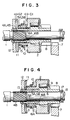
- Fig. 3 is a view which illustrates a starter including the above-described pinion clutch.
- reference numeral 20 represents a magnet switch capable of generating an attracting force when an internal coil thereof is magnetized. The attracting force thus generated acts on a plunger 21 to move it in the direction of the left as viewed in Fig. 2.
- a shift lever 23 is connected to the plunger 21 and it is pivotally supported by a fulcrum 22. A front portion of the shift lever 23 is engaged to the above-described sleeve 15 of the pinion clutch.
- Reference numeral 24 represents a motor arranged such that an output shaft 25 thereof is connected to the drive shaft 1 through a reduction gear 26, and thus the power therefrom is transmitted to the drive shaft 1 through the reduction gear 26.
- the clutch-outer 2 is intended to displace by an angular degree of the torsion of the second helical splines 5A and 5B corresponding to the amount of the relative movement of the clutch-outer 2 and the spline tube 3. Therefore, the pinion 8 integrally formed with the clutch-outer 2 moves in the circumferential direction or a meshing force acts at the crest of the gear. Consequently, the possibility of error in meshing action can be eliminated and reliability in the meshing is improved.
- the pinion 8 moves forward within the ring gear 7 by the actions of the first helical splines 4A and 4B formed on the inner surface of the spline tube 3 until it comes into contact with the pinion stopper 17, so that the pinion 8 is completely meshed with the ring gear 7.
- the pinion clutch acts as shown in Fig. 4.
- the pinion 8 is positioned in contact with the pinion stopper 17.
- the spline tube 3 is intended to move forward in the right direction in the drawing by the actions of the first helical splines 4A and 4B formed on the inner surface of the spline tube 3.
- the clutch-outer 2 is intended to move rearward in the drawing by the actions of the second helical splines 5A and 5B formed on the outer surface of the spline tube 3. Therefore, a thrust force in the direction in which the clutch-outer 3 and the spline tube 2 approach to each other is generated.
- the gap G1 between the clutch-outer 2 and the impact torque absorbing spring 11 is made to be zero.
- a gap corresponding to the gap G1 is created between the stoppers 16A and 16B of the spline tube 3 and the clutch-outer 2.
- the meshing spring 10 having a smaller spring constant is deformed so that the impact torque is initially absorbed.
- the rear surface of the clutch-outer 2 presses, as shown in Fig. 4, the inner portion of the impact torque absorbing spring 11.
- the impact torque absorbing spring 11 is deformed to reduce the size of the gap G2.
- the load corresponding to the spring constant of the impact torque absorbing spring 11 and energy required to deform the same become energy capable of absorbing the impact torque, so that the impact torque can be lightened.
- the meshing spring 10 and the impact torque absorbing spring 11 are, as described above, disposed in series between the clutch-outer 2 and the spline tube 3, errors in meshing of the pinion 8 with the ring gear 8 can be eliminated, that is, reliability in the meshing can be improved and also an excessive impact torque generated after the meshing can be absorbed.
- the shock due to the collision can be further effectively absorbed in comparison with the effect in absorption achieved by a structure in which only the meshing spring acts to absorb the shock, and life can be significantly lengthened.
- the meshing spring 10 contributes to the absorption of the impact torque, the impact torque absorbing performance can be improved.
- both excellent impact torque absorbing performance and reliability in pinion meshing can be achieved. Consequently, the size and weight of the starter can be reduced with an excellent meshing reliability retained.
Landscapes
- Engineering & Computer Science (AREA)
- Chemical & Material Sciences (AREA)
- Combustion & Propulsion (AREA)
- Mechanical Engineering (AREA)
- General Engineering & Computer Science (AREA)
- Mechanical Operated Clutches (AREA)
- Gear Transmission (AREA)
- Connection Of Motors, Electrical Generators, Mechanical Devices, And The Like (AREA)
Applications Claiming Priority (2)
| Application Number | Priority Date | Filing Date | Title |
|---|---|---|---|
| JP63271425A JPH0697027B2 (ja) | 1988-10-27 | 1988-10-27 | スタータのピニオンクラッチ装置 |
| JP271425/88 | 1988-10-27 |
Publications (3)
| Publication Number | Publication Date |
|---|---|
| EP0366073A2 EP0366073A2 (en) | 1990-05-02 |
| EP0366073A3 EP0366073A3 (en) | 1990-11-07 |
| EP0366073B1 true EP0366073B1 (en) | 1992-05-13 |
Family
ID=17499856
Family Applications (1)
| Application Number | Title | Priority Date | Filing Date |
|---|---|---|---|
| EP89119731A Expired - Lifetime EP0366073B1 (en) | 1988-10-27 | 1989-10-24 | Pinion clutch for starter |
Country Status (4)
| Country | Link |
|---|---|
| US (1) | US5018611A (ja) |
| EP (1) | EP0366073B1 (ja) |
| JP (1) | JPH0697027B2 (ja) |
| DE (1) | DE68901524D1 (ja) |
Families Citing this family (12)
| Publication number | Priority date | Publication date | Assignee | Title |
|---|---|---|---|---|
| JP4155115B2 (ja) * | 2003-06-10 | 2008-09-24 | 株式会社デンソー | スタータ |
| DE10329585A1 (de) * | 2003-06-30 | 2005-01-27 | Robert Bosch Gmbh | Starter für eine Brennkraftmaschine |
| JP4148062B2 (ja) * | 2003-08-07 | 2008-09-10 | トヨタ自動車株式会社 | 内燃機関の始動装置 |
| WO2006016668A1 (en) * | 2004-08-09 | 2006-02-16 | Toyota Jidosha Kabushiki Kaisha | Starting apparatus |
| JP2011236776A (ja) * | 2010-05-07 | 2011-11-24 | Mitsubishi Electric Corp | エンジン始動装置 |
| JP5580221B2 (ja) * | 2011-02-07 | 2014-08-27 | 株式会社ミツバ | スタータ |
| JP5965268B2 (ja) * | 2011-11-29 | 2016-08-03 | 株式会社ミツバ | スタータ |
| CN102705129A (zh) * | 2012-04-26 | 2012-10-03 | 锦州汉拿电机有限公司 | 具有缓冲装置的汽车用起动机单向器 |
| CN105247235A (zh) * | 2013-05-28 | 2016-01-13 | 舍弗勒技术股份两合公司 | 具有齿轮推力激活装置的楔式单向离合器 |
| CN104234901B (zh) | 2013-06-13 | 2016-08-24 | 株式会社美姿把 | 起动器 |
| JP6069110B2 (ja) * | 2013-06-13 | 2017-02-01 | 株式会社ミツバ | スタータ |
| US10364524B2 (en) * | 2016-04-08 | 2019-07-30 | Whirlpool Corporation | Laundry treating appliance with helical clutch |
Family Cites Families (11)
| Publication number | Priority date | Publication date | Assignee | Title |
|---|---|---|---|---|
| US2117230A (en) * | 1936-07-08 | 1938-05-10 | Gen Motors Corp | Engine starting apparatus |
| US2871708A (en) * | 1955-11-22 | 1959-02-03 | Gen Motors Corp | Starting apparatus for internal combustion engines |
| US3327821A (en) * | 1965-12-17 | 1967-06-27 | Bendix Corp | Engine starter drive |
| US3714834A (en) * | 1971-03-12 | 1973-02-06 | Bendix Corp | Engine starting gearing |
| US3686961A (en) * | 1971-05-17 | 1972-08-29 | Gen Motors Corp | Starting mechanism |
| JPS5430061B2 (ja) * | 1973-09-25 | 1979-09-27 | ||
| JPS5274748A (en) * | 1975-12-17 | 1977-06-23 | Hitachi Ltd | Buffer of roller clutch for starter |
| JPS5430061A (en) * | 1977-08-10 | 1979-03-06 | Hitachi Ltd | Illuminating device |
| JPS6053786B2 (ja) * | 1979-12-24 | 1985-11-27 | 沢藤電機株式会社 | エンジンの始動装置 |
| JPS6039493U (ja) * | 1983-08-26 | 1985-03-19 | ぺんてる株式会社 | ロボツトのワ−ク把持圧入装置 |
| JPS6118224U (ja) * | 1984-07-09 | 1986-02-01 | パイオニア株式会社 | 部品供給装置 |
-
1988
- 1988-10-27 JP JP63271425A patent/JPH0697027B2/ja not_active Expired - Fee Related
-
1989
- 1989-10-24 US US07/426,049 patent/US5018611A/en not_active Expired - Lifetime
- 1989-10-24 EP EP89119731A patent/EP0366073B1/en not_active Expired - Lifetime
- 1989-10-24 DE DE8989119731T patent/DE68901524D1/de not_active Expired - Lifetime
Also Published As
| Publication number | Publication date |
|---|---|
| EP0366073A2 (en) | 1990-05-02 |
| US5018611A (en) | 1991-05-28 |
| DE68901524D1 (de) | 1992-06-17 |
| EP0366073A3 (en) | 1990-11-07 |
| JPH02119675A (ja) | 1990-05-07 |
| JPH0697027B2 (ja) | 1994-11-30 |
Similar Documents
| Publication | Publication Date | Title |
|---|---|---|
| EP0366073B1 (en) | Pinion clutch for starter | |
| US5199309A (en) | Starter unit | |
| JPS6053786B2 (ja) | エンジンの始動装置 | |
| JP2007504413A (ja) | 回転可能体を連結するためのカップリング装置およびカップリング装置を含む変速システム | |
| US4941366A (en) | Coaxial type starter device | |
| US6931953B2 (en) | Starter having small diameter front housing for installation from transmission side | |
| US4744258A (en) | Non-indexing engine starter gearing | |
| US5129270A (en) | Starter with speed reduction mechanism | |
| JPS59151624A (ja) | 車両の動力伝達系における捩り振動吸収装置 | |
| US4019393A (en) | Engine starter gearing | |
| GB2386398A (en) | Starter for an internal combustion engine with an intermediate gear and biasing means to prevent axial movement of the gear | |
| JP4513450B2 (ja) | アクチュエータ | |
| JP2007071164A (ja) | スタータ | |
| US10895238B2 (en) | Starter for internal combustion engine | |
| JPS61157851A (ja) | ダンパ構造 | |
| US8567364B2 (en) | Starter equipped with planetary speed reducer and shock absorber | |
| JPS6221747Y2 (ja) | ||
| JP7477016B1 (ja) | シザーズギア及び伝達機構 | |
| JP2699609B2 (ja) | 慣性飛込式スタータ | |
| JPH0286962A (ja) | 減速機構付スタータ | |
| JP3568996B2 (ja) | 自動変速機の円錐ブレーキ | |
| JPS609415Y2 (ja) | 減速型スタ−タ | |
| JP2959196B2 (ja) | エンジン始動装置 | |
| JPS6146464A (ja) | 遊星歯車減速機構付スタ−タ | |
| JPS5950227A (ja) | クラツチ装置 |
Legal Events
| Date | Code | Title | Description |
|---|---|---|---|
| PUAI | Public reference made under article 153(3) epc to a published international application that has entered the european phase |
Free format text: ORIGINAL CODE: 0009012 |
|
| AK | Designated contracting states |
Kind code of ref document: A2 Designated state(s): DE GB |
|
| PUAL | Search report despatched |
Free format text: ORIGINAL CODE: 0009013 |
|
| AK | Designated contracting states |
Kind code of ref document: A3 Designated state(s): DE GB |
|
| 17P | Request for examination filed |
Effective date: 19901106 |
|
| 17Q | First examination report despatched |
Effective date: 19910206 |
|
| GRAA | (expected) grant |
Free format text: ORIGINAL CODE: 0009210 |
|
| AK | Designated contracting states |
Kind code of ref document: B1 Designated state(s): DE GB |
|
| REF | Corresponds to: |
Ref document number: 68901524 Country of ref document: DE Date of ref document: 19920617 |
|
| PLBE | No opposition filed within time limit |
Free format text: ORIGINAL CODE: 0009261 |
|
| STAA | Information on the status of an ep patent application or granted ep patent |
Free format text: STATUS: NO OPPOSITION FILED WITHIN TIME LIMIT |
|
| 26N | No opposition filed | ||
| REG | Reference to a national code |
Ref country code: GB Ref legal event code: IF02 |
|
| PGFP | Annual fee paid to national office [announced via postgrant information from national office to epo] |
Ref country code: GB Payment date: 20030924 Year of fee payment: 15 |
|
| PGFP | Annual fee paid to national office [announced via postgrant information from national office to epo] |
Ref country code: DE Payment date: 20031203 Year of fee payment: 15 |
|
| PG25 | Lapsed in a contracting state [announced via postgrant information from national office to epo] |
Ref country code: GB Free format text: LAPSE BECAUSE OF NON-PAYMENT OF DUE FEES Effective date: 20041024 |
|
| PG25 | Lapsed in a contracting state [announced via postgrant information from national office to epo] |
Ref country code: DE Free format text: LAPSE BECAUSE OF NON-PAYMENT OF DUE FEES Effective date: 20050503 |
|
| GBPC | Gb: european patent ceased through non-payment of renewal fee |
Effective date: 20041024 |