EP0366098B1 - Détecteur de gaz - Google Patents
Détecteur de gaz Download PDFInfo
- Publication number
- EP0366098B1 EP0366098B1 EP89119771A EP89119771A EP0366098B1 EP 0366098 B1 EP0366098 B1 EP 0366098B1 EP 89119771 A EP89119771 A EP 89119771A EP 89119771 A EP89119771 A EP 89119771A EP 0366098 B1 EP0366098 B1 EP 0366098B1
- Authority
- EP
- European Patent Office
- Prior art keywords
- gas
- layer
- gas detector
- electrode
- solid electrolyte
- Prior art date
- Legal status (The legal status is an assumption and is not a legal conclusion. Google has not performed a legal analysis and makes no representation as to the accuracy of the status listed.)
- Expired - Lifetime
Links
Images

Classifications
-
- H—ELECTRICITY
- H01—ELECTRIC ELEMENTS
- H01H—ELECTRIC SWITCHES; RELAYS; SELECTORS; EMERGENCY PROTECTIVE DEVICES
- H01H33/00—High-tension or heavy-current switches with arc-extinguishing or arc-preventing means
- H01H33/02—Details
- H01H33/53—Cases; Reservoirs, tanks, piping or valves, for arc-extinguishing fluid; Accessories therefor, e.g. safety arrangements, pressure relief devices
- H01H33/56—Gas reservoirs
-
- H—ELECTRICITY
- H01—ELECTRIC ELEMENTS
- H01H—ELECTRIC SWITCHES; RELAYS; SELECTORS; EMERGENCY PROTECTIVE DEVICES
- H01H33/00—High-tension or heavy-current switches with arc-extinguishing or arc-preventing means
- H01H33/02—Details
- H01H33/53—Cases; Reservoirs, tanks, piping or valves, for arc-extinguishing fluid; Accessories therefor, e.g. safety arrangements, pressure relief devices
- H01H33/56—Gas reservoirs
- H01H2033/567—Detection of decomposition products of the gas
Definitions
- the present invention relates generally to a gas detector for detecting the decomposed SF6 gas produced by electric discharching in a gas-insulated equipment.
- a wet method or a dry method is known as a conventional method for detecting the decomposed SF6 gas produced by discharge in gas-insulated equipment.
- decomposed SF6 gas produced by discharge such as SF4 absorbed in alkali-absorbing solution is detected as ions of fluorine by an absorptiometric method (JAPAN ANALYST Vol. 16, P44 (1967)).
- the wet method needs many equipment such as a gas-liquid contact equipment for absorbing decomposed SF6 gas in the absorbing solution and an absorptiometer for measuring fluorine ion or a titrator (cf. a buret) for measuring component in the absorbing solution.
- a gas-liquid contact equipment for absorbing decomposed SF6 gas in the absorbing solution
- an absorptiometer for measuring fluorine ion or a titrator (cf. a buret) for measuring component in the absorbing solution.
- a gas detecting tube which encloses an element showing coloration by reaction with the integrated SF6 gas is shown in Japanese examined publication Tokko sho 57-38091.
- the gas detecting tube of the dry method is small-sized and light weight and enables easy measurement.
- the dry method is easy to carry out the measurement, it has been necessary a man who observes the coloration, since the gas detecting tube has no conversion function from change of the coloration to an electric signal. Thus it is not suitable for use of unmanned continuous measurement.
- a film permeable to the decomposed SF6 gas is used for introducing the decomposed SF6 gas. And introduced decomposed SF6 gas is detected as an electric signal.
- FR-A-2272395 discloses detection of gas content utilizing an oxygen ion conductive solid electrolyte oparable at temperatures of 400 - 900 °C. It is difficult to obtain high sensitivity (e.g. about 0.03 ppm as a HF (gas)) which is required in detection of decomposed SF6 gas.
- US-A-4661211 discloses a gas sensor utilizing hydrogen ion conductive solid electrolyte. In contrast, in detection of decomposed gas of SF6, a reaction of a halogen or halogen compound is to be used.
- the object of the present invention is to provide a gas detector which is small-sized and light weighted and enabling easy measurement of decomposed SF6 gas amount by an electric signal.
- a gas detector in accordance with the present invention comprising; a detecting electrode having a surface exposed to objective gas and containing at least a metal element, an ionic conductive solid electrolyte layer which is formed on said detecting electrode and contains ions of said metal element, an opposing electrode which is formed on said ionic conductive solid electrolyte layer and contains said metal element, an insulative support means supporting said detecting electrode, said ionic conductive solid electrolyte layer and said opposing electrode, and isolating said ionic conductive solid electrolyte layer from said opposing electrode from gas, a first electric terminal connected with said detecting electrode and, a second electric terminal connected with said opposing electrode.
- the gas detector operates as a cell for generating voltage in proportion to amount of the decomposed SF6 gas.
- the voltage is generated between the detecting electrode for reacting with the integrated gas and the opposing electrode wherein both electrodes are sandwiching the ionic conductive electrolyte layer therebetween.
- FIG.1 is a sectional view showing a gas detector embodying the present invention.
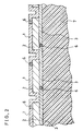
- FIG.2 is a sectional view showing a gas detector integration embodying the present invention.
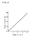
- FIG.3 is a graph showing a relation of the output voltage of the gas detector integration and the number of cells therein.
- a first preferred embodiment of the present invention is elucidated hereafter with reference to FIG.1.
- a detecting electrode 1 which is made of deposition layer of Ag for reacting with the decomposed SF6 gas and an opposing electrode 3 which is also made of deposition layer of Ag, and an ionic conductive solid electrolyte layer 2 such as Ag3SI including Ag ion sandwiched between the each other opposing electrodes 1 and 3.
- an ionic conductive solid electrolyte layer 2 such as Ag3SI including Ag ion sandwiched between the each other opposing electrodes 1 and 3.
- the opposing electrode 3 and the ionic conductive solid electrolyte layer 2 are formed on the substrate 7 which is made of alumina, and further the opposing electrode 3 and the layer 2 are surrounded with the insulator 6 and/or the detecting electrode 1, there is no exposed surface of the opposing electrode 3 to SF6 gas atmosphere. Thereby, only the outside surface of the detecting electrode 1 is exposed to SF6 gas atmosphere.
- SF6 gas is decomposed into SF4 gas, SF2 gas, F(fluorine) and/or S(sulfur).
- the opposing electrode 3 about 3»m thick Ag layer 3 is formed on the substrate 7 made of alumina by sputtering or deposition.
- the Ag layer on the substrates is reacted with mixed gas of hydrogen sulfide and air in volume ratio of about 1 : 3 at about 200°C. In this heat reaction, the surface of the Ag layer is converted to silver sulfide.
- the substrate 7 is put in a closed vessel together with iodine. Reaction period with iodine is controlled so that iodine as silver iodine is contained in the ratio of 1 : 1 on silver sulfide, by measuring the weight increase of the substrate 7.
- the substrate 7 is heated in N2 gas at a temperature of 300°C ⁇ 400°C.
- the surface of the Ag layer is converted finally to the Ag3SI layer for the solid electrolyte layer 2.
- the depth of the Ag composed layer produced by the reaction namely the thickness of the Ag3SI layer is controlled to be about 2»m changing condition such as period and temperature of the above-mentioned reactions on the basis of data given by experiments.
- Ag layer of about 1»m thickness for detection electrode 1 is formed layer by sputtering or deposition on the Ag3SI.
- the substrate 7 is cut to obtain desired size as a gas detector. After boning Au wires as leads 4, 4 and terminals 5, 5 for both electrodes 1 and 3, alumina layer as insulator 6 is formed by sputtering while masking the surface of the detecting electrode 1.
- a second preferred embodiment of the present invention is elucidated hereafter with reference to FIG.2 and FIG.3.
- FIG. 2 a grouped gas detector integration comprising at two or more gas detectors is shown. Corresponding parts and components to the first embodiment are shown by the same numerals and marks, and the description thereon made in the first embodiment similarly apply. Differences and features of this second embodiment from the first embodiment are as follows.
- the gas detector integration has a constitution of a row of cells of FIG. 1, and electric serial connection is made by connecting detection electrodes 1, 1, --- with respective opposing electrodes 3, 3 --- of next cells, like a series connected accumulated battery.
- An output voltage of the gas detector integration is multiplied by the number of cells therein.
- a relation of the output voltage of the gas detector integration and the numbers of the series connected cells therein is shown in FIG.3.
- the method for making the gas detector integration is substantially the same as the above-mentioned method of the first embodiment.
- ions of Ag are carriers of electric charge, since both electrodes comprises Ag and solid electrolyte is made of Ag3SI.
- An electric conductor of mixed metal ion and electron such as Ag2S or Ag x Mo8S8 wich is an electric conductor of mixed Ag ions and electrons can be used for material of electrodes 1 and 3.
- other Ag ion conductive solid electrolyte such as Ag4RbI5 or Ag6IWO4 can be used for the ionic conductive solid electrolyte layer 2.
- Cu ions can be used as carrier of electric charge, and in this case both electrodes are made of a compound of Cu.
- the detecting electrode 1 is made of Cu
- the opposing electrode 3 is made of copper sulfide (Cu2S)
- the ionic conductive solid electrolyte layer 2 is made of Rb4Cu16I7CI13.
Landscapes
- Measuring Oxygen Concentration In Cells (AREA)
- Investigating Or Analyzing Materials By The Use Of Fluid Adsorption Or Reactions (AREA)
Claims (6)
- Détecteur de gaz comprenant :
une électrode (1) de détection ayant une surface exposée à un gaz objectif et contenant au moins un élément métallique,
une couche (2) d'électrolyte solide conductrice ionique formée sur ladite électrode (1) de détection et contenant des ions dudit élément métallique,
une électrode (3) d'opposition qui est formée sur ladite couche (2) d'électrolyte solide conductrice ionique et qui contient ledit élément métallique,
un moyen (7) de support isolant supportant ladite électrode (1) de détection, ladite couche (2) d'électrolyte solide conductrice ionique et ladite électrode (3) d'opposition et isolant ladite couche d'électrolyte solide conductrice ionique de ladite électrode d'opposition du gaz,
un premier terminal (5) électrique connecté avec ladite électrode (1) de détection et,
un second terminal (5) électrique connecté avec ladite électrode (3) d'opposition. - Détecteur de gaz selon la revendication 1 qui comprend de plus au moins deux ou plus desdits détecteurs de gaz tels que revendiqués en revendication 1 où ladite électrode (1) de détection d'un détecteur de gaz est connectée à ladite électrode (3) d'opposition d'un détecteur de gaz suivant pour une connexion en série.
- Détecteur de gaz selon la revendication 1 ou 2 dans lequel ladite électrode (1) de détection est un conducteur électrique d'un électron et d'un ion métallique mixte.
- Détecteur de gaz selon la revendication 1, 2 ou 3 dans lequel ledit élément métallique est Ag.
- Détecteur de gaz selon la revendication 1, 2 ou 3 dans lequel ledit élément métallique est Cu.
- Procédé pour fabriquer un détecteur de gaz comprenant les étapes de :
former une première couche (3) de Ag sur un substrat (7);
convertir la surface de ladite couche de Ag en AgS;
contenir I dans ladite couche de Ag et AgS tel que AgI;
convertir lesdits AgI et AgS en Ag₃SI;
former une seconde couche (1) de Ag sur ladite couche (2) de Ag₃SI;
lier les fils (4) sur chaque dite première et seconde couche de Ag; et
former une couche d'alumine (6) sauf sur la surface de ladite seconde couche (1) de Ag.
Applications Claiming Priority (2)
| Application Number | Priority Date | Filing Date | Title |
|---|---|---|---|
| JP63267392A JPH02114168A (ja) | 1988-10-24 | 1988-10-24 | ガスセンサー |
| JP267392/88 | 1988-10-24 |
Publications (3)
| Publication Number | Publication Date |
|---|---|
| EP0366098A2 EP0366098A2 (fr) | 1990-05-02 |
| EP0366098A3 EP0366098A3 (fr) | 1991-07-03 |
| EP0366098B1 true EP0366098B1 (fr) | 1994-07-13 |
Family
ID=17444211
Family Applications (1)
| Application Number | Title | Priority Date | Filing Date |
|---|---|---|---|
| EP89119771A Expired - Lifetime EP0366098B1 (fr) | 1988-10-24 | 1989-10-24 | Détecteur de gaz |
Country Status (4)
| Country | Link |
|---|---|
| US (1) | US5128020A (fr) |
| EP (1) | EP0366098B1 (fr) |
| JP (1) | JPH02114168A (fr) |
| DE (1) | DE68916743T2 (fr) |
Families Citing this family (8)
| Publication number | Priority date | Publication date | Assignee | Title |
|---|---|---|---|---|
| US5322611A (en) * | 1991-01-31 | 1994-06-21 | Solomon Zaromb | Humidity-resistant ambient-temperature solid-electrolyte amperometric sensing apparatus |
| JP3340028B2 (ja) * | 1996-07-12 | 2002-10-28 | 三菱電機株式会社 | ガスセンサ |
| GB2348006B (en) * | 1999-03-19 | 2003-07-23 | Alphasense Ltd | Gas sensor |
| KR100523516B1 (ko) * | 2003-07-07 | 2005-10-25 | 엘지전자 주식회사 | 박막형 이산화탄소 가스 센서 |
| EP2115402A2 (fr) * | 2007-02-16 | 2009-11-11 | Ceramatec, Inc. | Capteur de no<sb>x</sb>à sélectivité et sensibilité améliorées |
| US9164080B2 (en) | 2012-06-11 | 2015-10-20 | Ohio State Innovation Foundation | System and method for sensing NO |
| JP6233511B2 (ja) * | 2014-06-09 | 2017-11-22 | 富士通株式会社 | ガスセンサー、及びセンサー装置 |
| JP6511957B2 (ja) | 2015-05-22 | 2019-05-15 | 富士通株式会社 | ガスセンサ及び情報処理システム |
Family Cites Families (8)
| Publication number | Priority date | Publication date | Assignee | Title |
|---|---|---|---|---|
| FR2272395A1 (en) * | 1974-05-23 | 1975-12-19 | Quebec Inst Rech Hydro | Measurement of anhydride gases in air - using solid state detector element |
| GB1588828A (en) * | 1978-01-11 | 1981-04-29 | Westinghouse Electric Corp | Sulpur hexafluoride gas-insulated electrical equipment |
| US4188266A (en) * | 1978-04-11 | 1980-02-12 | Forman Richard A | Method and apparatus for changing the concentration of molecules or atoms |
| JPS58195427A (ja) * | 1982-05-11 | 1983-11-14 | 株式会社富士電機総合研究所 | ガス絶縁電気機器の異常検知装置 |
| US4661211A (en) * | 1985-07-10 | 1987-04-28 | Uop Inc. | Gas detection with three-component membrane and sensor using said membrane |
| JPS62207952A (ja) * | 1986-03-10 | 1987-09-12 | Mitsubishi Electric Corp | ガスセンサ− |
| JPS63311164A (ja) * | 1987-06-15 | 1988-12-19 | Mitsubishi Electric Corp | 腐食性ガス検出器 |
| US4886584A (en) * | 1988-06-27 | 1989-12-12 | Solar Scientific, Inc. | Potential measuring method and apparatus having signal amplifying multiple membrane electrode |
-
1988
- 1988-10-24 JP JP63267392A patent/JPH02114168A/ja active Pending
-
1989
- 1989-10-24 DE DE68916743T patent/DE68916743T2/de not_active Expired - Fee Related
- 1989-10-24 EP EP89119771A patent/EP0366098B1/fr not_active Expired - Lifetime
-
1991
- 1991-03-04 US US07/664,429 patent/US5128020A/en not_active Expired - Fee Related
Also Published As
| Publication number | Publication date |
|---|---|
| EP0366098A2 (fr) | 1990-05-02 |
| EP0366098A3 (fr) | 1991-07-03 |
| DE68916743T2 (de) | 1994-11-17 |
| DE68916743D1 (de) | 1994-08-18 |
| US5128020A (en) | 1992-07-07 |
| JPH02114168A (ja) | 1990-04-26 |
Similar Documents
| Publication | Publication Date | Title |
|---|---|---|
| Odziemkowski et al. | A Raman microprobe in situ and ex situ study of film formation at lithium/organic electrolyte interfaces | |
| Odziemkowski et al. | An electrochemical study of the reactivity at the lithium electrolyte/bare lithium metal interface: I. Purified electrolytes | |
| Schlaikjer et al. | Discharge reaction mechanisms in Li/SOCl2 cells | |
| EP0114102B1 (fr) | Appareil pour la détection électrochimique et la titration coulométrique | |
| US5128020A (en) | Gas detector | |
| Genies et al. | In situ conductivity and photoconductivity measurements of polyaniline films | |
| Venkatasetty et al. | Properties of LiAlCl4‐SOCl2 Solutions for Li/SOCl2 Battery | |
| Otsuka et al. | Activities of oxygen in liquid Bi, Sn, and Ge from electrochemical measurements | |
| JPH04238815A (ja) | フッ化物イオン伝導体およびそれを用いた電気化学素子 | |
| Madou et al. | Investigation of SOCl2 reduction by cyclic voltammetry and ac impedance measurements | |
| Jacob et al. | Sulphur potential measurements with a two-phase sulphideoxide electrolyte | |
| US3314863A (en) | Gas analysis | |
| Fritz et al. | Electronic conductivity of Na β ″-alumina ceramics at high temperatures | |
| Takada et al. | On the Graphite Intercalation Compound Prepared Electrochemically in LiClO4-Propylene Carbonate Electrolyte | |
| US5552025A (en) | Sensors | |
| Carter et al. | Heterogeneous and homogeneous electron transfer reactions of tetrathiafulvalene in ambient temperature chloroaluminate molten salts | |
| JPH0560547B2 (fr) | ||
| Fang et al. | The Electrical Conductivity of β‐PbF2 | |
| Uchida et al. | Titanium Dioxide Electrode in Molten Sodium Tetrachloroaluminate; Photocurrent and Flatband Potential | |
| Hoare et al. | On the Transference Number for Li+ Ion in Propylene Carbonate Solutions from EMF Measurements | |
| Kumar et al. | Performance Characteristics of Magnesium/para‐Nitrophenol Cells in 2: 1 Magnesium Electrolytes | |
| JPH0566215A (ja) | ガスセンサ | |
| Quickenden et al. | The power conversion efficiency of the thionine photoelectrochemical cell containing uncoated and thionine coated photoelectrodes | |
| SALMON et al. | Li/SOC12 BATTERIES DURING ANODE LIMITED CELL REVERSAL | |
| SU911299A1 (ru) | Способ определени коэффициента диффузии кислорода в металлах и окислах |
Legal Events
| Date | Code | Title | Description |
|---|---|---|---|
| PUAI | Public reference made under article 153(3) epc to a published international application that has entered the european phase |
Free format text: ORIGINAL CODE: 0009012 |
|
| 17P | Request for examination filed |
Effective date: 19891024 |
|
| AK | Designated contracting states |
Kind code of ref document: A2 Designated state(s): CH DE GB LI SE |
|
| PUAL | Search report despatched |
Free format text: ORIGINAL CODE: 0009013 |
|
| AK | Designated contracting states |
Kind code of ref document: A3 Designated state(s): CH DE GB LI SE |
|
| 17Q | First examination report despatched |
Effective date: 19930402 |
|
| GRAA | (expected) grant |
Free format text: ORIGINAL CODE: 0009210 |
|
| AK | Designated contracting states |
Kind code of ref document: B1 Designated state(s): CH DE GB LI SE |
|
| REF | Corresponds to: |
Ref document number: 68916743 Country of ref document: DE Date of ref document: 19940818 |
|
| REG | Reference to a national code |
Ref country code: GB Ref legal event code: 727 |
|
| EAL | Se: european patent in force in sweden |
Ref document number: 89119771.7 |
|
| REG | Reference to a national code |
Ref country code: GB Ref legal event code: 727A |
|
| PLBE | No opposition filed within time limit |
Free format text: ORIGINAL CODE: 0009261 |
|
| STAA | Information on the status of an ep patent application or granted ep patent |
Free format text: STATUS: NO OPPOSITION FILED WITHIN TIME LIMIT |
|
| REG | Reference to a national code |
Ref country code: GB Ref legal event code: 727B |
|
| 26N | No opposition filed | ||
| REG | Reference to a national code |
Ref country code: GB Ref legal event code: SP |
|
| REG | Reference to a national code |
Ref country code: GB Ref legal event code: 746 Effective date: 19951106 |
|
| PGFP | Annual fee paid to national office [announced via postgrant information from national office to epo] |
Ref country code: CH Payment date: 19991027 Year of fee payment: 11 |
|
| PGFP | Annual fee paid to national office [announced via postgrant information from national office to epo] |
Ref country code: SE Payment date: 20001009 Year of fee payment: 12 |
|
| PGFP | Annual fee paid to national office [announced via postgrant information from national office to epo] |
Ref country code: DE Payment date: 20001016 Year of fee payment: 12 |
|
| PGFP | Annual fee paid to national office [announced via postgrant information from national office to epo] |
Ref country code: GB Payment date: 20001018 Year of fee payment: 12 |
|
| PG25 | Lapsed in a contracting state [announced via postgrant information from national office to epo] |
Ref country code: LI Free format text: LAPSE BECAUSE OF NON-PAYMENT OF DUE FEES Effective date: 20001031 Ref country code: CH Free format text: LAPSE BECAUSE OF NON-PAYMENT OF DUE FEES Effective date: 20001031 |
|
| REG | Reference to a national code |
Ref country code: CH Ref legal event code: PL |
|
| PG25 | Lapsed in a contracting state [announced via postgrant information from national office to epo] |
Ref country code: GB Free format text: LAPSE BECAUSE OF NON-PAYMENT OF DUE FEES Effective date: 20011024 |
|
| PG25 | Lapsed in a contracting state [announced via postgrant information from national office to epo] |
Ref country code: SE Free format text: LAPSE BECAUSE OF NON-PAYMENT OF DUE FEES Effective date: 20011025 |
|
| REG | Reference to a national code |
Ref country code: GB Ref legal event code: IF02 |
|
| EUG | Se: european patent has lapsed |
Ref document number: 89119771.7 |
|
| GBPC | Gb: european patent ceased through non-payment of renewal fee |
Effective date: 20011024 |
|
| PG25 | Lapsed in a contracting state [announced via postgrant information from national office to epo] |
Ref country code: DE Free format text: LAPSE BECAUSE OF NON-PAYMENT OF DUE FEES Effective date: 20020702 |