EP0366110A2 - Method for manufacturing a fiber type coupler - Google Patents
Method for manufacturing a fiber type coupler Download PDFInfo
- Publication number
- EP0366110A2 EP0366110A2 EP89119834A EP89119834A EP0366110A2 EP 0366110 A2 EP0366110 A2 EP 0366110A2 EP 89119834 A EP89119834 A EP 89119834A EP 89119834 A EP89119834 A EP 89119834A EP 0366110 A2 EP0366110 A2 EP 0366110A2
- Authority
- EP
- European Patent Office
- Prior art keywords
- coupler
- fiber type
- tension
- manufacturing
- optical axis
- Prior art date
- Legal status (The legal status is an assumption and is not a legal conclusion. Google has not performed a legal analysis and makes no representation as to the accuracy of the status listed.)
- Granted
Links
- 239000000835 fiber Substances 0.000 title claims abstract description 63
- 238000004519 manufacturing process Methods 0.000 title claims abstract description 34
- 238000000034 method Methods 0.000 title claims abstract description 30
- 239000013307 optical fiber Substances 0.000 claims abstract description 42
- 230000003287 optical effect Effects 0.000 claims abstract description 30
- 230000001681 protective effect Effects 0.000 claims abstract description 12
- 238000000576 coating method Methods 0.000 claims abstract description 7
- 238000010438 heat treatment Methods 0.000 claims description 8
- 238000005259 measurement Methods 0.000 claims description 4
- 238000012544 monitoring process Methods 0.000 claims 1
- 238000002474 experimental method Methods 0.000 description 13
- 239000000463 material Substances 0.000 description 7
- 238000006073 displacement reaction Methods 0.000 description 5
- 230000004927 fusion Effects 0.000 description 4
- 238000012360 testing method Methods 0.000 description 4
- 239000000919 ceramic Substances 0.000 description 2
- 239000003822 epoxy resin Substances 0.000 description 2
- 238000012986 modification Methods 0.000 description 2
- 230000004048 modification Effects 0.000 description 2
- 229920000647 polyepoxide Polymers 0.000 description 2
- 230000000644 propagated effect Effects 0.000 description 2
- 229920005989 resin Polymers 0.000 description 2
- 239000011347 resin Substances 0.000 description 2
- 229920002994 synthetic fiber Polymers 0.000 description 2
- 238000004891 communication Methods 0.000 description 1
- 230000000593 degrading effect Effects 0.000 description 1
- 230000007774 longterm Effects 0.000 description 1
Images




Classifications
-
- G—PHYSICS
- G02—OPTICS
- G02B—OPTICAL ELEMENTS, SYSTEMS OR APPARATUS
- G02B6/00—Light guides; Structural details of arrangements comprising light guides and other optical elements, e.g. couplings
- G02B6/24—Coupling light guides
- G02B6/255—Splicing of light guides, e.g. by fusion or bonding
- G02B6/2551—Splicing of light guides, e.g. by fusion or bonding using thermal methods, e.g. fusion welding by arc discharge, laser beam, plasma torch
-
- G—PHYSICS
- G02—OPTICS
- G02B—OPTICAL ELEMENTS, SYSTEMS OR APPARATUS
- G02B6/00—Light guides; Structural details of arrangements comprising light guides and other optical elements, e.g. couplings
- G02B6/24—Coupling light guides
- G02B6/26—Optical coupling means
- G02B6/28—Optical coupling means having data bus means, i.e. plural waveguides interconnected and providing an inherently bidirectional system by mixing and splitting signals
- G02B6/2804—Optical coupling means having data bus means, i.e. plural waveguides interconnected and providing an inherently bidirectional system by mixing and splitting signals forming multipart couplers without wavelength selective elements, e.g. "T" couplers, star couplers
- G02B6/2821—Optical coupling means having data bus means, i.e. plural waveguides interconnected and providing an inherently bidirectional system by mixing and splitting signals forming multipart couplers without wavelength selective elements, e.g. "T" couplers, star couplers using lateral coupling between contiguous fibres to split or combine optical signals
- G02B6/2835—Optical coupling means having data bus means, i.e. plural waveguides interconnected and providing an inherently bidirectional system by mixing and splitting signals forming multipart couplers without wavelength selective elements, e.g. "T" couplers, star couplers using lateral coupling between contiguous fibres to split or combine optical signals formed or shaped by thermal treatment, e.g. couplers
Definitions
- the present invention relates to a method for manufacturing a fiber type coupler for splitting or merging a propagated light in an optical fiber, and more particularly to a method for manufacturing the fiber type coupler including a step of fusing and extending a plurality of optical fibers.
- the fiber type coupler has a function to split and couple single wavelength lights or split and merge multi-wavelength lights.
- the manufacturing method thereof includes a fuse extension method in which fibers are fused and extended, and a grind method in which two optical fibers having sides thereof ground are faced each other.
- Fig. 1 is a flow chart which shows a related background art of fiber type coupler manufacturing method (fuse and extend method). (Electronics Letters, 15th March 1984, Vol. 20, No. 6, PP. 230 - 232) A fiber type coupler which uses a single mode fiber is now explained.
- Coatings of two optical fibers are partially removed and the optical fibers are contacted to each other (step 101). Then, the contacted areas are fused parallelly by heating them with a burner and then the optical fibers are extended along the optical axis (step 102). In this case, a light applied to one end of the optical fiber is measured at the other end to detect a light split ratio (step 103). If a predetermined split ratio is obtained, the extension of the optical fiber is stopped and a coupler member is formed (step 104). Then, the coupler member is fixed and bonded to a protective member to form the fiber type coupler (step 105).
- the related background art fiber type coupler is fixed to the protective material by the bonding material.
- the coupler whose diameter has been reduced by the extension has a diameter of less than 20 ⁇ m which is almost one tenth of the diameter before the extension.
- the tensile strength at the coupler is remarkably reduced, and it may be broken in the heat cycle.
- the related background art fiber type coupler exhibits a low reliability is an environment where the heat cycle is applied.
- an object of the present invention to provide a method for manufacturing a fiber type coupler which is hardly broken in the environment of varying temperature so that the long term reliability of the fiber type coupler is improved.
- the method for manufacturing the fiber type coupler by extending at least two optical fibers, along an optical axis while fusing the optical fibers to form a coupler member is characterized by a step of adding a tension to the coupler member along the optical axis before the coupler member is fixed to a protective member.
- Fig. 2 shows a flow chart of the manufacturing process for the fiber type coupler in accordance with the embodiment of the present invention
- Figs. 3A to 3D show a process chart of the method for manufacturing the fiber type coupler
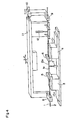
- Fig. 4 shows a perspective view of a fiber type coupler manufacturing apparatus.
- the optical fiber wires 1 and 2 are gripped by first clamp members 5 and 6 which are fixed on fine movement stages 3 and 4 which are finely movable along the optical axis.
- a heating device 7 such as a burner is arranged below the portions from which the coatings have been removed.
- Second clamp members 8 and 9 are arranged on the both sides of the clamp members 5 and 6 along the optical axis of the optical fiber wires 1 and 2.
- the second clamp members 8 and 9 are mounted on a 3-way movable stage 11 which is movable in three directions (optical axis direction and two directions which are orthogonal to the optical axis) through a tension application mechanism 10.
- the tension application mechanism 10 includes a micrometer so that it can drive the second clamp member 9 by a unit of micron.
- a tension measurement device 12 is arranged between the first clamp member 6 and the second clamp member 9 to measure the tension applied to the optical fiber.
- a step 201 the coatings of the optical fiber wires 1 and 2 are partially removed, and the optical fibers 1a and 2a having the coatings thus removed are contacted to each other (see Fig. 3A) and gripped by the first clamp member 5, 6.
- the optical fibers 1a and 2a may be twisted each other.
- a step 202 the contact area is fused by a heating device 3 such as a burner and it is extended by the first clamp members 5 and 6 along the optical axis. (see Fig. 3B and 4).
- a light split ratio is detected in the step of fusion and extension by measuring the light applied to one end of the optical fiber, at the other end.
- a step 204 when a predetermined light split ratio is obtained, the fusion and extension (heating) of the optical fiber are stopped, and a coupler member having a coupler A is formed (see Fig. 3C). After the coupler member has been formed, the first clamp members 5 and 6 are released and the optical fiber wires 1 and 2 are gripped by the second clamp members 8 and 9.
- a step 205 the optical fiber wires 1 and 2 are pulled along the optical axis by the second clamp members 8 and 9, and the coupler member A is fixed to the protective member 13 while the tension is applied to the optical fibers 1a and 2a (see Fig. 3D).
- the second clamp members 8 and 9 are finely driven along the optical axis to apply a predetermined tension to the coupler member (see Fig. 5A).
- the tension applied may be adjusted because the tension is applied while it is monitored by the tension measurement device 12.
- the coupler member is fixed to the protective member 13 such as ceramic by the bonding material such as epoxy resin or ultraviolet ray cured resin (see Fig. 5B).
- the experiment shows a relationship between the tension applied to the fiber type coupler and the break time in the extension process to apply the tension to the fiber type coupler.
- 25 20 and 10 samples were prepared for the tension of 22 grams, 25 grams and 30 grams, respectively.
- An LED light source (wavelength of 1.3 ⁇ m) and a photo-diode are connected to one of the wires to measure a time to the break of the wire. If the wire is broken, the light power from the LED is not propagated and the photo-diode does not detect the light power from the LED.
- the fiber type coupler used in the experiment has the split ratio of 50% and it can split the transmitted light having the wavelength of 1.3 ⁇ m at 50-50.
- the tension applied should be less than 14 grams. However, if the tension is too low, it is not possible to fix the coupler to the protective material without degrading the characteristic of the split ratio. Accordingly, it is desirable that the applied tension is set between 4 grams and 14 grams.
- the split ratio is not limited to 50%, and the present invention is applicable not only to the single wavelength light propagation fiber type coupler but also the multi-wavelength one.
- a tapered optical fiber wire may be used as the optical fiber wire of the coupler member.
- Fig. 7 shows a flow chart of the manufacturing process for the fiber type coupler in accordance with the other embodiment of the present invention
- Fig. 8A to 8E show a process chart of the method for the manufacturing the fiber type coupler.
- a step 301 the coatings of the optical fiber wires 1 and 2 are partially removed, and the optical fibers 1a and 2a are contacted to each other (see Fig. 8A).
- a heating device 7 such as a burner and it is extended along the optical axis. (see Fig. 8B).
- a light split ratio is detected in the step of fusion and extension by measurement of the light applied to one end of the optical fiber, at the other end.
- a step 304 when a predetermined light split ratio is obtained, the fusion and extension of the optical fiber are stopped, and a coupler member having a coupler A is formed (see Fig. 8C).
- a predetermined tension is applied to the coupler member along the optical axis to check any break in the coupler member (see Fig. 8D).
- a step 306 only the coupler member which has not been broken in the test is fixed to the protective material 4 by the bonding material such as epoxy resin or ultraviolet ray cured resin, to form the fiber type coupler (see Fig. 8E).
- the fiber type coupler is extended until the predetermined split ratio is reached in the extension step. Then, it is cooled to a room temperature and pulled along the optical axis to apply the tension to the coupler A (having the diameter of approximately 20 ⁇ m). In this manner, a probability of break is examined for 70 fiber type couplers. In this case, a distance L between the fiber grip members was 25mm, and the displacements ⁇ L were 50 ⁇ m, 100 ⁇ m and 150 ⁇ m, and the tension was applied for ten seconds.
- the heat cycle test shown in Fig. 9B was done 20 times for the fiber type couplers whose break probability had been examined.
- the manufactured fiber type coupler is left at 20 °C for one hour, heated to 100 °C in one hour, left at 100 °C for one hour, cooled to -40 °C in one hour, left at -40 °C for one hour and heated to 20 °C in one hour to complete the cycle.
- Fig. 9A the result of the heat cycle test is shown by a broken line. It is seen from the result of experiment that the fiber type coupler whose displacement ⁇ L is longer than 100 ⁇ m shows a particularly low break probability (almost 0%). It is considered that this is because the fiber type couplers having low break strength have been removed in the experiment applying increased displacement ⁇ L.
- the fiber type coupler used in the experiment has the split ratio of 50% which splits the transmitted light having the wavelength of 1.3 ⁇ m at 50-50.
- the excess loss is less than 0.1 dB, and the protective material (mold case) is made of ceramic (MgO3).
- the stage for fixing the fiber grip member to extend the fiber type coupler along the optical axis is controlled by a pulse motor and a computer, and the extension and the application of the tension are accurately controlled in the order of micron.
Landscapes
- Physics & Mathematics (AREA)
- General Physics & Mathematics (AREA)
- Optics & Photonics (AREA)
- Engineering & Computer Science (AREA)
- Plasma & Fusion (AREA)
- Mechanical Coupling Of Light Guides (AREA)
- Light Guides In General And Applications Therefor (AREA)
Abstract
Description
- The present invention relates to a method for manufacturing a fiber type coupler for splitting or merging a propagated light in an optical fiber, and more particularly to a method for manufacturing the fiber type coupler including a step of fusing and extending a plurality of optical fibers.
- The fiber type coupler has a function to split and couple single wavelength lights or split and merge multi-wavelength lights. The manufacturing method thereof includes a fuse extension method in which fibers are fused and extended, and a grind method in which two optical fibers having sides thereof ground are faced each other.
- Fig. 1 is a flow chart which shows a related background art of fiber type coupler manufacturing method (fuse and extend method). (Electronics Letters, 15th March 1984, Vol. 20, No. 6, PP. 230 - 232) A fiber type coupler which uses a single mode fiber is now explained.
- Coatings of two optical fibers are partially removed and the optical fibers are contacted to each other (step 101). Then, the contacted areas are fused parallelly by heating them with a burner and then the optical fibers are extended along the optical axis (step 102). In this case, a light applied to one end of the optical fiber is measured at the other end to detect a light split ratio (step 103). If a predetermined split ratio is obtained, the extension of the optical fiber is stopped and a coupler member is formed (step 104). Then, the coupler member is fixed and bonded to a protective member to form the fiber type coupler (step 105).
- In other related background art method, two optical fibers are not fused and extended but twisted a heated and extended ("a Discussion on A Manufacturing Method of A Biconical Tapered Distributor", 1984 National Conference of Light-Electromagnetic Wave Section of the Institute of Electronics and Communication Engineers of Japan)
- The related background art fiber type coupler is fixed to the protective material by the bonding material. The coupler whose diameter has been reduced by the extension has a diameter of less than 20µm which is almost one tenth of the diameter before the extension.
- As a result, the tensile strength at the coupler is remarkably reduced, and it may be broken in the heat cycle.
- Thus, the related background art fiber type coupler exhibits a low reliability is an environment where the heat cycle is applied.
- It is, therefore, an object of the present invention to provide a method for manufacturing a fiber type coupler which is hardly broken in the environment of varying temperature so that the long term reliability of the fiber type coupler is improved.
- In order to achieve the above object, the method for manufacturing the fiber type coupler by extending at least two optical fibers, along an optical axis while fusing the optical fibers to form a coupler member, is characterized by a step of adding a tension to the coupler member along the optical axis before the coupler member is fixed to a protective member.
- The present invention will become more fully understood from the detailed description given hereinbelow and the accompanying drawings which are given by way of illustration only, and thus are not to be considered as limiting the present invention.
- Further scope of applicability of the present invention will become apparent from the detailed description given hereinafter. However, it should be understood that the detailed description and specific examples, while indicating preferred embodiments of the invention, are given by way of illustration only, since various changes and modifications within the spirit and scope of the invention will become apparent to those skilled in the art from this detailed description.
-
- Fig. 1 shows a manufacturing method for a fiber type coupler in accordance with the related background art.
- Fig. 2 shows a flow chart of a manufacturing method for a fiber type coupler in accordance with one embodiment of the present invention,
- Figs. 3A to 3D show a process chart of a manufacturing process of the fiber type coupler,
- Fig. 4 shows a perspective view of a manufacturing apparatus for the fiber type coupler,
- Figs. 5A and 5B show a process chart for fixing the coupler member,
- Fig. 6 shows a result of experiment relating to a relationship between an applied tension and a break time,
- Fig. 7 shows a flow chart of a manufacturing method of a fiber type coupler in accordance with one embodiment of the present invention,
- Fig. 8A to 8E show a process chart of a manufacturing process of the fiber type coupler, and
- Fig. 9A and 9B show a result of experiment for the present invention.
- Fig. 2 shows a flow chart of the manufacturing process for the fiber type coupler in accordance with the embodiment of the present invention, Figs. 3A to 3D show a process chart of the method for manufacturing the fiber type coupler, and Fig. 4 shows a perspective view of a fiber type coupler manufacturing apparatus.
- The
optical fiber wires 1 and 2 are gripped byfirst clamp members fine movement stages heating device 7 such as a burner is arranged below the portions from which the coatings have been removed.Second clamp members clamp members optical fiber wires 1 and 2. Thesecond clamp members tension application mechanism 10. Thetension application mechanism 10 includes a micrometer so that it can drive thesecond clamp member 9 by a unit of micron. Atension measurement device 12 is arranged between thefirst clamp member 6 and thesecond clamp member 9 to measure the tension applied to the optical fiber. - The method for manufacturing the fiber type coupler is now explained with reference to Fig. 2.
- In a
step 201, the coatings of theoptical fiber wires 1 and 2 are partially removed, and theoptical fibers 1a and 2a having the coatings thus removed are contacted to each other (see Fig. 3A) and gripped by thefirst clamp member optical fibers 1a and 2a may be twisted each other. - In a
step 202, the contact area is fused by aheating device 3 such as a burner and it is extended by thefirst clamp members - In a
step 203, a light split ratio is detected in the step of fusion and extension by measuring the light applied to one end of the optical fiber, at the other end. - In a
step 204, when a predetermined light split ratio is obtained, the fusion and extension (heating) of the optical fiber are stopped, and a coupler member having a coupler A is formed (see Fig. 3C). After the coupler member has been formed, thefirst clamp members optical fiber wires 1 and 2 are gripped by thesecond clamp members - In a
step 205, theoptical fiber wires 1 and 2 are pulled along the optical axis by thesecond clamp members protective member 13 while the tension is applied to theoptical fibers 1a and 2a (see Fig. 3D). - A method for fixing the coupler member is now explained with reference to Figs. 5A and 5B. The
second clamp members tension measurement device 12. - Then, with the tension being applied, the coupler member is fixed to the
protective member 13 such as ceramic by the bonding material such as epoxy resin or ultraviolet ray cured resin (see Fig. 5B). - Referring now to Fig. 6, a result of experiment for the fiber type coupler of the present embodiment is explained. The experiment shows a relationship between the tension applied to the fiber type coupler and the break time in the extension process to apply the tension to the fiber type coupler. In the experiment, 25, 20 and 10 samples were prepared for the tension of 22 grams, 25 grams and 30 grams, respectively. An LED light source (wavelength of 1.3µm) and a photo-diode are connected to one of the wires to measure a time to the break of the wire. If the wire is broken, the light power from the LED is not propagated and the photo-diode does not detect the light power from the LED. The fiber type coupler used in the experiment has the split ratio of 50% and it can split the transmitted light having the wavelength of 1.3µm at 50-50.
- According to the experiment, in order to assure non-break for 20 years, the tension applied should be less than 14 grams. However, if the tension is too low, it is not possible to fix the coupler to the protective material without degrading the characteristic of the split ratio. Accordingly, it is desirable that the applied tension is set between 4 grams and 14 grams.
- The present invention is not limited to the above embodiment. For example, the split ratio is not limited to 50%, and the present invention is applicable not only to the single wavelength light propagation fiber type coupler but also the multi-wavelength one.
- A tapered optical fiber wire may be used as the optical fiber wire of the coupler member.
- Fig. 7 shows a flow chart of the manufacturing process for the fiber type coupler in accordance with the other embodiment of the present invention, and Fig. 8A to 8E show a process chart of the method for the manufacturing the fiber type coupler.
- In a
step 301, the coatings of theoptical fiber wires 1 and 2 are partially removed, and theoptical fibers 1a and 2a are contacted to each other (see Fig. 8A). - In a
step 302, the contact area is fused by aheating device 7 such as a burner and it is extended along the optical axis. (see Fig. 8B). - In a
step 303, a light split ratio is detected in the step of fusion and extension by measurement of the light applied to one end of the optical fiber, at the other end. - In a
step 304, when a predetermined light split ratio is obtained, the fusion and extension of the optical fiber are stopped, and a coupler member having a coupler A is formed (see Fig. 8C). - In a
step 305, a predetermined tension is applied to the coupler member along the optical axis to check any break in the coupler member (see Fig. 8D). - In a
step 306, only the coupler member which has not been broken in the test is fixed to theprotective material 4 by the bonding material such as epoxy resin or ultraviolet ray cured resin, to form the fiber type coupler (see Fig. 8E). - Referring now to Figs. 9A and 9B, a result of experiment for the fiber type coupler of the present embodiment is explained. In the experiment, the fiber type coupler is extended until the predetermined split ratio is reached in the extension step. Then, it is cooled to a room temperature and pulled along the optical axis to apply the tension to the coupler A (having the diameter of approximately 20 µm). In this manner, a probability of break is examined for 70 fiber type couplers. In this case, a distance L between the fiber grip members was 25mm, and the displacements ΔL were 50µm, 100µm and 150µm, and the tension was applied for ten seconds.
- In Fig. 3, the break probability for the newly manufactured fiber type couplers is shown by a solid line. Accordingly to the experiment, the break probability rapidly increases as the displacement ΔL increases.
- Then, the heat cycle test shown in Fig. 9B was done 20 times for the fiber type couplers whose break probability had been examined. In the heat cycle test, the manufactured fiber type coupler is left at 20 °C for one hour, heated to 100 °C in one hour, left at 100 °C for one hour, cooled to -40 °C in one hour, left at -40 °C for one hour and heated to 20 °C in one hour to complete the cycle.
- In Fig. 9A, the result of the heat cycle test is shown by a broken line. It is seen from the result of experiment that the fiber type coupler whose displacement ΔL is longer than 100µm shows a particularly low break probability (almost 0%). It is considered that this is because the fiber type couplers having low break strength have been removed in the experiment applying increased displacement ΔL.
- In general, it is effective to pull the coupler by the displacement which is longer than five times of the outer diameter of the coupler at the velocity of 10µm(half of the diameter)/sec.
- The fiber type coupler used in the experiment has the split ratio of 50% which splits the transmitted light having the wavelength of 1.3µm at 50-50.
- The excess loss is less than 0.1 dB, and the protective material (mold case) is made of ceramic (MgO₃).
- The stage for fixing the fiber grip member to extend the fiber type coupler along the optical axis is controlled by a pulse motor and a computer, and the extension and the application of the tension are accurately controlled in the order of micron.
- From the invention thus described, it will be obvious that the invention may be varied in many ways. Such variations are not to be regarded as a departure from the spirit and scope of the invention, and all such modifications as would be obvious to one skilled in the art are intended to be included within the scope of the following claims.
Claims (13)
characterized by a step of adding a tension to the coupler member along the optical axis before the coupler member is fixed to a protective member.
characterized by a first step of forming a coupler member by fusing at least two coating-removed optical fibers to extend along an optical axis, and
a second step of fixing the coupler member to a protective member while a predetermined tension is applied to the coupler member along the optical axis.
characterized by a first step of forming a coupler member by fusing at least two coating-removed optical fibers to extend along an optical axis,
a second step of checking any break in said coupler member by applying a predetermined tension to said coupler member along the optical axis, and
a third step of fixing a break-free coupler member to a protective member to form the fiber type coupler.
fiber grip means for gripping said at least two fibers at the both ends along the optical axis;
fiber heating means arranged between said fiber grip means for heating said at least two optical fibers;
tension application means for applying a tension to said at least two optical fibers heated by said fiber heating means, along the optical axis; and
tension measurement means for measuring the tension applied by said tension application means.
a first step of fusing at least two optical fibers and extending said at least two fused optical fibers along an optical axis to form a coupler member.
Applications Claiming Priority (4)
| Application Number | Priority Date | Filing Date | Title |
|---|---|---|---|
| JP269105/88 | 1988-10-25 | ||
| JP26910588A JPH02114213A (en) | 1988-10-25 | 1988-10-25 | Manufacturing method of fiber coupler |
| JP270009/88 | 1988-10-26 | ||
| JP63270009A JPH0666005B2 (en) | 1988-10-26 | 1988-10-26 | Fiber-type turnip manufacturing method |
Publications (3)
| Publication Number | Publication Date |
|---|---|
| EP0366110A2 true EP0366110A2 (en) | 1990-05-02 |
| EP0366110A3 EP0366110A3 (en) | 1991-07-17 |
| EP0366110B1 EP0366110B1 (en) | 1995-06-28 |
Family
ID=26548618
Family Applications (1)
| Application Number | Title | Priority Date | Filing Date |
|---|---|---|---|
| EP89119834A Expired - Lifetime EP0366110B1 (en) | 1988-10-25 | 1989-10-25 | Method for manufacturing a fiber type coupler |
Country Status (4)
| Country | Link |
|---|---|
| US (1) | US5013117A (en) |
| EP (1) | EP0366110B1 (en) |
| AU (1) | AU617547B2 (en) |
| DE (1) | DE68923244T2 (en) |
Cited By (7)
| Publication number | Priority date | Publication date | Assignee | Title |
|---|---|---|---|---|
| EP0397383A1 (en) * | 1989-05-09 | 1990-11-14 | Fujikura Ltd. | Optical fiber coupler manufacturing device |
| EP0559174A1 (en) * | 1992-03-04 | 1993-09-08 | Sumitomo Electric Industries, Ltd | Optical fiber coupler and its manufacturing method |
| EP0578980A1 (en) * | 1992-07-16 | 1994-01-19 | Corning Incorporated | Environmentally robust fiber optic coupler and method |
| AU657023B2 (en) * | 1992-02-01 | 1995-02-23 | Alcatel N.V. | Optical connection arrangement |
| EP0710859A1 (en) * | 1994-10-25 | 1996-05-08 | Sumitomo Electric Industries, Ltd. | Method for producing optical fiber coupler |
| CN1037374C (en) * | 1991-07-02 | 1998-02-11 | 住友电气工业株式会社 | Fiber optic coupler manufacturing facility with automatic pull-off test equipment |
| US6976796B2 (en) | 2002-05-17 | 2005-12-20 | Sumitomo Electric Industries, Ltd. | Method and jig for handling and transferring fusion-spliced optical fibers |
Families Citing this family (14)
| Publication number | Priority date | Publication date | Assignee | Title |
|---|---|---|---|---|
| US5170450A (en) * | 1991-04-03 | 1992-12-08 | The Charles Stark Draper Laboratory, Inc. | Dual-core fiber launching coupler |
| US5268014A (en) * | 1992-11-05 | 1993-12-07 | Corning Incorporated | Method of making robust fiber optic coupler |
| US5680495A (en) * | 1996-07-12 | 1997-10-21 | Bloom; Cary | Fiber optic device sealed by compressed metal seals and method for making the same |
| US5815619A (en) * | 1996-12-10 | 1998-09-29 | Bloom; Cary | Fiber optic connector hermetically terminated |
| US5971629A (en) * | 1996-07-12 | 1999-10-26 | Bloom; Cary | Apparatus and method bonding optical fiber and/or device to external element using compliant material interface |
| US6000858A (en) * | 1996-07-12 | 1999-12-14 | Bloom; Cary | Apparatus for, and method of, forming a low stress tight fit of an optical fiber to an external element |
| US5805757A (en) * | 1996-12-10 | 1998-09-08 | Bloom; Cary | Apparatus and method for preserving optical characteristics of a fiber optic device |
| US5871559A (en) * | 1996-12-10 | 1999-02-16 | Bloom; Cary | Arrangement for automated fabrication of fiber optic devices |
| US5931983A (en) * | 1996-09-24 | 1999-08-03 | Bloom; Cary | Method of forming a fiber optic coupler by dynamically adjusting pulling speed |
| US6177985B1 (en) | 1996-10-01 | 2001-01-23 | Cary Bloom | Apparatus and method for testing optical fiber system components |
| US5764348A (en) * | 1996-10-01 | 1998-06-09 | Bloom; Cary | Optical switching assembly for testing fiber optic devices |
| US6074101A (en) * | 1996-12-10 | 2000-06-13 | Bloom; Cary | Apparatus for, and method of, forming a low stress tight fit of an optical fiber to an external element |
| US5917975A (en) * | 1996-12-10 | 1999-06-29 | Bloom; Cary | Apparatus for, and method of, forming a low stress tight fit of an optical fiber to an external element |
| US6003341A (en) | 1996-12-10 | 1999-12-21 | Bloom; Cary | Device for making fiber couplers automatically |
Family Cites Families (9)
| Publication number | Priority date | Publication date | Assignee | Title |
|---|---|---|---|---|
| DE2812346A1 (en) * | 1977-03-23 | 1978-09-28 | Tokyo Shibaura Electric Co | LIGHT DISTRIBUTOR |
| US4291940A (en) * | 1977-06-13 | 1981-09-29 | Canadian Patents & Development Ltd. | Low loss access coupler for multimode optical fiber distribution systems |
| JPS5595918A (en) * | 1979-01-11 | 1980-07-21 | Sumitomo Electric Ind Ltd | Automatic connector of optical fiber |
| US4377403A (en) * | 1980-09-29 | 1983-03-22 | The United States Of America As Represented By The Secretary Of The Navy | Method of fabricating a fused single-mode fiber bidirectional coupler |
| AU569803B2 (en) * | 1984-09-06 | 1988-02-18 | Hitachi Limited | Optical fibre star coupler |
| EP0234325A3 (en) * | 1986-02-24 | 1988-01-07 | Allied Corporation | Multimode optical fiber coupler and method of manufacture thereof |
| GB2190762B (en) * | 1986-05-23 | 1989-12-13 | Stc Plc | Directional coupler |
| US4957338A (en) * | 1986-11-14 | 1990-09-18 | The Commonwealth Of Australia | Fabrication of fibre optic components |
| US4869570A (en) * | 1987-02-21 | 1989-09-26 | Nippon Telegraph And Telephone Corporation | Fiber coupler and method and apparatus for manufacturing the same |
-
1989
- 1989-10-13 US US07/421,098 patent/US5013117A/en not_active Expired - Lifetime
- 1989-10-20 AU AU43530/89A patent/AU617547B2/en not_active Expired
- 1989-10-25 EP EP89119834A patent/EP0366110B1/en not_active Expired - Lifetime
- 1989-10-25 DE DE68923244T patent/DE68923244T2/en not_active Expired - Lifetime
Cited By (11)
| Publication number | Priority date | Publication date | Assignee | Title |
|---|---|---|---|---|
| EP0397383A1 (en) * | 1989-05-09 | 1990-11-14 | Fujikura Ltd. | Optical fiber coupler manufacturing device |
| US5030265A (en) * | 1989-05-09 | 1991-07-09 | Fujikura Ltd. | Optical fiber coupler manufacturing device |
| CN1037374C (en) * | 1991-07-02 | 1998-02-11 | 住友电气工业株式会社 | Fiber optic coupler manufacturing facility with automatic pull-off test equipment |
| AU657023B2 (en) * | 1992-02-01 | 1995-02-23 | Alcatel N.V. | Optical connection arrangement |
| EP0559174A1 (en) * | 1992-03-04 | 1993-09-08 | Sumitomo Electric Industries, Ltd | Optical fiber coupler and its manufacturing method |
| US5325450A (en) * | 1992-03-04 | 1994-06-28 | Sumitomo Electric Industries, Ltd. | Optical fiber coupler and its manufacturing method |
| CN1036805C (en) * | 1992-03-04 | 1997-12-24 | 住友电器工业株式会社 | Optical fiber coupler and its manufacturing method |
| EP0578980A1 (en) * | 1992-07-16 | 1994-01-19 | Corning Incorporated | Environmentally robust fiber optic coupler and method |
| US5405474A (en) * | 1992-07-16 | 1995-04-11 | Corning Incorporated | Environmentally robust fiber optic coupler and method |
| EP0710859A1 (en) * | 1994-10-25 | 1996-05-08 | Sumitomo Electric Industries, Ltd. | Method for producing optical fiber coupler |
| US6976796B2 (en) | 2002-05-17 | 2005-12-20 | Sumitomo Electric Industries, Ltd. | Method and jig for handling and transferring fusion-spliced optical fibers |
Also Published As
| Publication number | Publication date |
|---|---|
| EP0366110B1 (en) | 1995-06-28 |
| EP0366110A3 (en) | 1991-07-17 |
| US5013117A (en) | 1991-05-07 |
| AU617547B2 (en) | 1991-11-28 |
| DE68923244D1 (en) | 1995-08-03 |
| DE68923244T2 (en) | 1996-01-04 |
| AU4353089A (en) | 1990-05-03 |
Similar Documents
| Publication | Publication Date | Title |
|---|---|---|
| US5013117A (en) | Method for manufacturing a fiber type coupler | |
| US4634217A (en) | High tensile wire provided with light guide sensor | |
| KR900008598B1 (en) | Fiber optic birefringent data bus tap | |
| US4618212A (en) | Optical fiber splicing using leaky mode detector | |
| JPH08286074A (en) | Apparatus and method for aligning an optical fiber array with an optical integrated circuit assembly | |
| JPH0439044B2 (en) | ||
| EP0978739B1 (en) | Optical fiber splice protector and method for applying same | |
| JPS6247604A (en) | Terminal part for multicore fiber | |
| JPS61502222A (en) | Optical fiber splices and how to make them | |
| US6385372B1 (en) | Fiber optical coupler fabrication and system | |
| GB2145516A (en) | Crack or strain monitors | |
| JP2915196B2 (en) | Optical fiber material and its manufacturing method | |
| GB2185127A (en) | Fusion splicing optical fibres | |
| JPH0449084B2 (en) | ||
| JP3161866B2 (en) | Manufacturing method of optical fiber coupler | |
| JPH02181708A (en) | Two core type temperature detecting optical fiber | |
| JPH0666005B2 (en) | Fiber-type turnip manufacturing method | |
| JPH02103434A (en) | Method for measuring strain distribution in longitudinal direction of optical fiber cable and apparatus and optical fiber used in said method | |
| US6718096B2 (en) | Compact and multiple optical fiber coupler and method of making the same | |
| JP2942270B2 (en) | Water immersion sensor and water immersion detection method | |
| JPH08334651A (en) | Multi-fiber optical connector | |
| JPS612110A (en) | Multicored strand of optical fiber | |
| JPH0334722Y2 (en) | ||
| KR930004973B1 (en) | Optical Fiber Splices and Manufacturing Method Thereof | |
| JP3140114B2 (en) | Optical fixed attenuator |
Legal Events
| Date | Code | Title | Description |
|---|---|---|---|
| PUAI | Public reference made under article 153(3) epc to a published international application that has entered the european phase |
Free format text: ORIGINAL CODE: 0009012 |
|
| AK | Designated contracting states |
Kind code of ref document: A2 Designated state(s): DE FR GB IT SE |
|
| 17P | Request for examination filed |
Effective date: 19901220 |
|
| PUAL | Search report despatched |
Free format text: ORIGINAL CODE: 0009013 |
|
| AK | Designated contracting states |
Kind code of ref document: A3 Designated state(s): DE FR GB IT SE |
|
| 17Q | First examination report despatched |
Effective date: 19930503 |
|
| GRAA | (expected) grant |
Free format text: ORIGINAL CODE: 0009210 |
|
| AK | Designated contracting states |
Kind code of ref document: B1 Designated state(s): DE FR GB IT SE |
|
| ET | Fr: translation filed | ||
| REF | Corresponds to: |
Ref document number: 68923244 Country of ref document: DE Date of ref document: 19950803 |
|
| ITF | It: translation for a ep patent filed | ||
| PLBE | No opposition filed within time limit |
Free format text: ORIGINAL CODE: 0009261 |
|
| STAA | Information on the status of an ep patent application or granted ep patent |
Free format text: STATUS: NO OPPOSITION FILED WITHIN TIME LIMIT |
|
| 26N | No opposition filed | ||
| REG | Reference to a national code |
Ref country code: GB Ref legal event code: 746 Effective date: 19980331 |
|
| REG | Reference to a national code |
Ref country code: FR Ref legal event code: D6 |
|
| REG | Reference to a national code |
Ref country code: GB Ref legal event code: IF02 |
|
| PGFP | Annual fee paid to national office [announced via postgrant information from national office to epo] |
Ref country code: SE Payment date: 20051005 Year of fee payment: 17 |
|
| PG25 | Lapsed in a contracting state [announced via postgrant information from national office to epo] |
Ref country code: SE Free format text: LAPSE BECAUSE OF NON-PAYMENT OF DUE FEES Effective date: 20061026 |
|
| EUG | Se: european patent has lapsed | ||
| PGFP | Annual fee paid to national office [announced via postgrant information from national office to epo] |
Ref country code: DE Payment date: 20081027 Year of fee payment: 20 |
|
| PGFP | Annual fee paid to national office [announced via postgrant information from national office to epo] |
Ref country code: IT Payment date: 20081025 Year of fee payment: 20 |
|
| PGFP | Annual fee paid to national office [announced via postgrant information from national office to epo] |
Ref country code: FR Payment date: 20081014 Year of fee payment: 20 |
|
| PGFP | Annual fee paid to national office [announced via postgrant information from national office to epo] |
Ref country code: GB Payment date: 20081022 Year of fee payment: 20 |
|
| REG | Reference to a national code |
Ref country code: GB Ref legal event code: PE20 Expiry date: 20091024 |
|
| PG25 | Lapsed in a contracting state [announced via postgrant information from national office to epo] |
Ref country code: GB Free format text: LAPSE BECAUSE OF EXPIRATION OF PROTECTION Effective date: 20091024 |