EP0366112A2 - Optische Koordinateneingabevorrichtung und Positionszeiger dafür - Google Patents
Optische Koordinateneingabevorrichtung und Positionszeiger dafür Download PDFInfo
- Publication number
- EP0366112A2 EP0366112A2 EP89119838A EP89119838A EP0366112A2 EP 0366112 A2 EP0366112 A2 EP 0366112A2 EP 89119838 A EP89119838 A EP 89119838A EP 89119838 A EP89119838 A EP 89119838A EP 0366112 A2 EP0366112 A2 EP 0366112A2
- Authority
- EP
- European Patent Office
- Prior art keywords
- coordinate
- mirror
- position indicator
- plane
- optical
- Prior art date
- Legal status (The legal status is an assumption and is not a legal conclusion. Google has not performed a legal analysis and makes no representation as to the accuracy of the status listed.)
- Granted
Links
Images







Classifications
-
- G—PHYSICS
- G06—COMPUTING OR CALCULATING; COUNTING
- G06F—ELECTRIC DIGITAL DATA PROCESSING
- G06F3/00—Input arrangements for transferring data to be processed into a form capable of being handled by the computer; Output arrangements for transferring data from processing unit to output unit, e.g. interface arrangements
- G06F3/01—Input arrangements or combined input and output arrangements for interaction between user and computer
- G06F3/03—Arrangements for converting the position or the displacement of a member into a coded form
- G06F3/041—Digitisers, e.g. for touch screens or touch pads, characterised by the transducing means
- G06F3/042—Digitisers, e.g. for touch screens or touch pads, characterised by the transducing means by opto-electronic means
- G06F3/0421—Digitisers, e.g. for touch screens or touch pads, characterised by the transducing means by opto-electronic means by interrupting or reflecting a light beam, e.g. optical touch-screen
- G06F3/0423—Digitisers, e.g. for touch screens or touch pads, characterised by the transducing means by opto-electronic means by interrupting or reflecting a light beam, e.g. optical touch-screen using sweeping light beams, e.g. using rotating or vibrating mirror
-
- G—PHYSICS
- G01—MEASURING; TESTING
- G01S—RADIO DIRECTION-FINDING; RADIO NAVIGATION; DETERMINING DISTANCE OR VELOCITY BY USE OF RADIO WAVES; LOCATING OR PRESENCE-DETECTING BY USE OF THE REFLECTION OR RERADIATION OF RADIO WAVES; ANALOGOUS ARRANGEMENTS USING OTHER WAVES
- G01S5/00—Position-fixing by co-ordinating two or more direction or position line determinations; Position-fixing by co-ordinating two or more distance determinations
- G01S5/16—Position-fixing by co-ordinating two or more direction or position line determinations; Position-fixing by co-ordinating two or more distance determinations using electromagnetic waves other than radio waves
Definitions
- the present invention relates to an optical coordinate input apparatus and a position indicator thereof capable of inputting information about manuscripts, figures, precise drawings, and the like to a host apparatus. More particularly, the present invention relates to an optical coordinate input apparatus and a position indicator thereof which can be optionally applied to a subject two-dimensional coordinate plane and in which a region to which coordinate input is indicated is substantially freed from restrictions.
- coordinate input apparatuses capable of inputting two dimensional coordinates
- the apparatuses being for example of an electrostrictive type, an electromagnetic induction type, a pressure sensitive type, an electrostatic induction type, or the like. All of these apparatuses are basically arranged so as to have a coordinate indicating portion constituted by combining a tablet (or a keyboard) defining a two dimensional coordinate plane and a movable position indicating apparatus.
- the tablet and the position indicating apparatus communicate with each other by means of an electric, magnetic, or mechanical signal so that the position on the two-dimensional coordinate plane of the position indicating apparatus is detected.
- the input coordinates are indicated.
- the above-described conventional coordinate input apparatus is constituted such that the tablet thereof is arranged to be an exclusive tablet of a special structure having predetermined dimensions, shape, and structure in accordance with the physical quantity to be used for the purpose of enabling the signal transmission/receipt to and from the position indicating apparatus. Therefore, there has been a paper size limit from the viewpoint of the manufacturing technology, the largest paper size being about A0 size even if the electromagnet type apparatus, which is considered to be advantageous in accuracy and to be thereby suitable to larger sizes, is used. Furthermore, the plane region to which input of the coordinates can be provided has been necessarily limited by the area of the tablet. Therefore, input of graphics drawn over an optional area cannot be freely provided regardless of whether the area is wide or narrow.
- the position indicator of the above-described conventional coordinate input apparatus has been always used in combination with a special tablet capable of transmitting and receiving a signal. Therefore, the conventional coordinate input apparatus cannot solely, that is, in a manner separated from the tablet, be applied to an optional two dimensional coordinate plane. Furthermore, since the dimensions of the plane of the exclusive tablet have been physically limited, the position indicator cannot be used for freely inputting two dimensional information in a wide range.
- a first object of the present invention is to provide a coordinate input apparatus freed from the conventional restriction of the tablet and thereby capable of being applied to a wide two dimensional coordinate plane.
- an optical coordinate input apparatus comprises: a reflection type position indicator capable of designating a coordinate to be input and movably disposed over a two dimensional coordinate plane having a given size so that incident light passing along an optical path which is directed toward a central axis of the position indicator is reflected, the reflected light being then passed reversely along the optical path; a light source portion disposed on the coordinate plane so as to emit incident light with angularly scanning the coordinate plane from two points disposed away from each other on a reference line and capable of receiving light which is passing reversely after it has been reflected by the position indicator when the incident light coincides with the optical path and a calculating portion capable of calculating angles between the optical paths connecting the two points to the central axis of the position indicator and the reference line and further calculating the coordinate designated by the position indicator by using the thus calculated angles and the distance between the two points in accordance with a principle of triangulation.
- the reflection type position indicator is disposed on the two dimensional coordinate plane in order to designate the coordinate to be inputted.
- the light source portion disposed on this coordinate plane emits light beams from two points which are positioned away from each other on the reference line toward the reflection type position indicator, and the coordinate plane is angularly scanned simultaneously by said light beams.
- the incident light beam passing along the optical path toward the central axis of the position indicator is reflected by this position indicator, causing the reflected light beam to propagate in the reverse direction.
- the light source portion receives the light beam propagating in the reverse direction, it transmits an output signal.
- the arithmetic portion calculates the angles between the reference line and the optical paths connecting the above described two points and the central axis of the position indicator.
- the arithmetic portion uses the thus obtained angles and the distance between the two points so as to calculate the coorinates designated by the position indicator in accordance with the principl eof triangulation.
- the coordinate input apparatus is arranged to be operated on the basis of the incident and emitted light beam between the reflection type position indicator and the light source portion which are respectively positioned so as to hold a predetermined relative positional relationship with respect to the two dimensional coordinate plane. Therefore, it is not necessary for the coordinate input apparatus to include a tablet having special dimensions and a special construction, as has been necessary in the conventional coordinate input apparatus. Therefore, the apparatus according to the present invention can be freed from the above-described restriction of the tablet, and can thereby be freely applied to any two dimensional coordinate plane. Furthermore, its sensitive input region is free from any restrictions.
- a large size coordinate-input apparatus for example, a coordinate input apparatus having a sensitive input region with a size of several meters square can be easily constituted.
- coordinate information of large sized precise drawings of actual dimensions for example, actual dimensioned precise drawings concerning automobiles or large-sized machines can be precisely and immediately inputted to higher apparatuses as well as the conventional small sized drawings.
- a second object of the present invention is to provide a coordinate input apparatus in which the distance between the two points disposed in the light source portion and positioned away from each other on the reference line can be adjusted in accordance with the area of the coordinate input region.
- an optical coordinate input apparatus is constituted such that the light source portion is mounted on the coordinate plane and includes a pair of light source units capable of emitting light in a manner to angularly scan the coordinate plane from two points disposed away from each other on a reference line and capable of receiving light which is propagating reversely after the light has been reflected by the position indicator when the incident light beams coincide with the straight lines connecting the position indicator with each of said points, the light source position being so arranged that the pair of light source units are movable along the reference line so that the distance between the two points is adjusted so as to correspond to the size of the coordinate plane.
- the pair of light source units in the light source portion are relatively moved to each other along the reference line in accordance with the area of the coordinate input region.
- an extremely excellent optical coordinate input apparatus in terms of various usage can be provided since coordinates can be input to any arbitrarity sized coordinate input regions.
- a third object of the present invention is to provide an optical coordinate input apparatus capable of reducing the intervals between the detections of the coordinates.
- the light source portion emits incident light with angularly scanning along the coordinate plane from two points disposed away from each other on a reference line and receives light which propagates reversely after the light has been reflected by the position indicator when the incident light beams coincide with the straight lines connecting the position indicator with each of said two points, and transmits an output signal.
- the interval between detections of the coordinates can be reduced so that the input of the coordinates can be quickly conducted.
- a fourth object of the present invention is to provide an optical coordinate input apparatus capable of adjusting the calculation timing of the coordinate by a users operation.
- an optical coordinate input apparatus is structured such that the position indicator is provided with a coordinate calculation instruction signal generating circuit capable of generating a signal for commanding a calculation of the coordinates, and the coordinate calculation means is arranged to calculate the coordinate in accordance with an output signal from the coordinate calculation instruction signal generating circuit.
- the timing of the input at the coordinates can be controlled by an operation through the position indicator.
- a fifth object of the present invention is to provide a reflection type position indicator which is freed from the restriction of the tablet in principle and is thereby capable of being freely applied to any two dimensional coordinate planes, the apparatus having a sensitive coordinate input region freed from any substantial restriction.
- the position indicator according to the present invention is structured as to have a mirror portion whose mirror surfaces are formed at positions which are in parallel to a two dimensional coordinate plane, that is, plane XY at the same distance from a central axis and are present on the same plane which is parallel to the plane XY, the position indicator being able to move over the plane XY.
- the position indicator according to the present invention since the position indicator according to the present invention has an optical reflection type structure, the coordinate of the position on the two dimensional coordinate plane designated by the position indicator can be detected in accordance with the principle of triangulation. Therefore, the position indicator according to the present invention can be freed from the tablet so that it can be freely applied to a two dimensional coordinate plane. As a result, any restriction in the coordinate input region can be eliminated.
- a sixth object of the present invention is to provide a position indicator having a function of selectively reflecting an incident light beam passing toward the central axis which represents the position of the position indicator so as to return the reflected light beam to the light source of the incident light.
- the position indicator also has a function in the case where continuous inputs of coordinates are conducted by continuously and manually moving the position indicator (a cursor) on the plane, the function being such that reflected light beam is kept to coincide with the incident light beam even if the position indicator is inclined with respect to the coordinate plane during the movement.
- the position indicator according to the present invention has an annular lens member.
- the annular lens member is made of an optical material in the form of an annular shape having a concentric inner surface and an outer surface, in which the inner surface is formed so as to make the cross sectional shape thereof in parallel to a concentric axis on a cross section cut by a plane including the concentric axis and the outer surface is formed so as to make the cross sectional shape thereof curved outward with a predetermined curvature whereby a lens having its optical axis in the radial direction of the annular shape is achieved, the lens having its focal point on the inner surface.
- a reflection layer is disposed on the inner surface of the annular lens member and capable of reflecting light which has been made incident upon along a plane including the concentric axis and the radial optical axis, the light being reflected in parallel to the incident light.
- the incident light beams passing toward the central axis of the position indicator can be selectively reflected, and the reflected light beam can be returned to the light source of the incident light.
- the position indicator is continuously and manually moved on the plane for conducting a continuously inputting of coordinates, if the position indicator is inclined with respect to the coordinate plane during the movement, the reflected light beam can be kept within the optical paths of incident light beams.
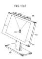
- Fig. 1(a) is a perspective external view which illustrates a first embodiment of the present invention
- Fig. 1(b) is a view which illustrates the arrangement of an optical system for use in the first embodiment.
- reference numeral 100 represents an optical source portion accommodating portion
- 101 represents a light source portion consisting of a pair of light source units 102 and 103.
- Reference numeral 104 represents an input panel
- 105 represents a coordinate input region
- 106 represents a support frame for the input panel 104.
- Reference numeral 110 represents a reflection type position indicator (or a cursor)
- 121 and 122 represent lasers
- 123 and 124 represent half mirrors
- 125 and 126 represent first and second rotary mirrors
- 127 and 128 represent first and second photosensors.
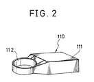
- the position indicator 110 is constituted in such a manner that a cylindrical mirror portion 112 is disposed on one side surface of a box-like main body 111, the bottom portion of the main body 111 and the same of the mirror portion 112 being arranged such that they can be held in parallel to a two dimensional coordinate plane, that is, plane XY.
- a mirror formed on the outer surface of the mirror portion 112 is arranged to be perpendicular to the bottom surface of the mirror portion 112.
- a transparent display plate (omitted from illustration) made of synthetic resin is attached to the above-described bottom surface of the mirror portion 112.
- a hair-cross mark showing the center of the mirror portion 112 is provided on the above-described display plate.
- the coordinate input position can be designated by moving the position indicator 110 over the above-described plane XY.
- Each of the lasers 121 and 122 comprises a semiconductor laser so as to provide a laser beam, which is emitted from the laser 121, made incident upon a rotational axis of a first rotary mirror 125 in parallel to the plane XY via the half mirror 123 disposed on X-axis, the first rotary mirror 125 being disposed at the origin of the XY plane.
- the laser beam emitted from the laser 122 is made incident upon the rotational axis of a second rotary mirror 126 in parallel to the plane XY via the half mirror 124 disposed on X-axis, the second rotary mirror 126 being disposed on the X-axis at a predetermined distance L, for example, 5 m, kept from the first rotary mirror 125.
- Each of the first and second photosensors 127 and 128 comprises an NPN-phototransistor whose collector is connected to a D.C. power source.
- the first photosensor 127 is positioned so as to be capable of detecting, via the half mirror 123, the laser beam which is reflected by the first rotary mirror 125 in the same direction as that of the light beam made incident upon the first rotary mirror 125, the laser beam thus detected being the laser beam emitted from the laser 121.
- the second photosensor 128 is positioned so as to be capable of detecting, via the half mirror 124, the laser beam which is reflected by the second rotary mirror 126 in the same direction as that of the light beam made incident upon the second rotary mirror 126, the laser beam thus detected being the laser beam emitted from the laser 122.
- Specific points P1 and P2 on the respective rotational axes of the rotary mirrors 125 and 126 are positioned on the same reference line which is in parallel to X-axis on the coordinate plane, the specific points P1 and P2 being positioned away from each other.
- the first light source unit 102 is constituted by the laser 121, the half mirror 123, the rotary mirror 125, the photosensor l27, hand a drive portion 131 to be described later.
- the second light source unit 103 is constituted by the laser 122, the half mirror 124, the rotary mirror 126, the photosensor 128, and a drive portion 132.
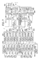
- Fig. 3 is a block diagram which illustrates the electric circuit for use in the first embodiment.
- reference numeral 131 represents a first rotary mirror drive portion capable of rotating the first rotary mirror shown in Fig. 1 counterclockwise at uniform angular velocity ⁇ .
- the first rotary mirror drive portion 131 is also capable of transmitting pulse signal A of logic "1" having a predetermined pulse width T PW when the normal line of the surface of the first rotary mirror 125 agrees with the path at the incident light beam emitted from the laser 121.
- the pulse width T PW of the pulse signal A is arranged to be shorter than time Tf which it takes the first rotary mirror 125 to complete one rotation.
- Reference numeral 132 represents a second rotary mirror drive portion capable of rotating the second rotary mirror 126 shown in Fig. 1 clockwise at uniform angular velocity ⁇ .
- the second rotary mirror drive portion 132 is also capable of transmitting a pulse signal B of logic "1" having a predetermined pulse width T PW when the normal line of the surface of the second rotary mirror 126 agrees with the path of the incident light beam emitted from the laser 122 .
- the pulse width T PW of the pulse signal B is arranged to be shorter than time Tf which it takes the second rotary mirror 126 to complete one rotation.
- Reference numerals 141 and 142 represent level detection circuits which are similar to each other and each of which is constituted by resistors and operation amplifiers.
- the level detection circuit 141 is capable of converting a photoelectric current transmitted from the emitter of the first photosensor 127 into voltage. Furthermore, the level detection circuit 141 causes its output signal to be logic "1" when the thus converted voltage reaches a predetermined reference level.
- the level detection circuit 142 is capable of converting a photoelectric current transmitted from the emitter of the second photosensor 128 into voltage. Furthermore, the level detection circuit 142 causes its output signal to be logic "1" when the thus converted voltage reaches a predetermined reference level.
- Reference numeral 143 represents a clock signal generating circuit capable of transmitting clock signal CK of predetermined period T ck .
- Reference numerals 144 to 147 represent pulse shaping circuits each of which is constituted by a flip-flop and a logical circuit and capable of transmitting a pulse signal having the width of one clock pulse when it detects that the input signal has been changed from logic "0" to logic "1".
- the pulse shaping circuit 144 receives the output signal A from the first rotary mirror drive portion 131 and the clock signal CK and transmits signal C.
- the pulse shaping circuit 145 receives the output signal from the level detection circuit 141 and the clock signal CK and transmits signal E.
- the pulse shaping circuit 146 receives the output signal B from the second rotary mirror drive portion 132 and the clock signal CK and transmits signal D.
- the pulse shaping circuit 147 receives the output signal from the level detection circuit 142 and the clock signal CK and transmits signal F.
- Reference numerals 148 and 149 represent counters each of which counts freely in response to the clock signal CK.
- the counter 148 is arranged to be reset by the pulse signal C transmitted from the pulse shaping circuit 144, while the counter 149 is arranged to be reset by the pulse signal D transmitted from the pulse shaping circuit 146.
- Reference numeral 150 represents an interruption signal generating circuit constituted by a flip-flop and a logical circuit and capable of receiving the output signals E and F from the pulse shaping circuits 145 and 147 and the clock signal CK.
- the interruption signal generating circuit 150 is further capable of transmitting interruption signal INT to a CPU 155 to be described later after it has caused the interruption signal INT to be logic "1" on condition that either the pulse signal E or F is inputted and then the other pulse signal is inputted or condition that both the pulse signals are inputted.
- the interruption signal generating circuit 150 causes the interruption signal INT to be logic "0” under condition that pulse reset signal R of logic "1" is inputted thereto from the CPU 155.
- Reference numerals 151 and 152 represent registers, the input of the register 151 being connected to the output of the counter 148 so as to latch output data from the counter 148 at the front portion of the pulse signal E transmitted from the pulse shaping circuit 145.
- the input of the register 152 is connected to the output of the counter 149 so as to latch output data from the counter 149 at the front portion of the pulse signal F transmitted from the pulse shaping circuit 146.
- Reference numerals 153 and 154 represent tri-state output registers, the input of the register 153 being connected to the output of the register 151 so as to latch output data from the register 151 when the interruption signal INT is changed from logic "0" to logic "1".
- the input of the register 154 is connected to the output of the register 152 so as to latch output data from the register 152 when the interruption signal INT is changed from logic "0" to logic "1".
- Reference numeral 155 represents a CPU connected to the outputs of the registers 153 and 154 via a data bus DB and capable of receiving data registered in the registers 153 and 154 when the interruption signal INT becomes logic "1".
- the CPU 155 is furthermore capable of transmitting pulse reset signal R of logic "1" to output port P1 after inputting data.
- the above-described angle detection means comprises first and second rotary mirror drive portions 131 and 132, the clock signal generating circuit 143, the pulse shaping circuits 144 and 146, and the counters 148 and 149.
- a coordinate arithmetic means that is, a calculating portion comprises the level detection circuits 141 and 142, the clock signal generating circuit 143, the pulse shaping circuits 145 and 147, the interruption signal generating circuit 150, the registers 151 to 154, the CPU 155, and a program, to be described later, capable of operating the CPU 155.
- the reflected light beam is capable of passing from the specific point P1 of the rotary mirror 125 toward the center of the mirror portion 112 of the position indicator 110.
- the laser beam reflected by the mirror portion 112 is made incident upon the first photosensor 127 via the first rotary mirror 125 and the half mirror 123.
- the photoelectric current transmitted from the first photosensor 127 increases so that the output signal from the level detection circuit 141 becomes logic "1".
- the pulse signal E is transmitted from the pulse shaping circuit 145.
- the reflected light beam is capable of passing from the specific point P2 of the rotary mirror 126 toward the center of the mirror portion 112.
- the laser beam reflected by the mirror portion 112 is made incident upon the second photosensor 128 via the second rotary mirror 126 and the half mirror 124.
- the photoelectric current transmitted from the second photosensor 128 increases so that the output signal from the level detection circuit 142 becomes logic "1".
- the pulse signal F is transmitted from the pulse shaping circuit 147.
- Output data from the counter 148 are caused to be latched in the register 151 by the pulse signal E so as to be registered therein as angular data D1 representing the incident angle ⁇ 1 upon the first rotary mirror 125.
- output data from the counter 149 is caused to be latched in the register 152 by the pulse signal F so as to be registered therein as angular data D2 representing the incident angle ⁇ 2 upon the second rotary mirror 126.
- Angular data D1 and D2 are latched in the registers 153 and 154 by the interruption signal INT.
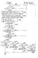
- the CPU 155 always supervises whether or not the interruption signal INT is "1" (in step S1, the term “step” will be omitted hereinafter).
- the interruption signal INT becomes logic "1”
- the CPU 155 receivess the angular data D1 from the register 153 via the data bus (S2) and also receivess the angular data D2 from the register 154 (S3).
- the CPU 155 transmits a signal of logic "1" to the output port P1 for a predetermined time period (S4), and determines whether or not the angular data D1 is 0 (S5). If it is determined that the angular data D1 is 0, the flow returns to S1.
- the CPU 155 determines whether or not the angular data D2 is 0 (S6). If it is determined that the angular data D2 is 0, the flow returns to S1. If it is determined that the angular data D2 is not 0, incident angle ⁇ 1 of the laser beam on the first rotary mirror 125 and incident angle ⁇ 2 on the second rotary mirror 126 are calculated by using the angular data D1 and D2 from the following equations (S7).
- ⁇ 1 2 ⁇ ⁇ Tck ⁇ D1/Tf (radian) (1)
- ⁇ 1 2 ⁇ ⁇ Tck ⁇ D2/Tf (radian) (2)
- Tck represents the period of the clock signal CK
- Tf represents the time it takes the first and second rotary mirrors 125 and 126 to complete one rotation, these factors being previously stored as constants.
- angles ⁇ 1 and ⁇ 2 between the incident light and reflected light on the first and second rotary mirrors 125 and 126 are obtained by doubling the incident angles ⁇ 1 and ⁇ 2 (S8).
- ⁇ 1 2 ⁇ ⁇ 1 (3)
- ⁇ 2 2 ⁇ ⁇ 2 (4)
- X-coordinate and Y-coordinate of the point P0 is obtained by using the following equation (S9).
- x L ⁇ tan ⁇ 2/(tan ⁇ 1 + tan ⁇ 2)
- y L ⁇ tan ⁇ 1 ⁇ tan ⁇ 2/(tan ⁇ 1 + tan ⁇ 2) (6)
- L represents the distance between the first rotary mirror 125 and the second rotary mirror 126, the distance being previously stored in the program.
- a structure may be employed as an alternative to this in which one laser is used, the laser beam emitted therefrom being arranged to be made incident upon the first and second rotary mirrors 125 and 126 by using a half mirror a full sized mirror.
- rotary mirrors each of which has a mirror surface are employed as the first and second rotary mirrors 125 and 126, rotary mirrors each of which has a plurality of mirror surfaces may be employed.
- more accurate coordinates can be obtained since the intervals of the detections of the coordinates can be reduced by conducting calculations arranged to correspond to the polygon mirrors.
- Fig. 5 is a view which illustrates the arrangement of an optical system for use in the second embodiment.
- reference numeral 110 represents a position indicator
- 211 to 218 represent lasers
- 221 to 228 represent half mirrors
- 231 to 238 represent photosensors which comprise NPN-phototransistors whose collectors are connected to a D.C. power source.
- Reference numerals 241 and 242 represent first and second rotary mirrors each of which has a mirror surface.
- the position indicator is constituted in such a manner that a mirror portion 113 is formed on one side surface of a box-like main body 111.
- the bottom surface of the main body 111 and the same of the mirror portion 113 are arranged to be capable of being retained in parallel to the plane XY.
- a display plate (omitted from illustration) made of transparent synthetic resin is attached to the bottom surface of the mirror portion 113, in which a hair cross mark showing the center of the mirror portion 113 is written.
- the side external mirror of the mirror portion 113 is outward curved at the central portion thereof.
- the first rotary mirror 241 is designed such that the rotational axis thereof is positioned at the origin of the plane XY and is perpendicular to this XY plane.
- the second rotary mirror 242 is positioned on the X-axis and away from the first rotary mirror 241 by a predetermined distance L, for example 5 m, the rotational second rotary mirror 242 having its rotational axis perpendicular to the XY plane.
- the half mirror 221 is disposed on the X-axis between the first rotary mirror 241 and the second rotary mirror 242 so as to reflect the laser beam from the laser 211 and to cause it to be incident upon the first rotary mirror 241 in parallel to the XY plane
- the half mirror 222 is disposed at a position which is clockwise turned by 90 degrees from the position of the half mirror 221 relative to the rotational axis of the first rotary mirror 241 so as reflect the laser beam from the laser 212 and to cause it to be incident upon the first rotary mirror 241 in parallel to the XY plane.
- the half mirror 223 is disposed at a position which is clockwise turned by 180 degrees from the position of the half mirror 221 relative to the rotational axis of the first rotary mirror 241 so as reflect the laser beam from the laser 213 and to cause it to be incident upon the first rotary mirror 241 in parallel to the XY plane.
- the half mirror 224 is disposed at a position which is clockwise turned by 270 degrees from the position of the half mirror 221 relative to the rotational axis of the first rotary mirror 241 so as reflect the laser beam from the laser 214 and to cause it to be incident upon the first rotary mirror 241 in parallel to the XY plane.
- the half mirror 225 is disposed on the X-axis between the half mirror 221 and the second rotary mirror 242 so as to reflect the laser beam from the laser 215 and to cause it to be incident upon the second rotary mirror 242 in parallel to the XY plane.
- the half mirror 226 disposed at a position which is counterclockwise turned by 90 degrees from the position of the half mirror 225 relative to the rotational axis of the second rotary mirror 242 so as reflect the laser beam from the laser 216 and to cause it to be incident upon the second rotary mirror 242 in parallel to the XY plane.
- the half mirror 227 is disposed at a position which is counterclockwise turned by 180 degrees from the position of the half mirror 225 relative to the rotational axis of the second rotary mirror 242 so as reflect the laser beam from the light source 217 and to cause it to be incident upon the second rotary mirror 242 in parallel to the XY plane.
- the half mirror 228 is disposed at a position which is counterclockwise turned by 270 degrees from the position of the half mirror 225 relative to the rotational axis of the second rotary mirror 242 so as reflect the laser beam from the laser 218 and to cause it to be incident upon the second rotary mirror 242 in parallel to the XY plane.
- the photosensor 231 is disposed at a position at which laser beam emitted from the laser 211 and reflected by the first rotary mirror 241 at an incident angle of zero degree can be detected via the half mirror 221.
- the photosensor 232 is disposed at a position at which laser beam emitted from the laser 212 and reflected by the first rotary mirror 241 at an incident angle of zero degree can be detected via the half mirror 222.
- the photosensor 233 is disposed at a position at which laser beam emitted from the laser 213 and reflected by the first rotary mirror 241 at an incident angle of zero degree can be detected via the half mirror 223.
- the photosensor 234 is disposed at a position at which laser beam emitted from the laser 214 and reflected by the first rotary mirror 241 at an incident angle of zero degree can be detected via the half mirror 224.
- the photosensor 235 is disposed at a position at which laser beam emitted from the laser 215 and reflected by the first rotary mirror 241 at an incident angle of zero degree can be detected via the half mirror 225.
- the photosensor 236 is disposed at a position at which laser beam emitted from the laser 216 and reflected by the first rotary mirror 241 at an incident angle of zero degree can be detected via the half mirror 226.
- the photosensor 237 is disposed at a position at which laser beam emitted from the laser 217 and reflected by the first rotary mirror 241 at an incident angle of zero degree can be detected via the half mirror 227.
- the photosensor 238 is disposed at a position at which laser beam emitted from the laser 218 and reflected by the first rotary mirror 241 at an incident angle of zero degree can be detected via the half mirror 228.
- Fig. 7 is a block diagram of an electric circuit for use in the second embodiment.
- reference numeral 243 represents a first rotary mirror drive portion capable of counterclockwise rotating the first rotary mirror 241 shown in Fig. 5 at uniform angular velocity ⁇ .
- the first rotary mirror drive portion 243 is also capable of transmitting pulse signal a of logic "1" having a predetermined pulse width T PW when the normal line of the surface of the first rotary mirror 125 agrees with the path of the incident light beam emitted from the laser 211, the condition when they agree with each other being arranged to be the reference position.
- the pulse width T PW of the pulse signal a is arranged to be shorter than time Tf which it takes the first rotary mirror 241 to complete one rotation.
- Reference numeral 244 represents a second rotary mirror drive portion capable of rotating the second rotary mirror 242 shown in Fig. 5 clockwise at uniform angular velocity ⁇ .
- the second rotary mirror drive portion 244 is also capable of transmitting pulse signal b of logic "1" having a predetermined pulse width T PW when the normal line of the surface of the second rotary mirror 242 agrees with the path of the incident light beam emitted from the laser 215, the condition when they agree with each other being arranged to be the reference position.
- the pulse width T PW of the pulse signal b is arranged to be shorter than time Tf which it takes the second rotary mirror 242 to complete one rotation.
- Reference numeral 250 represents a clock signal generating circuit capable of transmitting clock signal CK having a predetermined period T ck .
- Reference numerals 251 to 258 represent level detection circuits each of which is constituted by resistors and operation amplifiers.
- the level detection circuits 251 to 258 are capable of converting a photoelectric current transmitted from the emitter of the photosensors 231 to 238 into voltage. Furthermore, the level detection circuits 251 to 258 cause their output signals to be logic "1" when the thus converted voltage reaches a predetermined reference level.
- Reference numerals 260 to 269 represent pulse shaping circuits each of which is similarly constituted by a flip-flop and a logical circuit and capable receiving the clock signal CK, detecting that the input signal has been changed from logic "0" to logic "1", and transmitting a pulse signal having the width of one clock pulse.
- the input of the pulse shaping circuit 260 is connected to the output of the first rotary mirror drive portion 243.
- the inputs of the pulse shaping circuits 261 to 264 are connected to the outputs of the level detection circuits 251 to 254.
- the input of the pulse shaping circuit 265 is connected to the output of the second rotary mirror drive portion 244.
- the inputs of the pulse shaping circuits 266 to 269 are connected to the outputs of the level detection circuits 255 to 258.
- Reference numerals 270 and 271 represent OR circuits each of which has four inputs, the four inputs of the OR circuit 270 being connected to the outputs of the pulse shaping circuits 261 to 264. On the other hand, the four inputs of the OR circuit 271 are connected to the outputs of the pulse shaping circuits 266 to 269.
- Reference numerals 272 and 273 represent counters each of which is arranged to be capable of conducting counting freely in response to the clock signal CK.
- the counter 272 is arranged to be reset in response to the pulse signal C transmitted from the pulse shaping circuit 260.
- the counter 273 is arranged to be reset in response to the pulse signal d transmitted from the pulse shaping circuit 265.
- Reference numerals 274 and 275 represent delay circuits each of which is similarly constituted by a flip-flop and a logical circuit.
- the delay circuit 247 receives the output signal from the OR circuit 270 and the clock signal CK, and transmits the output signal from the OR circuit 270 delayed by one clock.
- the delay circuit 275 receivess the output signal from the OR circuit 271 and the clock signal CK, and transmits the output signal from the OR circuit 271 delayed by one clock.
- Reference numeral 276 represents an interruption signal generating circuit constituted by a flip-flop and a logical circuit and capable of receiving the output signals from the delay circuits 274 and 275 and the clock signal CK.
- the interruption signal generating circuit 276 is further capable of transmitting interruption signal INT to a CPU 290 to be described later after it has caused the interruption signal INT to be logic "1" on condition that either of the pulse signals from the delay circuits 274 or 275 is inputted and then the other pulse signal is inputted or condition that both the pulse signals are inputted.
- the interruption signal generating circuit 276 causes the interruption signal INT to be logic "0” under condition that pulse reset signal R of logic "1" is inputted thereto from the CPU 290.
- Reference numerals 281 and 282 represent registers, the input of the register 281 being connected to the output of the counter 272 so as to latch output data from the counter 272 as first angular data DA1 in response to the pulse signal transmitted from the OR circuit 270.
- the outputs of the pulse shaping circuits 261 to 264 are connected to the lower 4 bits of the input of the register 282 so as to be registered as first detection data DA2 in response to the pulse signal transmitted from the delay circuit 274.
- the output of the pulse shaping circuit 261 is connected to input LSB of the register 282, the output of the pulse shaping circuit 262 is connected to input 2LSB, the output of the pulse shaping circuit 263 is connected to input 3LSB, and the output of the pulse shaping circuit 264 is connected to input 4LSB.
- the input of the register 283 is connected to the output of the counter 273 so that output data from the counter 273 is registered as second angular data DB1 in the register 283 in response to the pulse signal transmitted from the OR circuit 271
- the outputs of the pulse shaping circuits 266 to 269 are connected to the lower 4 bits of the input of the register 284 so as to be registered as second detection data DB2 in response to the pulse signal transmitted from the delay circuit 275.
- the output of the pulse shaping circuit 266 is connected to input LSB of the register 284, the output of the pulse shaping circuit 267 is connected to input 2LSB, the output of the pulse shaping circuit 268 is connected to input 3LSB, and the output of the pulse shaping circuit 268 is connected to input 4LSB.
- the registers 285 to 288 are tri-state output type registers having the inputs connected to the outputs of the registers 281 to 284 so that output data from the registers 281 to 284 are latched by the registers 285 to 288 when the interruption signal is changed from logic "0" to logic "1".
- Reference numeral 290 represents a CPU connected to the outputs of the registers 285 to 288 via a data bus DB so as to input data registered in the registers 285 to 288 when the interruption signal INT becomes logic "1". After data has been inputted, the CPU 290 transmits pulse reset signal R of logic "1" to the output port P1.
- Figs. 8(a) and 8(b) are views which illustrate formats of the first and second detection data DA2 and DB2.
- bit A1 is logic “1” indicates that reflected light is detected by the photosensor 231
- bit A2 is logic “1” indicates that reflected light is detected by the photosensor 232
- bit A3 is logic “1” indicates that reflected light is detected by the photosensor 233
- bit A4 is logic "1” indicates that reflected light is detected by the photosensor 234.
- bit B1 is logic “1” indicates that reflected light is detected by the photosensor 235
- bit B2 is logic “1” indicates that reflected light is detected by the photosensor 236
- bit B3 is logic “1” indicates that reflected light is detected by the photosensor 237
- bit B4 is logic “1” indicates that reflected light is detected by the photosensor 238.
- the above-described angle detection means comprises the first and second rotary mirror drive portions 243 and 244, the clock signal generating circuit 250, the pulse shaping circuits 260 and 265, and the counters 272 and 273.
- the coordinate arithmetic means comprises the clock signal generating circuit 250, the level detection circuits 251 to 258, the pulse shaping circuits 261 to 264 and 266 to 269, the OR circuits 270 and 271, the delay circuit 274 and 275, the interruption signal generating circuit 276, the registers 281 to 288, the CPU 290, and a program, to be described later, capable of operating the CPU 290.
- the laser beam reflected by the mirror portion 113 is made incident upon the photosensor which corresponds to the laser via the first rotary mirror 241.
- the photoelectric current transmitted from the corresponding photosensor increases, causing the output signal from the level detection circuit which corresponds to this photosensor to become logic "1".
- a pulse signal is transmitted from the pulse shaping circuit which corresponds to this level detection circuit.
- first angular data DA1 from the counter 272 and representing the angle ⁇ 1 of the normal line of the first rotary mirror 241 with respect to the above-described reference position is latched by the register 281. Furthermore, the first detection data DA2, determining which one of the photosensor 231 to 234 has detected reflected light, is latched by the register 282.
- the second angular data DB1 from the counter 273 and representing the angle of the normal line of the second rotary mirror 242 with respect to the above-described reference position is, similarly to the description above, latched by the register 283 Furthermore, the second angular data DB2 is latched by the register 284.
- the interruption signal INT becomes logic "1" and the fist and second angular data DA1 and DB1 and the first and second detection data DA2 and DB2 are registered by the registers 285 and 288. As a result, data are protected against being updated before or during the reading of data performed by the CPU 290.
- the CPU 290 always supervises whether or not the interruption signal INT is logic "1" (SP1).
- the interruption signal INT becomes logic "1" (SP2)
- the CPU 290 receivess the first angular data DA1 and the second detection data DA2 from the registers 285 and 286 via the data bus DB (SP2), and receivess second angular data DB1 and the second detection data DB2 (SP3).
- the CPU 290 transmits a signal of logic "1" to the output port P1 for a predetermined time period (SP4).
- the CPU 290 calculates rotational angles ⁇ 1 and ⁇ 2 of the first and second rotary mirrors 241 and 242 by using the first and second angular data DA1 and DB1 in accordance with the following equation (SP5).
- ⁇ 1 2 ⁇ ⁇ Tck ⁇ DA1/Tf (radian)
- ⁇ 2 2 ⁇ ⁇ Tck ⁇ DB1/Tf (radian) (8)
- Tck represent the period of the clock signal CK
- Tf represents the time it takes the first and second rotary mirror 241 and 242 to complete one rotation, which are previously stored in the program as constants.
- the rotational angle ⁇ 1 of the rotary mirror 241 is 0 or an integer multiple of ⁇ /4 (SP6). That is, it is determined whether or not reflected light detected from the photosensor is light reflected by the position indicator 110. If it is determined that the rotational angle ⁇ 1 is 0 or a multiple of ⁇ /4, the flow returns to SP1. If the rotational angle ⁇ 1 is not 0 or a multiple of ⁇ /4, it is determined whether or not the rotational angle ⁇ 2 of the second rotary mirror 242 is 0 or a multiple ⁇ /4 (SP7). If it is determined that the rotational angle ⁇ 2 is 0 or a multiple of ⁇ /4, the flow returns to SP1.
- SP6 integer multiple of ⁇ /4
- X-coordinate and Y-coordinate of point P0 are calculated by using angles ⁇ 1 and ⁇ 2 in accordance with the following equation (SP24).
- x L ⁇ tan ⁇ 2/(tan ⁇ 1 + tan ⁇ 2) (17)
- y L ⁇ tan ⁇ 1 ⁇ tan ⁇ 2/(tan ⁇ 1 + tan ⁇ 2) (18)
- L represents the distance between the fist rotary mirror 241 and the second rotary mirror 242 and is previously stored in the program.
- 8 lasers are used so as to serve as light source.
- Another structure may be employed which is arranged such that one laser is used and laser beam emitted from the laser according to another structure is made incident upon the first and second rotary mirrors 241 and 242 from a plurality of angles by using a half mirror, a mirror or the like.
- rotary mirrors each of which has a mirror surface are employed as the first and second rotary mirrors 242 and 242
- rotary mirrors each of which has a plurality of mirror surfaces may be employed.
- further accurate coordinates can be obtained since the intervals of the detections of the coordinates can be reduced by conducting calculations arranged to correspond to the polygon mirrors.
- the structure is arranged such that laser beams are made incident upon the first and second rotary mirrors 241 and 242 respectively from four directions.
- the intervals of the detection of coordinates can be further shortened by employing a structure arranged such that laser beams are made incident from larger number of directions.
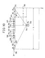
- Fig. 10 is a view which illustrates the arrangement of an optical system for use in a third embodiment.
- reference numeral 110 represents the position indicator
- 121 and 122 represent lasers
- 125 and 126 represent first and second rotary mirrors
- 127 and 128 represent the first and second photosensors
- 171 and 172 represent quarter wavelength plates
- 173 and 174 represent cylindrical lenses
- 175 and 176 represent lenses
- 177 and 178 represent polarizing beam splitters
- 180 represent coordinate input region.
- the position indicator 110 is constituted in such a manner that a mirror portion 114 is disposed on one side surface of a box-like main body 111, the bottom portion of the main body 111 and the same of the mirror portion 114 being arranged such that they can be held in parallel to plane XY.
- a transparent display plate (omitted from illustration) made of synthetic resin is attached to the above-described bottom surface of the mirror portion 114.
- a hair-cross mark showing the center of the mirror portion 114 is provided on the above-described display plate.
- the side external mirror of the mirror portion 114 is inwardly curved at the central portion thereof.
- a coordinate calculation instruction signal generating circuit 115 is provided in the main body 111.
- the coordinate calculation instruction signal generating circuit 115 is connected to a switch 116 disposed on the outer surface of the main body 111 and to an electric circuit to be described later so that when the switch 116 is switched on the coordinate calculation instruction signal generating circuit 115 generates a command signal.
- Each of the lasers 121 and 122 comprises a semiconductor laser.
- the structure is arranged in such a manner that the laser beam emitted by the laser 121 is made incident upon the polarizing beam splitter 177 disposed on X-axis in parallel to plane XY via the lens 175 and the cylindrical lens 173.
- the laser beam which has passed through the polarizing beam splitter 177 is made incident upon the rotational axis of the first rotary mirror 125 in parallel to plane XY via the quarter wavelength plate 171.
- the laser beam emitted by the laser 122 is made incident upon the polarizing beam splitter 178 disposed on X-axis in parallel to plane XY via the lens 176 and the cylindrical lens 174.
- the laser beam which has passed through the polarizing beam splitter 178 is made incident upon the rotational axis of the first rotary mirror 126 in parallel to plane XY via the quarter wavelength plate 172.
- the lens 175 is a lens arranged to have such a focal length that laser beams, which have been reflected by, for example, specific point P1 of the first rotary mirror 125, focused at the center of the coordinate input region 180 on the plane XY.
- the lens 176 is a lens arranged to have such a focal length having laser beams, which have been reflected by, for example, specific point P2 of the second rotary mirror 126, are focused at the center of the coordinate input region 180 on the plane XY.
- the laser beams emitted from the lasers 121 an 122 are stopped by the lenses 175 and 176.
- the intensity of the laser beam made incident upon the photosensors 127 and 128 after the laser beam has been reflected by the mirror portion 114 is strengthened, and irregular reflection of laser beams caused from the mirror portion 114 is prevented.
- the cylindrical lenses 173 and 174 are disposed so as to cause the laser beams emitted from the lasers 121 and 122 to form band-like shapes and so as to cause the plane of the laser beams to be perpendicular to plane XY.
- the laser beams which do not pass through the center axis of the mirror portion 114 are reduced and irregular reflection of the laser beams caused from the mirror portion 114 is prevented by making the laser beams in the form of a band-like shape and perpendicular to the plane XY.
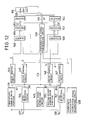
- Fig. 12 is a block diagram of the electric circuit for use in the third embodiment.
- the same components as those according to the first embodiment are given the same reference numerals.
- the difference from the first embodiment lies in that the above-described coordinate calculation instruction signal generating circuit 115 is further provided, and in the structure of the level detection circuits 156 and 157 and the interruption signal generating circuit 158.
- the coordinate calculation instruction signal generating circuit 115 is capable of transmitting coordinate calculation instruction signal J of logic "1" when the switch 116 is switched on.
- the level detection circuits 156 and 157 are structured similarly to each other and each comprise a resistor and an operation amplifier
- the level detection circuit 156 converts an photoelectric current transmitted from the emitter of the first photosensor 127 into voltage V ph1 , the voltage V ph1 being then subjected to comparison with first and second detection reference levels V th1 and V th2 so as to transmit signals A1 and A2. If V th2 ⁇ V th1 and also V th1 ⁇ V ph1 , signal A1 of logic "1" is transmitted to the pulse shaping circuit 144. If V th2 ⁇ V ph1 ⁇ V th1 , signal A2 of logic "1" is transmitted to the pulse shaping circuit 145.
- the level detection circuit 157 converts an photoelectric current transmitted from the emitter of the second photosensor 128 into voltage V ph2 , the voltage V ph2 being then subjected to comparison with first and second detection reference levels V th1 and V th2 so as to transmit signals B1 and B2. If V th1 ⁇ V ph1 , signal B1 of logic "1" is transmitted to the pulse shaping circuit 146. If V th2 ⁇ V ph1 ⁇ V th1 , signal B2 of logic "1" is transmitted to the pulse shaping circuit 147.
- the pulse shaping circuit 144 receives signal A1 and clock signal CK so as to transmit signal C.
- the pulse shaping circuit 145 receives signal A2 and clock signal CK so as to transmit signal E.
- the pulse shaping circuit 146 receives signal B1 and clock signal CK so as to transmit signal D.
- the pulse shaping circuit 147 receives signal B2 and clock signal CK so as to transmit signal F.
- the interruption signal generating circuit 158 is constituted by a flip-flop and a logical circuit and capable of receiving the output signals E and F from the pulse shaping circuits 145 and 147, the coordinate calculation instruction signal J, and the clock signal CK.
- the interruption signal generating circuit 158 is capable of transmitting interruption signal INT.
- the interruption signal generating circuit 158 is further capable of transmitting interruption signal INT to a CPU 155 to be described later after it has caused the interruption signal INT to be logic "1" on condition that the logic value of the coordinate calculation instruction signal J is "1" and either the pulse signal E or F is inputted and then the other pulse signal is inputted or on condition that the logic value of the coordinate calculation instruction signal J is "1" and both the pulse signals E and F are simultaneously inputted.
- the interruption signal generating circuit 158 causes the interruption signal INT to be logic "0” under condition that pulse reset signal R of logic "1" is inputted thereto from the CPU 155.
- the laser beam emitted from the laser 121 is made incident upon the polarizing beam splitter 177 via the lens 175 and the cylindrical lens 173.
- the incidental laser beam is, for example, non-polarizing light
- a laser beam having a polarizing plane in a predetermined direction is made incident upon the first rotary mirror 125 after it has passed through the polarizing beam splitter 117 and the quarter wavelength plate 171.
- the reflected light is made incident upon the polarizing beam splitter 177 after passing through the quarter wavelength plate 171 on the same optical passage as that through which the incidental light beam passes.
- light reflected by the first rotary mirror 125 is caused to be a linear polarized light whose polarized plane is different from incidental light by 90 degrees due to the quarter wavelength plate 171, the liner polarized light being then reflected by the polarizing beam splitter 177 so as to be made incident upon the photosensor 127.
- the laser beam reflected by the mirror portion 114 of the position indicator 110 is similarly detected by the photosensor 127.
- laser beam emitted from the laser 122 and directly reflected by the second rotary mirror 126 and also reflected light by the mirror portion 114 of the position indicator 110 are detected by the second photosensor 128.
- the laser beams emitted from the lasers 121 and 122 may, of course, be laser beams having polarized planes and thereby being transmissible through the polarizing beam splitters 177 and 178.
- the transmitted photoelectric current is increased.
- the degree of increase in the photoelectric current is higher in light directly reflected by the first rotary mirror 125 than in light reflected by the mirror portion 114 of the position indicator 110 by virtue of stronger light intensity due to the reduced degree of light scattering or the like.
- the direct reflected light by the second rotary mirror 126 and reflected light by the mirror portion 114 of the position indicator 110 show the difference that light directly reflected by the second rotary mirror 126 shows stronger light intensity.
- the first detection reference level V th1 is determined with which light directly reflected by the first and second rotary mirrors 125 and 126 can be detected, while the second detection reference level V th2 is determined with which light reflected by the mirror portion 114 of the position indicator 110 can be detected.
- the counter 148 When the first photosensor 127 detects light directly reflected by the first rotary mirror 125, the counter 148 is reset by the signal C transmitted from the pulse shaping circuit 144. When the same detects light reflected by the mirror portion 114 of the position indicator 110, output data from the counter 148 is latched by the register 151 by the signal E transmitted from the pulse shaping circuit 145 so as to be registered as angular data D1 representing incidental angle ⁇ 1 of the laser beam to be made incident upon the first rotary mirror 125.
- the counter 149 is reset by the signal D transmitted from the pulse shaping circuit 146.
- output data from the counter 149 is latched by the register 152 by the signal F transmitted from the pulse shaping circuit 147 so as to be registered as angular data D2 representing incidental angle ⁇ 2 of the laser beam to be made incident upon the second rotary mirror 126.
- angular data D1 and D2 are latched by the registers 153 and 154 by the interruption signal INT.
- the CPU 155 conducts the processings similarly to the first embodiment, X-coordinate and Y-coordinate of point P0 instructed by the position indicator 110 being thus calculated.
- rotary mirrors each of which has a mirror surface are employed as the first and second rotary mirrors 125 and 126, rotary mirrors each of which has a plurality of mirror surfaces may be employed.
- more accurate coordinates can be obtained since the intervals of the detections of the coordinates can be reduced by conducting calculations arranged to correspond to the polygon mirrors.
- the coordinate calculation instruction signal J is supplied to the interruption signal generating circuit 158 via a cable in the third embodiment, it may be transmitted by means of ultrasonic waves or infrared rays.
- Figs. 13(a), 13(b), and 14 are views which illustrate a fourth embodiment of the present invention.
- the structure of this embodiment is the same as the above- described embodiments.
- This embodiment is characterized in that the pair of light source units can be adjusted in accordance with the area of the coordinate input region.
- Fig. 13(a) is a view which illustrates the case in which this embodiment is applied to a relatively narrow coordinate plane, in which the coordinate input apparatus according to the present invention is in a state where the distance between the pair of light sources is relatively short.
- Fig. 13(b) is a view which illustrates the case in which this embodiment is applied to a relatively wide coordinate plane, in which the coordinate input apparatus according to the present invention is in a state where the distance between the pair of light sources is relatively long. That is, a coordinate plane 302′ shown in Fig. 13(b) has a larger size than that of a coordinate plane 302 shown in Fig. 13(a), and distance L′ between specific points P1 and P2 is arranged to be longer than that of the coordinate plate 302. The distance L′ can be manually or automatically specified by relatively moving the right and left light sources along the reference line.
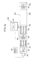
- FIG. 14 is a front elevational view which illustrates a light source portion of the coordinate input apparatus according to the present invention.
- a light source portion 303 comprises a lengthened base member 308 for defining the reference line, a fixed light source unit 304 secured, via a fixed table 309, to the right end portion of the base member 308, and a movable light source unit 305 mounted on a movable table 310 which is capable of moving along the reference line.
- the movable light source portion 303 includes a drive mechanism for automatically moving the movable light source unit 305.
- the drive mechanism comprises a ball screw or a lead screw 311 inserting into the movable table 310 on which the movable light source unit 305 is mounted, an electric motor such as a stepping motor which is coupled, via a coupling 312, to the lead screw 312 for the purpose of rotating the lead screw 312, and a control circuit 314 capable of controlling the rotation of the electric motor 313 so as to determine the distance L between the specific points P1 and P2.
- an electric motor such as a stepping motor which is coupled, via a coupling 312, to the lead screw 312 for the purpose of rotating the lead screw 312, and a control circuit 314 capable of controlling the rotation of the electric motor 313 so as to determine the distance L between the specific points P1 and P2.
- the control circuit 314 is connected to a calculating portion 306 so that the control circuit 314 automatically controls the rotation of the stepping motor 313 and thereby relatively, with respect to the fixed light source 304, moves the movable light source unit 305 mounted on the movable table 310 via the lead screw 311 by inputting the value of L which corresponds to the specified coordinate plane to the calculating portion 306.
- the output terminals of the pair of light source units 304 and 305 are connected to the calculating portion 306 via cables.
- the lead screw 311 is borne by a pair of fixed plates 315 and 316 which are disposed away from each other.
- the movable table 310 is supported by a pair of guide rails 317 and 318 so as to be capable of moving along the reference line.
- the calculating portion 306 includes a CPU so as to calculate, similarly to the above-described embodiments, the coordinate instructed by the position indicator (cursor) 301 in accordance with the angular data ⁇ 1 and ⁇ 2 obtained similarly to those obtained according to the above-described embodiments and data L representing the distance between two points, the data L being previously inputted.
- a CRT 307 or an electronic OHP using transmission type liquid crystal display elements is connected to the CPU so as to visually display the results of the calculations.
- the motor control circuit 314 is also connected to the CPU so as to control the operation of the stepping motor 313 of the light source portion 303 in accordance with data L which has been previously inputted to the CPU.
- the light source portion 303 is positioned on the surface of the top of the input coordinate plane given.
- the distance L (the distance between a pair of specific points P1 and P2) between the pair of light source units 304 and 305 is inputted to the CPU of the calculating portion 306 in accordance with the size of the input coordinate plane.
- the motor control circuit 314 rotates the stepping motor 313 of the light source portion 303 by a predetermined degree so as to move the movable light source unit 305 along the reference line.
- the distance from the movable light source unit 305 to the fixed light source unit 304 is coincided with the specified value L.
- a light reflection type cursor 1 is disposed on the given coordinate plane 302, and the center axis thereof is caused to agree with a desired coordinate P0 (x, y) by using a collimeter.
- the coordinate instruction by using the cursor 301 can be conducted continuously since the angularly scanning speed of the incident light is conducted at high speed.
- the pair of the light source units 304 and 305 are operated so as to angularly scan the incident line and calculate the coordinate P0 (x, y) by conducting a triangulation.
- the distance between the pair of the light source units is automatically determined in accordance with the size of the given coordinate input plane by using the stepping motor and the lead screw.
- the distance L between the light source units can be manually adjusted.
- the structure is so arranged that the movable light source unit is simply moved along the guide rails.
- the calculation and input of the value L are conducted as follows: first, the cursor is disposed at a predetermined point, and ⁇ 1 and ⁇ 2 are obtained by scanning the incident light Then, with the cursor moved from the predetermined point to another point of which the distance to the first point is known, the incident light is scanned so as to obtain ⁇ 1 and ⁇ 2.
- optical structure of the optical unit serves as only examples. A variety of modifications can be available. Furthermore, the light reflection type cursor may also be modified variously. In addition, the moving structure of the movable optical portion is, of course, modified variously.
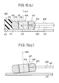
- Figs. 15(a), 15(b), an 15(c) are views which illustrate a modification to the position indicator (the cursor).
- This modification is characterized by a function realized such that the incident light passing toward the center axis of the cursor, which represents the position of the cursor, is selectively reflected so as to return reflected light to the light source.
- another function is effective when the cursor is put on a plane and is manually and continuously moved so as to conduct continuous coordinate inputs, the function being such that reflected light can be kept within the incidental optical passage even if the cursor is inclined with respect to the coordinate plane during its moving.
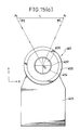
- Fig. 15(a) is a plan view which illustrates an light reflection type cursor according to this embodiment.
- An annular lens member 401 having concentric inner surface 402 and an outer surface 403 is made of an optical material, for example, high refraction factor glass SLF-03 having a refraction factor of 1.83.
- a light reflection layer 404 is formed along the inner surface 402.
- the light reflection layer 404 is manufactured by evaporating metal such as aluminum or metal foil.
- the annular lens member 401 is supported by a support member 405 at the non-effective outer surface thereof and is arranged to be capable of moving along the coordinate plate with the concentric axis retained with respect to the given plane XY.
- a collimating member 406 capable of coinciding central point P1, through which the concentric axis passes, with a specific point on the plane XY.
- the collimating member 406 has a hair cross line to be used for collimating.
- Fig. 15 (b) is a cross sectional view which illustrates the cursor shown in Fig. 14 (a) in such a manner that the same is cross-sectioned by a plane including a line connecting the concentric axis of the annular lens member 401, central point P0, and one of the light source P1.
- the cross cut shape of the inner surface 402 of the annular lens member 401 is parallel to the concentric axis 407.
- the cross cut shape of the outer surface 403 is ground so as to be curved outward with a predetermined curvature.
- the outer surface 403 constitutes a lens surface having an optical axis which is along the radial direction of the annular shape, the curvature of the outer surface being determined so as to cause the focal point of the lens to be positioned on the inner surface 402. It is preferable that the annular lens member 401 be made of a high refraction factor in order to reduce the thickness of the portion between the outer surface 403 and the inner surface 402 and to reduce the size of the cursor. Incident light 409 from a distant light source P1 is reflected by the reflection layer 404, and it is emitted as reflected light 410.
- the collimating member 406 disposed at the central portion of the annular lens member 401 is made of, for example, a fiber optic plate. That is, the collimating member 406 comprises a bottom portion 412 positioned in contact with a XY plane 411, a upper surface 413 which is in parallel to the bottom portion 412, a parallel bundle of the optical fibers for connecting the bottom portion 412 and the upper surface 413, and a hair cross line mark corresponding to central point P0.
- the support member 405 comprises a bottom portion 415 which is positioned which is slidable with respect to the coordinate plane 411, and a fixing portion 416 for securing the non-effective outer surface of the annular lens member 401 such that the concentric axis 407 of the lens member 401 is perpendicular to the bottom portion 415.
- the central point of the cursor that is, the central point P0 of the annular lens member 401 is coincided with a desired specific point for input by using the collimating member 406. Since the collimating member 406 is, as described above, made of the fiber optic plate, the image on the XY coordinate plane positioned in contact with the bottom portion 412 of the collimating member 406 is retained as it is after it has passed through the optical fiber bundle 414 so as to be imaged on the corresponding upper surface 413. Since the thus formed image has no substantial parallax, the desired point can be accurately specified by using the intersection of the hair cross line formed in the collimating member 406, that is, the central point P0 as the collimation with the thus formed image observed.
- incident light beams to be scanned angularly along the coordinate plane are emitted from the light sources P1 and P2 which are positioned away from each other by a predetermined distance L similarly to the above-described embodiments.
- the incident light 409 emitted from light source P1 agrees with an optical axis 408 connecting the central point P0 and the light beam P1
- the reflected light 410 returns to the light source P1 at which it is detected.
- the angle ⁇ 1 defined by the path of the incident light beam 409 and the reflected light beam 410 and the reference line connecting the light sources P1 and P2 is defined.
- angle ⁇ 2 between the optical path and the above-described reference line when the incident light and emitted light are colinear with each other when viewed in a plane manner is defined.
- the bottom surface of the annular lens member 401 can separate from the XY coordinate plane 411 during the movement of the cursor, causing the concentric axis 407 to be temporarily inclined with respect to this plane 411. For example, it can be caused from shake of the user who is holding the support member 405 of the cursor. Even if the concentric axis inclines with respect to the coordinate plane 411, the reflected light beam 410 can inversely pass through the same optical path along which the incident light beam 409 passes when viewed in a plane manner.
- the incident light beam 409 which has passed through the plane including the concentric axis 407 and the radial optical axis is reflected and converged by the surface of the lens formed by the outer surface 403 of the annular lens member 401 so that it is imaged on the reflection layer 404 formed on the inner surface 402.
- the reason for this lies in that the curvature of the lens be determined so as to make the focal point of the lens is positioned on the inner surface 402. Therefore, the light beam reflected by the reflection layer 404 is reflected by the lens outer surface 403 by a so-called cats-eye effect, and is then emitted in parallel to the incident light beam 409 toward the distant light source. Since the incident light beam 409 and the reflected light beam 410 are in parallel to each other, they cannot move away from each other.
- the cursor is constituted by only a cylindrical reflection mirror, light is not, of course, made incident upon perpendicularly to the reflection mirror if the axis of the cylinder is inclined with respect to the coordinate plane. Therefore, the direction of the reflected light beam is different from that of incident light beam. As a result, the reflected light beam cannot return to the distant light source. Therefore, if the axis of the cylinder is inclined, the triangulation in accordance with the coincidence of the passages through which the incident and reflected light beams cannot be conducted in the previous embodiment. However, according to this embodiment, even if the concentric axis is inclined, no substantial problems do occur so that the triangulation can be continued.
- optical structures of the optical units are described only for the examples. They may be modified variously. Furthermore, the light reflection type cursor can be modified from the above-described embodiments. In addition, the movable structure of the movable optical portion can, of course, be modified variously.
- the cursor is, as shown in Fig. 15(a), positioned on the input plate having a finite area.
- the cursor can be positioned on an optional level plane or vertical plane.
- the object of the present invention is to enlarge the size of the apparatus
- the present invention can, of course, be applied to the apparatus of the conventional size, for example, sizes smaller than A0 as the scope of the claims of the present invention.
- the light sources are provided on the reference line and the position indicator is of a reflection type
- the position indicator is also possible to provide the position indicator with a light source emitting light over a wide angular range in the XY plane.
- the rotary mirrors such as mirrors 125,126 in Fig. 1(b) are replaced by optical sensors which are sensitive only for light incident from a predetermined direction and which are rotated so as to scan the XY plane.
- predetermined points P1,P2 are fixed on the reference line and the angles between the reference line and the lines of sight from the points P1,P2 to the position indicator are measured.
- the position indicator may be rotated about its centre axis, two beams are not sufficient for uniquely determining a position on a coordinate plane. If the angle included by two light beams at the position indicator is fixed (e.g.90°) and the light beams meet the reference line at two specific points, the possible positions of the position indicator are located on a circle (Thales' circle). Accordingly, the coordinate of the position indicator on a coordinate line can be detected by calculating the intersection point between said circle and the coordinate line.
- the coordinates of a point on a coordinate plane can be detected by means of three light beams. Then, each pair of light beams defines a circle representing possible locations of the position indicator, and the coordinates can be calculated by determining the intersection point between these circles. Of course, there is still an ambiguity in that a circle and a line or two circles have two intersection points. This ambiguity can however be removed by specifying that the input area of the coordinate plane or the coordinate line is provided only on one side of the reference line.
Landscapes
- Engineering & Computer Science (AREA)
- Physics & Mathematics (AREA)
- General Engineering & Computer Science (AREA)
- General Physics & Mathematics (AREA)
- Theoretical Computer Science (AREA)
- Human Computer Interaction (AREA)
- Electromagnetism (AREA)
- Radar, Positioning & Navigation (AREA)
- Remote Sensing (AREA)
- Length Measuring Devices By Optical Means (AREA)
Applications Claiming Priority (6)
| Application Number | Priority Date | Filing Date | Title |
|---|---|---|---|
| JP63270519A JPH02116917A (ja) | 1988-10-26 | 1988-10-26 | 光学的座標入力装置及びその位置指示器 |
| JP270519/88 | 1988-10-26 | ||
| JP1989058156U JPH0542509Y2 (de) | 1989-05-22 | 1989-05-22 | |
| JP58156/89U | 1989-05-22 | ||
| JP139887/89 | 1989-06-01 | ||
| JP1139887A JPH035805A (ja) | 1989-06-01 | 1989-06-01 | 光学式2次元座標入力装置 |
Publications (3)
| Publication Number | Publication Date |
|---|---|
| EP0366112A2 true EP0366112A2 (de) | 1990-05-02 |
| EP0366112A3 EP0366112A3 (en) | 1990-12-19 |
| EP0366112B1 EP0366112B1 (de) | 1995-03-08 |
Family
ID=27296501
Family Applications (1)
| Application Number | Title | Priority Date | Filing Date |
|---|---|---|---|
| EP89119838A Expired - Lifetime EP0366112B1 (de) | 1988-10-26 | 1989-10-25 | Optische Koordinateneingabevorrichtung und Positionszeiger dafür |
Country Status (3)
| Country | Link |
|---|---|
| US (1) | US5148016A (de) |
| EP (1) | EP0366112B1 (de) |
| DE (1) | DE68921543T2 (de) |
Cited By (10)
| Publication number | Priority date | Publication date | Assignee | Title |
|---|---|---|---|---|
| WO1993004424A1 (en) * | 1991-08-23 | 1993-03-04 | Sybiz Software Pty. Ltd. | Remote sensing computer pointer |
| EP0532125A1 (de) * | 1991-09-12 | 1993-03-17 | Robert Jan Proper | Messgerät zur Bestimmung der Position eines beweglichen Elementes bezüglich einer Referenz |
| EP0577308A3 (de) * | 1992-06-30 | 1994-05-04 | Ibm | |
| WO1994017467A1 (fr) * | 1993-01-20 | 1994-08-04 | Alexandr Jurievich Romanenko | Dispositif d'exploitation manuelle d'ordinateur |
| EP0772148A3 (de) * | 1995-10-26 | 1998-08-05 | Sick AG | Optische Erfassungseinrichtung |
| GB2339096A (en) * | 1998-06-29 | 2000-01-12 | Jonathan Brookhouse | Laser tracking system |
| EP1510836A3 (de) * | 2003-08-29 | 2006-11-29 | Agilent Technologies, Inc. | Bestimmung der Position eines retroreflektierenden Objekts |
| DE10003855B4 (de) * | 1999-01-29 | 2010-12-16 | Ricoh Co., Ltd. | Koordinateneingabevorrichtung, Koordinateneingabeverfahren und Anzeigetafelsystem |
| CN1924774B (zh) * | 2005-06-30 | 2012-03-07 | 罗技欧洲公司 | 在各种表面上的光学位移检测的方法和装置 |
| CN102841710A (zh) * | 2011-05-09 | 2012-12-26 | 林宏宇 | 感测方法与装置 |
Families Citing this family (21)
| Publication number | Priority date | Publication date | Assignee | Title |
|---|---|---|---|---|
| JPH05127809A (ja) * | 1991-04-19 | 1993-05-25 | Sharp Corp | 三次元空間座標入力装置 |
| JP3400485B2 (ja) * | 1993-03-23 | 2003-04-28 | 株式会社ワコム | 光学式位置検出装置および光学式座標入力装置 |
| US5502568A (en) * | 1993-03-23 | 1996-03-26 | Wacom Co., Ltd. | Optical position detecting unit, optical coordinate input unit and optical position detecting method employing a pattern having a sequence of 1's and 0's |
| JPH07261920A (ja) * | 1994-03-17 | 1995-10-13 | Wacom Co Ltd | 光学式位置検出装置および光学式座標入力装置 |
| US5729475A (en) * | 1995-12-27 | 1998-03-17 | Romanik, Jr.; Carl J. | Optical system for accurate monitoring of the position and orientation of an object |
| US6396005B2 (en) | 1998-06-15 | 2002-05-28 | Rodgers Technology Center, Inc. | Method and apparatus for diminishing grid complexity in a tablet |
| JP4083941B2 (ja) * | 1999-09-03 | 2008-04-30 | 株式会社リコー | 座標入力装置 |
| WO2001057635A1 (en) * | 2000-02-02 | 2001-08-09 | Fujitsu Limited | Optical position detector |
| JP4393030B2 (ja) * | 2000-04-14 | 2010-01-06 | 富士通株式会社 | 光学式位置検出装置及び記録媒体 |
| JP2004341892A (ja) * | 2003-05-16 | 2004-12-02 | Fuji Xerox Co Ltd | 指示入力装置、指示入力方法、及びプログラム |
| JP4164423B2 (ja) * | 2003-08-29 | 2008-10-15 | キヤノン株式会社 | センシング部とポインティングデバイスとを含み構成される装置 |
| US7359041B2 (en) * | 2003-09-04 | 2008-04-15 | Avago Technologies Ecbu Ip Pte Ltd | Method and system for optically tracking a target using a triangulation technique |
| US7360703B2 (en) * | 2004-09-23 | 2008-04-22 | Ut-Battelle, Llc | Laser scanning system for object monitoring |
| US7473884B2 (en) * | 2005-04-21 | 2009-01-06 | Avago Technologies Ecbu Ip (Singapore) Pte. Ltd. | Orientation determination utilizing a cordless device |
| US7609249B2 (en) * | 2005-04-21 | 2009-10-27 | Avago Technologies Ecbu Ip (Singapore) Pte. Ltd. | Position determination utilizing a cordless device |
| US20070109527A1 (en) * | 2005-11-14 | 2007-05-17 | Wenstrand John S | System and method for generating position information |
| US7796119B2 (en) * | 2006-04-03 | 2010-09-14 | Avago Technologies General Ip (Singapore) Pte. Ltd. | Position determination with reference |
| CN101825971B (zh) * | 2009-03-02 | 2012-07-04 | 林志雄 | 激光扫描输入装置 |
| TWI461988B (zh) * | 2011-06-15 | 2014-11-21 | Pixart Imaging Inc | 光學觸控裝置 |
| CN104423722A (zh) * | 2013-09-04 | 2015-03-18 | 中强光电股份有限公司 | 光学触控装置 |
| JP2016201002A (ja) * | 2015-04-10 | 2016-12-01 | 船井電機株式会社 | 位置検出装置及び空間入力装置 |
Family Cites Families (6)
| Publication number | Priority date | Publication date | Assignee | Title |
|---|---|---|---|---|
| US2592329A (en) * | 1945-08-23 | 1952-04-08 | Schlumberger Prospection | Optical apparatus for measuring by deflection |
| US3632191A (en) * | 1970-03-26 | 1972-01-04 | Magnavne Inc | Mirror and lens assembly |
| DE2355616C3 (de) * | 1973-11-07 | 1979-05-03 | Rainer Dipl.-Ing. Erhardt | Vorrichtung zum Übertragen graphisch vorgegebener Daten von einem Tableau auf einen Rechner |
| GB1466471A (en) * | 1974-09-25 | 1977-03-09 | Cetec Systems Ltd | Optical digistising system |
| US4294543A (en) * | 1979-11-13 | 1981-10-13 | Command Control & Communications Corporation | Optical system for developing point coordinate information |
| DE3344478A1 (de) * | 1983-12-08 | 1985-06-20 | Erwin Sick Gmbh Optik-Elektronik, 7808 Waldkirch | Retroreflektor |
-
1989
- 1989-10-25 DE DE68921543T patent/DE68921543T2/de not_active Expired - Fee Related
- 1989-10-25 EP EP89119838A patent/EP0366112B1/de not_active Expired - Lifetime
-
1990
- 1990-10-02 US US07/591,516 patent/US5148016A/en not_active Expired - Lifetime
Cited By (17)
| Publication number | Priority date | Publication date | Assignee | Title |
|---|---|---|---|---|
| WO1993004424A1 (en) * | 1991-08-23 | 1993-03-04 | Sybiz Software Pty. Ltd. | Remote sensing computer pointer |
| EP0532125A1 (de) * | 1991-09-12 | 1993-03-17 | Robert Jan Proper | Messgerät zur Bestimmung der Position eines beweglichen Elementes bezüglich einer Referenz |
| US5298737A (en) * | 1991-09-12 | 1994-03-29 | Proper R J | Measuring apparatus for determining the position of a movable element with respect to a reference |
| EP0577308A3 (de) * | 1992-06-30 | 1994-05-04 | Ibm | |
| US6091405A (en) * | 1992-06-30 | 2000-07-18 | International Business Machines Corporation | Input device |
| WO1994017467A1 (fr) * | 1993-01-20 | 1994-08-04 | Alexandr Jurievich Romanenko | Dispositif d'exploitation manuelle d'ordinateur |
| EP0772148A3 (de) * | 1995-10-26 | 1998-08-05 | Sick AG | Optische Erfassungseinrichtung |
| GB2339096A (en) * | 1998-06-29 | 2000-01-12 | Jonathan Brookhouse | Laser tracking system |
| DE10003855B4 (de) * | 1999-01-29 | 2010-12-16 | Ricoh Co., Ltd. | Koordinateneingabevorrichtung, Koordinateneingabeverfahren und Anzeigetafelsystem |
| EP1510836A3 (de) * | 2003-08-29 | 2006-11-29 | Agilent Technologies, Inc. | Bestimmung der Position eines retroreflektierenden Objekts |
| US7633633B2 (en) | 2003-08-29 | 2009-12-15 | Avago Technologies Ecbu Ip (Singapore) Pte. Ltd. | Position determination that is responsive to a retro-reflective object |
| CN1924774B (zh) * | 2005-06-30 | 2012-03-07 | 罗技欧洲公司 | 在各种表面上的光学位移检测的方法和装置 |
| CN102841710A (zh) * | 2011-05-09 | 2012-12-26 | 林宏宇 | 感测方法与装置 |
| US9012828B2 (en) | 2011-05-09 | 2015-04-21 | Cho-Yi Lin | Method and device for sensing a position of an object |
| CN105183240A (zh) * | 2011-05-09 | 2015-12-23 | 林卓毅 | 感测方法与装置 |
| CN102841710B (zh) * | 2011-05-09 | 2016-01-27 | 林卓毅 | 感测方法与装置 |
| US9606673B2 (en) | 2011-05-09 | 2017-03-28 | Cho-Yi Lin | Method and device for sensing a position of an object |
Also Published As
| Publication number | Publication date |
|---|---|
| EP0366112B1 (de) | 1995-03-08 |
| DE68921543T2 (de) | 1995-07-20 |
| DE68921543D1 (de) | 1995-04-13 |
| EP0366112A3 (en) | 1990-12-19 |
| US5148016A (en) | 1992-09-15 |
Similar Documents
| Publication | Publication Date | Title |
|---|---|---|
| EP0366112B1 (de) | Optische Koordinateneingabevorrichtung und Positionszeiger dafür | |
| US6362468B1 (en) | Optical unit for detecting object and coordinate input apparatus using same | |
| US5319387A (en) | Apparatus for specifying coordinates of a body in three-dimensional space | |
| JP5797282B2 (ja) | ターゲット装置及び方法 | |
| US4420261A (en) | Optical position location apparatus | |
| US5298737A (en) | Measuring apparatus for determining the position of a movable element with respect to a reference | |
| US8243015B2 (en) | Virtual data entry device | |
| CN102067075A (zh) | 检测触摸表面上多个对象的位置 | |
| CN103092419A (zh) | 用于检测多个触摸的触摸屏 | |
| WO1994015173A1 (en) | Scanning sensor | |
| EP2793042B1 (de) | Positioniervorrichtung mit einem Lichtstrahl | |
| JP2896183B2 (ja) | 光学式複数2次元座標同時入力装置 | |
| CN102022979A (zh) | 三维光学感测系统 | |
| US3457646A (en) | Laser beam operated x-y table | |
| JPH09133873A (ja) | 固体物体の向きを決定するための光学装置 | |
| JPH0542509Y2 (de) | ||
| JP3504293B2 (ja) | 移動体の位置方位測定装置 | |
| JPS581120A (ja) | テレセントリツク光線を発生する装置および物体の寸法または位置を測定する方法 | |
| JP2865754B2 (ja) | 光学式2次元座標入力装置及び座標入力用ペン | |
| JPH096521A (ja) | ペン入力装置 | |
| JP2011159270A (ja) | 位置検出装置 | |
| JPH02155024A (ja) | 三次元座標入力装置及びその位置指示器 | |
| JP2544789B2 (ja) | 光学式変位測定装置 | |
| JPH05187832A (ja) | 計測装置 | |
| JP2004110442A (ja) | 座標入力装置 |
Legal Events
| Date | Code | Title | Description |
|---|---|---|---|
| PUAI | Public reference made under article 153(3) epc to a published international application that has entered the european phase |
Free format text: ORIGINAL CODE: 0009012 |
|
| AK | Designated contracting states |
Kind code of ref document: A2 Designated state(s): DE FR GB IT |
|
| PUAL | Search report despatched |
Free format text: ORIGINAL CODE: 0009013 |
|
| AK | Designated contracting states |
Kind code of ref document: A3 Designated state(s): DE FR GB IT |
|
| 17P | Request for examination filed |
Effective date: 19901231 |
|
| 17Q | First examination report despatched |
Effective date: 19930714 |
|
| GRAA | (expected) grant |
Free format text: ORIGINAL CODE: 0009210 |
|
| AK | Designated contracting states |
Kind code of ref document: B1 Designated state(s): DE FR GB IT |
|
| REF | Corresponds to: |
Ref document number: 68921543 Country of ref document: DE Date of ref document: 19950413 |
|
| ITF | It: translation for a ep patent filed | ||
| ET | Fr: translation filed | ||
| PLBE | No opposition filed within time limit |
Free format text: ORIGINAL CODE: 0009261 |
|
| STAA | Information on the status of an ep patent application or granted ep patent |
Free format text: STATUS: NO OPPOSITION FILED WITHIN TIME LIMIT |
|
| 26N | No opposition filed | ||
| PGFP | Annual fee paid to national office [announced via postgrant information from national office to epo] |
Ref country code: FR Payment date: 19971017 Year of fee payment: 9 |
|
| PG25 | Lapsed in a contracting state [announced via postgrant information from national office to epo] |
Ref country code: FR Free format text: LAPSE BECAUSE OF NON-PAYMENT OF DUE FEES Effective date: 19990630 |
|
| REG | Reference to a national code |
Ref country code: FR Ref legal event code: ST |
|
| PGFP | Annual fee paid to national office [announced via postgrant information from national office to epo] |
Ref country code: GB Payment date: 20011002 Year of fee payment: 13 |
|
| REG | Reference to a national code |
Ref country code: GB Ref legal event code: IF02 |
|
| PG25 | Lapsed in a contracting state [announced via postgrant information from national office to epo] |
Ref country code: GB Free format text: LAPSE BECAUSE OF NON-PAYMENT OF DUE FEES Effective date: 20021025 |
|
| GBPC | Gb: european patent ceased through non-payment of renewal fee | ||
| PG25 | Lapsed in a contracting state [announced via postgrant information from national office to epo] |
Ref country code: IT Free format text: LAPSE BECAUSE OF NON-PAYMENT OF DUE FEES;WARNING: LAPSES OF ITALIAN PATENTS WITH EFFECTIVE DATE BEFORE 2007 MAY HAVE OCCURRED AT ANY TIME BEFORE 2007. THE CORRECT EFFECTIVE DATE MAY BE DIFFERENT FROM THE ONE RECORDED. Effective date: 20051025 |
|
| PGFP | Annual fee paid to national office [announced via postgrant information from national office to epo] |
Ref country code: DE Payment date: 20051027 Year of fee payment: 17 |
|
| PG25 | Lapsed in a contracting state [announced via postgrant information from national office to epo] |
Ref country code: DE Free format text: LAPSE BECAUSE OF NON-PAYMENT OF DUE FEES Effective date: 20070501 |