EP0366140A1 - Nähmaschine - Google Patents
Nähmaschine Download PDFInfo
- Publication number
- EP0366140A1 EP0366140A1 EP89119940A EP89119940A EP0366140A1 EP 0366140 A1 EP0366140 A1 EP 0366140A1 EP 89119940 A EP89119940 A EP 89119940A EP 89119940 A EP89119940 A EP 89119940A EP 0366140 A1 EP0366140 A1 EP 0366140A1
- Authority
- EP
- European Patent Office
- Prior art keywords
- needle
- motor
- signal
- sewing machine
- speed
- Prior art date
- Legal status (The legal status is an assumption and is not a legal conclusion. Google has not performed a legal analysis and makes no representation as to the accuracy of the status listed.)
- Granted
Links
Images


Classifications
-
- D—TEXTILES; PAPER
- D05—SEWING; EMBROIDERING; TUFTING
- D05B—SEWING
- D05B69/00—Driving-gear; Control devices
- D05B69/36—Devices for stopping drive when abnormal conditions occur, e.g. thread breakage
Definitions
- the present invention relates to a sewing machine, and especially relates to a sewing machine for industrial use such as sewing of thick and heavy cloth.
- a sewing machine 1 is driven by an electric motor 3 via a belt 2.
- a pedal sensor 5 detects depth of the control pedal 4.
- a speed signal generator 7 generates speed signals corresponding to output data from the pedal sensor 5.
- a controller 6 controls the motor 3 to rotate in a speed corresponding to press-down degree of the pedal 4, basing on the speed signal from the speed signal generator 7.
- the pedal 4 is restored to the neutral position, the rotation speed of the motor 3 is decreased.
- rotation of the motor 3 is retained in a slow rotation speed until a needle position detector 8 detects that the needle reaches a first position to be stopped.
- the needle position detector 8 issues an output signal, the motor 3 is stopped of the rotation and driving of the sewing machine 1 is also stopped.
- the above-mentioned operations are generally called the regular position stopping of the sewing machine.
- the motor 3 rotates in a constant speed and when it stops the needle is stopped at a second position by receiving a signal from the needle position detector 8. At the second position, the needle is drawn out upward from the cloth (needle-up position), thereby to enable the cloth being taken out and in the sewing machine 1.
- the above-mentioned conventional sewing machine having the regular position stopping mode is designed for light load, and in case it would be used for a heavier load it would have a disadvantage of overload of the motor 3 and inherent locking of the needle at a first stitch when a heavy cloth is newly inserted in the sewing machine.
- Such a disadvantageous phenomenon is especially conspicuous in case of using a thick needle for sewing thick and heavy cloth.
- sewing can not be done and the motor 3 may burn-out when such a trouble is left as it is. Accordingly, it has been necessary to increase power of the motor or to give an impetus to the sewing machine at a first stitch by human hand for sewing heavy load such as thick and heavy cloth by the conventional sewing machine.
- a sewing machine in accordance with the present invention comprises: a motor for driving the sewing machine; needle position detecting means for detecting position of a needle of the sewing machine and outputting needle position signal; speed control means for controlling rotation speed of the motor; and sequence control means for controlling driving and stopping of the motor responding to depth of a pedal and outputting a signal to the speed control means, thereby driving the motor in a reversal direction for a predetermined angle when a needle-down signal of first stitch does not come with a predetermined time period from a start of said driving.
- the needle When the falling speed of needle for the first stitch is longer than the predetermined time, the needle can not penetrate the cloth because of, for example, thickness and heaviness of the cloth. Accordingly, in the sewing machine in accordance with the present invention, the motor is once rotated in a reversal direction as a preliminary motion by control of the sequence control means and thereafter in the normal direction again. Thereby, the needle is given an impetus to penetrate the thick and heavy cloth without increasing the power of the motor.
- FIGs. 1, 2 and 3 A first preferred embodiment of a sewing machine in accordance with the present invention is described with reference to FIGs. 1, 2 and 3.
- FIG.1 is a block diagram showing the construction of the sewing machine in accordance with a first, a second and a third embodiments.
- a driving controller 21 outputs a signal corresponding to the signal of the pedal sensor 5 for detecting the motion of the pedal 4 of the conventional sewing machine shown in FIG.9.
- Output ends of the driving controller 21 is connected via an AND circuit 22 to a flip-flop 23 and a control input of a first switch 24.
- Output end of a first speed setter 25 is connected to a speed controller 26 via the first swtich 24.
- printed circuit board of the first speed setter 25 is contained in the pedal sensor 5 and outputs a signal of speed value which is previously set and corresponding to depth (pressed-down degree) of the pedal 4.
- a second speed setter 27 is connected to the afore-mentioned speed controller 28 via a second switch 28.
- a speed judging circuit 29 receives signal from a speed signal generator 7 which is mounted on the motor 3 and is connected to a sequence controller 34 via AND circuits 30, 31 and 32.
- a needle position detector 8 is provided on the sewing machine 1 and outputs a needle-up signal NU and a needle-down signal ND. These signals are input to the sequence controller 34 via the AND circuits 31 and 32.
- the needle-down signal ND is also input to a needle signal judging circuit 33.
- the needle signal judging circuit 33 outputs a signal when a front edge of the needle-down signal ND is detected to be longer a predetermined time period after pressing down of the pedal 4.
- a D.C. brush-less motor is used as the motor 3.
- the afore-mentioned speed signal generator 7 outputs two signals, phases relation thereof are shifted each other, and the afore-mentioned speed controller 26 judges the direction of rotation of the motor 3 by from the phase relation of the two signals and controls the direction of the rotation of the motor 3.
- the motor 3 drives the sewing machine 1 via the belt 2.
- the driving controller 21 contained in the pedal sensor 5 When the pedal 4 is pressed down, the driving controller 21 contained in the pedal sensor 5 outputs a signal and at the same time the first speed setter 25 sets the speed value in digital data.
- the first speed setter 25 outputs a digital signal for controlling the rotation speed of the motor 3 corresponding to the depth of stepping down of the pedal 4.
- the driving controller 21 turns on the first switch 24 for connecting the first speed setter 25 to the speed controller 26.
- the speed controller 26 controls the direction of the rotation of the motor 3 by comparing the two signals from the speed signal generator 7 to rotate the motor 3 in the normal direction. And the speed controller 26 controls speed corresponding to the signal given from the first speed setter 25 when it receives a command for rotation such as normal-direction-ROT signal which is given from the sequence controller 34 and transmitted on an output line ROT in case of pressing down of the pedal 4. At that time, the flip-flop 23 is reset. Thereby, the motor 3 continues to rotate in the rotation speed set by the second speed setter 27, even after restoration of the pedal 4 to the neutral position and the driving controller 21's stopping to issue its output.
- a command for rotation such as normal-direction-ROT signal which is given from the sequence controller 34 and transmitted on an output line ROT in case of pressing down of the pedal 4.
- the rotation speed set by the second speed setter 27 is selected to be appropriately slow for enabling immediate stopping of the needle when the needle position detector 8 detects reaching of the needle to the position of stopping.
- the driving controller 21 stops to issue the output, the rotation speed of the motor 3 is suddenly reduced.
- the speed judging circuit 29 judges that the rotation speed of the motor 3 has been sufficiently reduced to a speed by which the motor 3 can be stopped at once, the flip-flop 23 is reset by the signal from the needle position detector 8 to a rest signal input terminal thereof.
- the second switch 28 is turned off and thereby the motor 3 is stopped to rotate.
- the sequence controller 34 controls the rotation in normal and inverse directions of the motor 3, by outputting the signal ROT on the output line ROT.
- the ROT signal is changed high and low corresponding to the existence and non-existence of the needle-down signal ND, respectively in one period of the stitch, given through the needle signal judging circuit 33.
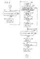
- the driving controller 21 When the pedal 4 is pressed down forward, the driving controller 21 outputs a signal (Step 101).
- the needle signal judging circuit 33 which is a counter, starts to count a time period from the time of start of driving of the motor 3 to a time when the front edge of the signal ND of needle-down position is input by receiving the signal from the driving controller 21 (Step 103). In case that the counted time period is longer than the predetermined time period (in Step 104), the needle signal judging circuit 33 outputs a signal to the sequence controller via the AND circuit 30. Thereby, the sequence controller 34 outputs a SPD signal on the output line SPD (Step 105).
- the second switch 28 is turned off by receiving the SPD signal. Thereby, the signal from the second speed setter 27 is input to the speed controller 26.
- the ROT signal from the sequence controller 34 is outputted to reverse the direction of the rotation of the motor 3 from the normal direction (Step 105).
- "high" level of the ROT signal corresponds to the normal direction of the rotation of the motor 3 and "low” level to the reverse direction.
- the needle position detector 8 detects reach of the needle to the needle-up position
- the needle position detector 8 outputs the needle-up signal NU to the sequence controller 34 via the AND circuit 31 (Step 106).
- the sequence controller 34 stops issue of the SPD signal and outputs the ROT signal at high level thereby to rotate the motor 3 in the normal direction (Step 107).
- the speed controller 26 continues the same operation of the above-mentioned case when the pedal 4 is pressed down.
- Steps 108 to 111 designates the known stopping operation of the sewing machine, and thereby, details are omitted.
- the motor 3 is rotated in the reverse direction. And the rotation lasts until the reach of needle to the needle-up position. And after the reach of needle, the motor is rotated in the normal direction thereby to give the impetus to penetrate the thick and heavy cloth.
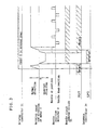
- FIG.4 is a flow chart showing the operation of the sequence controller 34 in the second embodiment
- FIG.5 is a timing chart thereof.
- the hard ware of the second embodiment of substantially the same as that of the first embodiment shown in FIG.1.
- the sequence controller 34 outputs the signal for rotating the motor 3 in the reverse direction as shown in FIG.4 during the time period T as shown in FIG.5.
- the sequence controller 34 has a changeable timer shown in the step 106′.
- the angle for rotating the motor 3 in the reversal direction can easily be selected by adjustment of the timer.
- a function of the needle position detector 8 for detecting that the needle reaches the needle-up position can be omitted from the first embodiment.
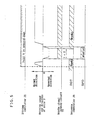
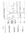
- FIG.6 is a flow chart showing the operation of the sequence controller 34 in the third embodiment
- FIG.7 is a timing chart thereof.
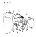
- FIG.8 is a perspective view showing the details of the needle position detector 8 having two needle-up positions to be detected. One is fixed and the other is adjustable. Other elements for constituting the sewing machine is substantially the same as the afore-mentioned first and second embodiments.
- the needle position detector 8 is disposed on a pulley 35 and comprises: a needle position sensor 36 for generating needle-up signal; a first reflector 37 mounted on a shaft of the pulley 35 at an adjustable predetermined position for reflecting a light from the needle position sensor 36; and a second reflector 38 mounted on the shaft at a fixed predetermined position near the upper dead point of the crank of the sewing machine 1.
- the needle position sensor 36 outputs a first needle-up signal N1 when the first reflector 37 passes in front thereof, and a second needle-up signal N2 (which corresponds to the needle-up signal NU in the first and second embodiments) when the second reflector 38 passes in front thereof.
- Operations of the third embodiment is substantially the same as that of the first embodiment. However, different point is that the signal for rotating the motor 3 in the reversal direction is continued to be outputted until the first needle-up signal N1 is outputted.
- the needle-up signal NU corresponding to the second needle-up signal N2 in the third embodiment which is outputted from the fixed needle sensor (reflector) near the upper dead point is used without any relation to the sequence operation of the sewing machine for stopping the rotation of the motor 3 in the reversal direction. Thereby, the rotation angle of the motor in the reversal direction is fixed.
- the adjustable needle sensor such as reflector 37 is used. Thereby, the rotation angle of the motor in the reversal direction is also adjustable in the third embodiment.
- the sequence controller 34 controls the driving and stopping of the motor 3 by using the output signal SPD and controls the direction thereof by using the output signal ROT.
- the ROT signals of rotation direction of the motor 3 with the SPD signals of the driving and stopping of the motor 3.
- other speed controllers and switches such as third and fourth are usable for controlling the motor in normal and reversal direction respectively different independent rotation speed.
Landscapes
- Engineering & Computer Science (AREA)
- Mechanical Engineering (AREA)
- Textile Engineering (AREA)
- Sewing Machines And Sewing (AREA)
Applications Claiming Priority (2)
| Application Number | Priority Date | Filing Date | Title |
|---|---|---|---|
| JP273520/88 | 1988-10-28 | ||
| JP63273520A JP2636375B2 (ja) | 1988-10-28 | 1988-10-28 | ミシン駆動装置 |
Publications (2)
| Publication Number | Publication Date |
|---|---|
| EP0366140A1 true EP0366140A1 (de) | 1990-05-02 |
| EP0366140B1 EP0366140B1 (de) | 1994-07-13 |
Family
ID=17529002
Family Applications (1)
| Application Number | Title | Priority Date | Filing Date |
|---|---|---|---|
| EP89119940A Expired - Lifetime EP0366140B1 (de) | 1988-10-28 | 1989-10-26 | Nähmaschine |
Country Status (4)
| Country | Link |
|---|---|
| US (1) | US5018466A (de) |
| EP (1) | EP0366140B1 (de) |
| JP (1) | JP2636375B2 (de) |
| DE (1) | DE68916746D1 (de) |
Cited By (10)
| Publication number | Priority date | Publication date | Assignee | Title |
|---|---|---|---|---|
| GB2267717A (en) * | 1992-06-09 | 1993-12-15 | Brother Ind Ltd | Rotation control device for sewing machine motor |
| DE4218868A1 (de) * | 1992-06-09 | 1993-12-16 | Brother Ind Ltd | Drehsteuervorrichtung für eine Nähmaschine |
| US5304901A (en) * | 1990-11-28 | 1994-04-19 | Brother Kogyo Kabushiki Kaisha | Rotation control device for sewing motor |
| US5562059A (en) * | 1992-10-27 | 1996-10-08 | Mitsubishi Denki Kabushiki Kaisha | Apparatus and method for controlling sewing machine |
| DE4134532C2 (de) * | 1990-11-10 | 2000-11-16 | Brother Ind Ltd | Antriebseinrichtung für eine Nähmaschine |
| DE4345370C2 (de) * | 1992-10-27 | 2001-02-22 | Mitsubishi Electric Corp | Nähmaschinensteuervorrichtung für eine Nähmaschine |
| US8925473B2 (en) | 2007-11-09 | 2015-01-06 | Vsm Group Ab | Thread cut with variable thread consumption in a sewing machine |
| CN104294481A (zh) * | 2014-09-24 | 2015-01-21 | 上海鲍麦克斯电子科技有限公司 | 一种工业缝纫机数字控制系统及控制方法 |
| US8960112B2 (en) | 2013-02-01 | 2015-02-24 | Vsm Group Ab | Stitching system and method for stitch stop embellishments |
| US8985038B2 (en) | 2010-06-09 | 2015-03-24 | Vsm Group Ab | Feeder movement compensation |
Families Citing this family (6)
| Publication number | Priority date | Publication date | Assignee | Title |
|---|---|---|---|---|
| JP2796180B2 (ja) * | 1990-07-16 | 1998-09-10 | 松下電器産業株式会社 | ミシン駆動装置 |
| EP0505663B1 (de) * | 1991-03-29 | 1995-07-19 | COMELZ S.p.A. | Elektrische Antriebsvorrichtung für eine Nähmaschine |
| US5540161A (en) * | 1995-08-29 | 1996-07-30 | Quick Technologies, Inc. | Sewing apparatus having a sandwich synchronizer |
| CN101809216B (zh) * | 2007-08-30 | 2015-10-21 | Vsm集团股份公司 | 针脚数据对象的定位 |
| US20110168070A1 (en) * | 2007-08-30 | 2011-07-14 | Pierre Lanquist | Sewing machine modification tools |
| US8606390B2 (en) * | 2007-12-27 | 2013-12-10 | Vsm Group Ab | Sewing machine having a camera for forming images of a sewing area |
Citations (3)
| Publication number | Priority date | Publication date | Assignee | Title |
|---|---|---|---|---|
| US4195585A (en) * | 1977-03-30 | 1980-04-01 | Hitachi, Ltd. | Protection apparatus for electric sewing mechine |
| EP0176599A1 (de) * | 1984-03-02 | 1986-04-09 | Matsushita Electric Industrial Co., Ltd. | Antriebsvorrichtung für nähmaschine |
| GB2184568A (en) * | 1985-11-06 | 1987-06-24 | Matsushita Electric Industrial Co Ltd | Motor controller for a sewing machine |
Family Cites Families (3)
| Publication number | Priority date | Publication date | Assignee | Title |
|---|---|---|---|---|
| JPS55129085A (en) * | 1979-03-26 | 1980-10-06 | Janome Sewing Machine Co Ltd | Electronic sewing machine |
| US4498078A (en) * | 1981-01-23 | 1985-02-05 | Motokazu Yoshimura | Sewing machine with a voice warning device |
| US4490656A (en) * | 1983-06-30 | 1984-12-25 | The Singer Company | Overload protection in a motor control system |
-
1988
- 1988-10-28 JP JP63273520A patent/JP2636375B2/ja not_active Expired - Lifetime
-
1989
- 1989-10-26 DE DE68916746T patent/DE68916746D1/de not_active Expired - Lifetime
- 1989-10-26 EP EP89119940A patent/EP0366140B1/de not_active Expired - Lifetime
- 1989-10-27 US US07/427,348 patent/US5018466A/en not_active Expired - Fee Related
Patent Citations (3)
| Publication number | Priority date | Publication date | Assignee | Title |
|---|---|---|---|---|
| US4195585A (en) * | 1977-03-30 | 1980-04-01 | Hitachi, Ltd. | Protection apparatus for electric sewing mechine |
| EP0176599A1 (de) * | 1984-03-02 | 1986-04-09 | Matsushita Electric Industrial Co., Ltd. | Antriebsvorrichtung für nähmaschine |
| GB2184568A (en) * | 1985-11-06 | 1987-06-24 | Matsushita Electric Industrial Co Ltd | Motor controller for a sewing machine |
Cited By (12)
| Publication number | Priority date | Publication date | Assignee | Title |
|---|---|---|---|---|
| DE4134532C2 (de) * | 1990-11-10 | 2000-11-16 | Brother Ind Ltd | Antriebseinrichtung für eine Nähmaschine |
| US5304901A (en) * | 1990-11-28 | 1994-04-19 | Brother Kogyo Kabushiki Kaisha | Rotation control device for sewing motor |
| GB2267717A (en) * | 1992-06-09 | 1993-12-15 | Brother Ind Ltd | Rotation control device for sewing machine motor |
| DE4218868A1 (de) * | 1992-06-09 | 1993-12-16 | Brother Ind Ltd | Drehsteuervorrichtung für eine Nähmaschine |
| US5562059A (en) * | 1992-10-27 | 1996-10-08 | Mitsubishi Denki Kabushiki Kaisha | Apparatus and method for controlling sewing machine |
| US5653186A (en) * | 1992-10-27 | 1997-08-05 | Mitsubishi Denki Kabushiki Kaisha | Apparatus and method for controlling sewing machine |
| DE4345370C2 (de) * | 1992-10-27 | 2001-02-22 | Mitsubishi Electric Corp | Nähmaschinensteuervorrichtung für eine Nähmaschine |
| US8925473B2 (en) | 2007-11-09 | 2015-01-06 | Vsm Group Ab | Thread cut with variable thread consumption in a sewing machine |
| US8985038B2 (en) | 2010-06-09 | 2015-03-24 | Vsm Group Ab | Feeder movement compensation |
| US8960112B2 (en) | 2013-02-01 | 2015-02-24 | Vsm Group Ab | Stitching system and method for stitch stop embellishments |
| CN104294481A (zh) * | 2014-09-24 | 2015-01-21 | 上海鲍麦克斯电子科技有限公司 | 一种工业缝纫机数字控制系统及控制方法 |
| CN104294481B (zh) * | 2014-09-24 | 2016-10-19 | 上海鲍麦克斯电子科技有限公司 | 一种工业缝纫机数字控制系统及控制方法 |
Also Published As
| Publication number | Publication date |
|---|---|
| JPH02119895A (ja) | 1990-05-07 |
| US5018466A (en) | 1991-05-28 |
| EP0366140B1 (de) | 1994-07-13 |
| DE68916746D1 (de) | 1994-08-18 |
| JP2636375B2 (ja) | 1997-07-30 |
Similar Documents
| Publication | Publication Date | Title |
|---|---|---|
| EP0366140A1 (de) | Nähmaschine | |
| US4338556A (en) | Electronically controlled thread-cutting machine | |
| US4972134A (en) | Motor control circuit for automatic washer | |
| US4516514A (en) | Circuit arrangement for controlling sewing machine speed and for positioning sewing needle | |
| US4332208A (en) | Sewing machine speed control circuit | |
| US4602581A (en) | Sewing machine controlling apparatus | |
| US5603272A (en) | Two-needle type sewing machine | |
| KR850001705B1 (ko) | 재봉틀 속도 설정장치 | |
| US4955306A (en) | Sewing machine | |
| US4980619A (en) | Speed control device for sewing machine | |
| JP2562912B2 (ja) | ミシン駆動装置 | |
| US5566632A (en) | Control method for automatic sewing machine and apparatus thereof | |
| CN1699665B (zh) | 缝纫机电动机的控制装置及其控制方法 | |
| JPH10225583A (ja) | モータ制御装置 | |
| JPS6128356B2 (de) | ||
| KR920000679Y1 (ko) | 자동사절 재봉기의 콘트롤 회로 | |
| US5532559A (en) | Apparatus for and method of providing continuous driving current to a commutatorless motor | |
| JP2547452B2 (ja) | 工業用ミシンの位置制御装置 | |
| JPH04240479A (ja) | ミシン制御装置 | |
| JP3302519B2 (ja) | ミシン駆動装置 | |
| JP2700550B2 (ja) | 電子ミシンの止め縫い制御装置 | |
| JP2879275B2 (ja) | 模様縫いにおける自動糸切りミシン | |
| JPS5946625B2 (ja) | ミシンの回転速度記憶装置 | |
| KR960015664B1 (ko) | 재봉틀모터의 회전제어장치 | |
| JP3459530B2 (ja) | ステッピングモータの駆動回路 |
Legal Events
| Date | Code | Title | Description |
|---|---|---|---|
| PUAI | Public reference made under article 153(3) epc to a published international application that has entered the european phase |
Free format text: ORIGINAL CODE: 0009012 |
|
| AK | Designated contracting states |
Kind code of ref document: A1 Designated state(s): DE GB |
|
| 17P | Request for examination filed |
Effective date: 19900605 |
|
| 17Q | First examination report despatched |
Effective date: 19930618 |
|
| GRAA | (expected) grant |
Free format text: ORIGINAL CODE: 0009210 |
|
| AK | Designated contracting states |
Kind code of ref document: B1 Designated state(s): DE GB |
|
| REF | Corresponds to: |
Ref document number: 68916746 Country of ref document: DE Date of ref document: 19940818 |
|
| PG25 | Lapsed in a contracting state [announced via postgrant information from national office to epo] |
Ref country code: DE Effective date: 19941014 |
|
| PLBE | No opposition filed within time limit |
Free format text: ORIGINAL CODE: 0009261 |
|
| STAA | Information on the status of an ep patent application or granted ep patent |
Free format text: STATUS: NO OPPOSITION FILED WITHIN TIME LIMIT |
|
| 26N | No opposition filed | ||
| PGFP | Annual fee paid to national office [announced via postgrant information from national office to epo] |
Ref country code: GB Payment date: 20011024 Year of fee payment: 13 |
|
| REG | Reference to a national code |
Ref country code: GB Ref legal event code: IF02 |
|
| PG25 | Lapsed in a contracting state [announced via postgrant information from national office to epo] |
Ref country code: GB Free format text: LAPSE BECAUSE OF NON-PAYMENT OF DUE FEES Effective date: 20021026 |
|
| GBPC | Gb: european patent ceased through non-payment of renewal fee |