EP0366471B1 - Verbundschlauchaufbau - Google Patents
Verbundschlauchaufbau Download PDFInfo
- Publication number
- EP0366471B1 EP0366471B1 EP89311072A EP89311072A EP0366471B1 EP 0366471 B1 EP0366471 B1 EP 0366471B1 EP 89311072 A EP89311072 A EP 89311072A EP 89311072 A EP89311072 A EP 89311072A EP 0366471 B1 EP0366471 B1 EP 0366471B1
- Authority
- EP
- European Patent Office
- Prior art keywords
- hose
- cord
- fibrous
- disposed
- rubber
- Prior art date
- Legal status (The legal status is an assumption and is not a legal conclusion. Google has not performed a legal analysis and makes no representation as to the accuracy of the status listed.)
- Expired - Lifetime
Links
- 239000002131 composite material Substances 0.000 title claims description 6
- 238000010276 construction Methods 0.000 title 1
- 230000003014 reinforcing effect Effects 0.000 claims description 16
- 229920001971 elastomer Polymers 0.000 claims description 14
- 239000005060 rubber Substances 0.000 claims description 14
- 229910000831 Steel Inorganic materials 0.000 claims description 9
- 239000010959 steel Substances 0.000 claims description 9
- 239000000945 filler Substances 0.000 claims description 8
- 229920002994 synthetic fiber Polymers 0.000 claims description 5
- 239000000835 fiber Substances 0.000 description 5
- 239000012530 fluid Substances 0.000 description 4
- 239000002184 metal Substances 0.000 description 4
- 230000002787 reinforcement Effects 0.000 description 3
- 238000005452 bending Methods 0.000 description 2
- 230000005484 gravity Effects 0.000 description 2
- 229920000297 Rayon Polymers 0.000 description 1
- 229920002978 Vinylon Polymers 0.000 description 1
- 230000001133 acceleration Effects 0.000 description 1
- 230000002411 adverse Effects 0.000 description 1
- 230000005540 biological transmission Effects 0.000 description 1
- 230000015572 biosynthetic process Effects 0.000 description 1
- 238000010073 coating (rubber) Methods 0.000 description 1
- 230000006835 compression Effects 0.000 description 1
- 238000007906 compression Methods 0.000 description 1
- 239000000470 constituent Substances 0.000 description 1
- 230000010339 dilation Effects 0.000 description 1
- 238000010030 laminating Methods 0.000 description 1
- 229920001778 nylon Polymers 0.000 description 1
- 239000004033 plastic Substances 0.000 description 1
- 229920000728 polyester Polymers 0.000 description 1
- 239000002964 rayon Substances 0.000 description 1
- 238000000926 separation method Methods 0.000 description 1
- 238000006467 substitution reaction Methods 0.000 description 1
- 238000004804 winding Methods 0.000 description 1
Images
Classifications
-
- F—MECHANICAL ENGINEERING; LIGHTING; HEATING; WEAPONS; BLASTING
- F16—ENGINEERING ELEMENTS AND UNITS; GENERAL MEASURES FOR PRODUCING AND MAINTAINING EFFECTIVE FUNCTIONING OF MACHINES OR INSTALLATIONS; THERMAL INSULATION IN GENERAL
- F16L—PIPES; JOINTS OR FITTINGS FOR PIPES; SUPPORTS FOR PIPES, CABLES OR PROTECTIVE TUBING; MEANS FOR THERMAL INSULATION IN GENERAL
- F16L11/00—Hoses, i.e. flexible pipes
- F16L11/04—Hoses, i.e. flexible pipes made of rubber or flexible plastics
- F16L11/08—Hoses, i.e. flexible pipes made of rubber or flexible plastics with reinforcements embedded in the wall
Definitions
- This invention relates to a composite hose for use in marine loading, according to the first part of claim 1.
- a typical example of the known hoses of the type described is disclosed in EP-A-0,032,352, wherein a hose constructed to have two different reinforcing layers and a filler layer interposed between a core tube and a cover, whereby the hose is rendered resistent to collapse, flexure and distortion caused by external force and pressure.
- One of the reinforcements results from laminating a synthetic fibre cord over the core and acts as a pressure-resistant layer, and the other is adapted to be a kinking-proof layer formed by spirally winding a wire strand on to the fibrous layer.
- Another known hose is reinforced in a two-layered structure with steel cords.
- the first-mentioned hose of a combination reinforcement is not wholly satisfactory as it is liable to plastically deform upon kinking.
- the last-mentioned, steel-reinforced hose is restorable even after kinking due to the steel cord being greater in plastic strain than the wire strand.
- the latter hose is susceptible to interlaminar separation because the steel cord is likely to locally buckle at a position adjacent to the cover as the hose is subject to bending and eventual flattening.
- the steel-reinforced hose has a further drawback in that it involves objectionable pressure buildup while in surging, leading to insufficient durability. This is attributable to the steel cord being less stretchable in the warpwise and weftwise directions and rather prone to prevent the hose against dilation, hence pressure relaxation.
- the present invention is directed to the provision of a new composite hose which is highly resistant to kinking, restorable even after kinking, relaxable from pressure on surging and free from buckling.
- the hose according to the invention contributes to reliable and efficient transportation or otherwise handling of fluids under adverse conditions particularly at sea or on ships.
- the invention is directed to a composite hose comprised essentially of a core rubber tube; a first reinforcing layer formed of fibrous cord of a synthetic fibre disposed on said core tube; a second reinforcing layer formed of stranded steel metallic cord disposed on said first reinforcing layer; a filler rubber disposed on said second reinforcing layer; and a rubber cover disposed on said filler rubber, whereas the total thickness of said core tube and said first and second reinforcing layers is substantially equal to or smaller than one-half the total thickness of said core tube, said first and second reinforcing layers, said filler rubber and said cover, characterised in that said fibrous and metallic cords intersect each other, and said fibrous cord and said metallic cored are oriented at an angle of from 35 to 55 degrees and at an angle of from 70 to 90 degrees, respectively, with respect to the axial direction of said hose, with the difference of such angles being greater than 35 degrees.
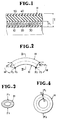
- Figure 1 is a longitudinal radial cross-sectional view, of a hose provided in accordance with the present invention.
- Figure 2 is a fragmentary schematic view showing the manner in which the hose when flexed is subjected to various forces.
- Figure 3 is a cross-sectional view taken along the line III-III of Figure 2.
- Figure 4 is a schematic view explanatory of a strain distribution in the hose on flattening.
- the hose H essentially comprises a first reinforcing layer 20 and a second reinforcing layer 30 superposed one on the other over a core tube rubber 10.
- Designated at 40 and 50 are a filler rubber and a cover rubber, respectively, disposed peripherally over the second layer 30.
- the first layer 20 is constituted by a fibrous cord of a selected synthetic fibre and the second layer 30 by a metallic cord of a selected steel strand.
- synthetic fibres include fibrous filaments of polyesters, nylons, vinylons, rayons and the like. Suitable steel strands are those commonly accepted in the art.
- the fibrous and metallic cords may conveniently be preformed into a screen-like structure with the use of a rubber coating. Any known rubbers are useful for the layers 10, 40, 50 in their respective thicknesses.
- the hose H should be assembled such that the first three layers 10, 20, 30 are defined in their total thickness to. be equal to or less than half the overall hose thickness as viewed at T1 and T in Figure 1. This arrangement ensures enhanced performance of the hose H in a manner to be described.
- the first layer 20 is laid to absorb internal pressure developed axially of the hose, while the second layer 30 relaxes circumferentially exerted internal pressure.
- the fibrous cord should preferably be oriented at an angle in the range of 35 to 55° and the metallic cord at an angle in the range of 70 to 90°, respectively, with respect to an axial direction of the hose.
- the two cords should be held in opposed, intersected relation to each other with the difference of angles set above 35°.
- Each of the first and second layers 20, 30, may be at least of a two-ply formation.
- Fibrous cords of wider angles than 55° would make the resulting fibre layer susceptible to axial stress that is requisite to multiple cordage. Departures of fibrous cords from 35° and of metallic cords from 70° would invite reduced resistance to circumferential stress, entailing multiplied cord in the metal layer. In the case of differences of angles not exceeding 35° between the first and second layers, the metal layer would get too rigid and thus interfere with the fibre layer in stretching.
- the hose according to the invention provided with a fibre layer of lower modulus coefficient and a metal layer of higher modulus coefficient, is designed to reduce in overall modulus coefficient compared to a hose in which two steel reinforcements are disposed.
- the correlation between the modulus coefficient and the pressure increase is expressed by the equation I.
- ⁇ H a g V0
- ⁇ H pressure increase on surging
- g transmission speed of pressure wave
- V0 flow speed of fluid
- ⁇ H can be seen to reduce with the decrease in E, provided that the magnitude of modulus coefficients alone is varied. This is interpreted to mean that because the whole hose H is small in modulus coefficient, the fibre layer 20 is stretchable enough to increase the hose volume and thus absorb undue pressure on surging.
- Figure 4 is taken to represent the hose H as stressed under the flattening forces F1, F2.
- compression strains are generated in the hose at the external side and tensile strains at the internal side, both sorts of strains being concentrated maximum, respectively, in the outermost and innermost circumferences.
- the hose can be kept, by the action of tensile strains developed by the metal layer, from getting buckled on flexure even at a relatively small curvature.
Landscapes
- Engineering & Computer Science (AREA)
- General Engineering & Computer Science (AREA)
- Mechanical Engineering (AREA)
- Rigid Pipes And Flexible Pipes (AREA)
- Laminated Bodies (AREA)
Claims (2)
- Verbundschlauch (H) mit:
einem Kernrohr (10) aus Gummi;
einer ersten Verstärkungsschicht (20) aus einem faserförmigen Strang einer synthetischen Faser, die auf dem Kernrohr (10) angeordnet ist;
einer zweiten Verstärkungsschicht (30) aus einem metallischen Stahlseilstrang, der auf der ersten Verstärkungsschicht (20) angeordnet ist;
einem Füllgummi (40), das auf der zweiten Verstärkungsschicht (30) angeordnet ist;
und einer Deckschicht (50) aus Gummi, die auf dem Füllgummi (40) angeordnet ist, wobei die Gesamtdicke (T₁) des Kernrohres (10) und der ersten (20) und zweiten (30) Verstärkungsschichten halbwegs gleich zur Hälfte oder kleiner als die Hälfte der Gesamtdicke (T) des Kernrohres (10), der ersten (20) und zweiten (30) Verstärkungsschichten, des Füllgummis (40) und der Deckschicht (50) ist,
dadurch gekennzeichnet,
daß sich die faserförmigen und metallischen Stränge durchkreuzen, und daß der faserförmige Strang und der metallische Strang in bezug auf die axiale Richtung des Schlauchs (H) jeweils in einem Winkel von 35 - 55 Grad und einem Winkel von 70 - 90 Grad orientiert sind, wobei die Differenz der Winkel größer als 35 Grad ist. - Schlauch nach Anspruch 1, worin die ersten (20) und zweiten (30) Verstärkungsschichten jeweils aus mindestens zwei Schichten gebildet werden.
Applications Claiming Priority (2)
| Application Number | Priority Date | Filing Date | Title |
|---|---|---|---|
| JP272093/88 | 1988-10-28 | ||
| JP63272093A JP2647464B2 (ja) | 1988-10-28 | 1988-10-28 | ホース |
Publications (2)
| Publication Number | Publication Date |
|---|---|
| EP0366471A1 EP0366471A1 (de) | 1990-05-02 |
| EP0366471B1 true EP0366471B1 (de) | 1993-01-07 |
Family
ID=17508983
Family Applications (1)
| Application Number | Title | Priority Date | Filing Date |
|---|---|---|---|
| EP89311072A Expired - Lifetime EP0366471B1 (de) | 1988-10-28 | 1989-10-26 | Verbundschlauchaufbau |
Country Status (4)
| Country | Link |
|---|---|
| US (1) | US5014751A (de) |
| EP (1) | EP0366471B1 (de) |
| JP (1) | JP2647464B2 (de) |
| HU (1) | HU209195B (de) |
Families Citing this family (3)
| Publication number | Priority date | Publication date | Assignee | Title |
|---|---|---|---|---|
| EP0740098B1 (de) * | 1995-04-28 | 1999-10-27 | The Yokohama Rubber Co., Ltd. | Verstärkter Druckschlauch |
| US7069956B1 (en) | 2003-10-23 | 2006-07-04 | Mosier James W | Marina piping |
| GB0414022D0 (en) * | 2004-06-23 | 2004-07-28 | Dunlop Oil & Marine Ltd | Hybrid hose reinforcements |
Family Cites Families (19)
| Publication number | Priority date | Publication date | Assignee | Title |
|---|---|---|---|---|
| US1052106A (en) * | 1911-05-11 | 1913-02-04 | Frank D Voorhees | Hose. |
| GB191317748A (en) * | 1913-08-02 | 1914-07-23 | Frank Reddaway | Improvements in and connected with Hose for Conveying Fluid Under Pressure and for other purposes. |
| US2730133A (en) * | 1951-02-02 | 1956-01-10 | Dunlop Rubber Co | Reinforced fireproof hose |
| FR1140376A (fr) * | 1955-09-28 | 1957-07-19 | Procédé de fabrication de corps tubulaires en polytétrafluoréthylène | |
| DE1910598A1 (de) * | 1969-03-01 | 1970-09-10 | Teves Gmbh Alfred | Druckmittelschlauch |
| GB1360040A (en) * | 1971-12-16 | 1974-07-17 | Uniroyal Ltd | Hose |
| US3791415A (en) * | 1972-05-15 | 1974-02-12 | Hydraflow Supply Inc | Resilient flexible hose |
| FR2319830A1 (fr) * | 1975-07-29 | 1977-02-25 | Kleber Colombes | Tuyaux flexibles |
| JPS5356715A (en) * | 1976-11-02 | 1978-05-23 | Bridgestone Corp | Buoyant hose for fluid handling |
| US4249971A (en) * | 1979-04-25 | 1981-02-10 | Amerace Corporation | Process for making elastomeric hose |
| AU541052B2 (en) * | 1980-01-10 | 1984-12-13 | Goodyear Tire And Rubber Company, The | Hose structure |
| US4474217A (en) * | 1980-03-31 | 1984-10-02 | The Goodyear Tire & Rubber Company | Hose structure |
| FR2490774A1 (fr) * | 1980-09-25 | 1982-03-26 | Delasco Sa | Tube pour pompes peristaltiques |
| USRE32508E (en) * | 1981-06-29 | 1987-09-22 | The Goodyear Tire & Rubber Company | Hose structure |
| US4384595A (en) * | 1981-09-14 | 1983-05-24 | Parker-Hannifin Corporation | Hose construction |
| US4431031A (en) * | 1982-03-29 | 1984-02-14 | Amco Corporation | Pre-rinse hose |
| US4488577A (en) * | 1982-09-30 | 1984-12-18 | Parker-Hannifin Corporation | Fire resistant hose |
| US4585035A (en) * | 1983-12-19 | 1986-04-29 | The Goodyear Tire & Rubber Company | Reinforced hose |
| US4706712A (en) * | 1986-03-27 | 1987-11-17 | Dayco Products, Inc. | Hose construction |
-
1988
- 1988-10-28 JP JP63272093A patent/JP2647464B2/ja not_active Expired - Fee Related
-
1989
- 1989-10-25 US US07/426,431 patent/US5014751A/en not_active Expired - Fee Related
- 1989-10-26 EP EP89311072A patent/EP0366471B1/de not_active Expired - Lifetime
- 1989-10-27 HU HU895471A patent/HU209195B/hu not_active IP Right Cessation
Also Published As
| Publication number | Publication date |
|---|---|
| JPH02118293A (ja) | 1990-05-02 |
| HU209195B (en) | 1994-03-28 |
| EP0366471A1 (de) | 1990-05-02 |
| HU895471D0 (en) | 1990-02-28 |
| JP2647464B2 (ja) | 1997-08-27 |
| US5014751A (en) | 1991-05-14 |
| HUT55677A (en) | 1991-06-28 |
Similar Documents
| Publication | Publication Date | Title |
|---|---|---|
| US5176180A (en) | Composite tubular member with axial fibers adjacent the side walls | |
| EP0524206B1 (de) | Rohrelement aus verbundwerkstoff mit mehreren zellen | |
| US4403631A (en) | Flexible pipe | |
| EP1677040B1 (de) | Schlauchkupplung | |
| US8225820B2 (en) | Hose | |
| JPH061114B2 (ja) | 内部圧力を受けても顕著な長さ変化を起こさない可撓導管 | |
| JP2659277B2 (ja) | かみ合わせ外装層を含む可撓性管状導管 | |
| BR0214550B1 (pt) | conduto flexìvel maleável submarino de transporte de um fluido. | |
| US20020017332A1 (en) | Brake hose | |
| EP0366471B1 (de) | Verbundschlauchaufbau | |
| JP2000510779A (ja) | 圧縮可能なマンドレル上で不均衡に織られた繊維を巻くことにより得られる複合材料における管状の部材 | |
| US4148342A (en) | Hose structure and method for making | |
| EP0213816B1 (de) | Mit optimierten Windungswinkeln gewickelter Verbundbauteil | |
| JP3228386B2 (ja) | 可撓性流体輸送管 | |
| JP3228368B2 (ja) | 可撓性流体輸送管の製造方法 | |
| JP4433626B2 (ja) | マリンホース | |
| JPH0229348Y2 (de) | ||
| JPH05248571A (ja) | 補強ホース | |
| EP0333370A1 (de) | Schläuche | |
| GB2073360A (en) | Improvements in or relating to a reinforced rubber tube | |
| JPH03125091A (ja) | 布巻きホース | |
| JPS61201982A (ja) | マリンホ−ス | |
| JPH034877Y2 (de) | ||
| JPH07151273A (ja) | 流体輸送管 | |
| JPH0435661Y2 (de) |
Legal Events
| Date | Code | Title | Description |
|---|---|---|---|
| PUAI | Public reference made under article 153(3) epc to a published international application that has entered the european phase |
Free format text: ORIGINAL CODE: 0009012 |
|
| 17P | Request for examination filed |
Effective date: 19891107 |
|
| AK | Designated contracting states |
Kind code of ref document: A1 Designated state(s): FR GB IT |
|
| 17Q | First examination report despatched |
Effective date: 19910222 |
|
| GRAA | (expected) grant |
Free format text: ORIGINAL CODE: 0009210 |
|
| ITF | It: translation for a ep patent filed | ||
| AK | Designated contracting states |
Kind code of ref document: B1 Designated state(s): FR GB IT |
|
| ET | Fr: translation filed | ||
| PLBE | No opposition filed within time limit |
Free format text: ORIGINAL CODE: 0009261 |
|
| STAA | Information on the status of an ep patent application or granted ep patent |
Free format text: STATUS: NO OPPOSITION FILED WITHIN TIME LIMIT |
|
| 26N | No opposition filed | ||
| REG | Reference to a national code |
Ref country code: GB Ref legal event code: IF02 |
|
| PGFP | Annual fee paid to national office [announced via postgrant information from national office to epo] |
Ref country code: FR Payment date: 20041008 Year of fee payment: 16 |
|
| PGFP | Annual fee paid to national office [announced via postgrant information from national office to epo] |
Ref country code: GB Payment date: 20041020 Year of fee payment: 16 |
|
| PG25 | Lapsed in a contracting state [announced via postgrant information from national office to epo] |
Ref country code: IT Free format text: LAPSE BECAUSE OF NON-PAYMENT OF DUE FEES;WARNING: LAPSES OF ITALIAN PATENTS WITH EFFECTIVE DATE BEFORE 2007 MAY HAVE OCCURRED AT ANY TIME BEFORE 2007. THE CORRECT EFFECTIVE DATE MAY BE DIFFERENT FROM THE ONE RECORDED. Effective date: 20051026 Ref country code: GB Free format text: LAPSE BECAUSE OF NON-PAYMENT OF DUE FEES Effective date: 20051026 |
|
| GBPC | Gb: european patent ceased through non-payment of renewal fee |
Effective date: 20051026 |
|
| PG25 | Lapsed in a contracting state [announced via postgrant information from national office to epo] |
Ref country code: FR Free format text: LAPSE BECAUSE OF NON-PAYMENT OF DUE FEES Effective date: 20060630 |
|
| REG | Reference to a national code |
Ref country code: FR Ref legal event code: ST Effective date: 20060630 |