EP0366508B1 - Griff für Drehstangenverschluss mit integriertem Schloss, insbesondere für Kraftfahrzeuge - Google Patents
Griff für Drehstangenverschluss mit integriertem Schloss, insbesondere für Kraftfahrzeuge Download PDFInfo
- Publication number
- EP0366508B1 EP0366508B1 EP19890402674 EP89402674A EP0366508B1 EP 0366508 B1 EP0366508 B1 EP 0366508B1 EP 19890402674 EP19890402674 EP 19890402674 EP 89402674 A EP89402674 A EP 89402674A EP 0366508 B1 EP0366508 B1 EP 0366508B1
- Authority
- EP
- European Patent Office
- Prior art keywords
- handle
- espagnolette
- support member
- pin
- planet
- Prior art date
- Legal status (The legal status is an assumption and is not a legal conclusion. Google has not performed a legal analysis and makes no representation as to the accuracy of the status listed.)
- Expired - Lifetime
Links
- 238000007789 sealing Methods 0.000 claims description 7
- 238000000465 moulding Methods 0.000 claims description 3
- 229920003002 synthetic resin Polymers 0.000 claims description 3
- 239000000057 synthetic resin Substances 0.000 claims description 3
- 230000000717 retained effect Effects 0.000 claims description 2
- 230000003213 activating effect Effects 0.000 claims 2
- 230000004913 activation Effects 0.000 claims 2
- 239000002184 metal Substances 0.000 claims 1
- 230000008901 benefit Effects 0.000 description 3
- 239000000463 material Substances 0.000 description 3
- 229910000831 Steel Inorganic materials 0.000 description 2
- 230000000694 effects Effects 0.000 description 2
- 238000004519 manufacturing process Methods 0.000 description 2
- 239000010959 steel Substances 0.000 description 2
- 230000015572 biosynthetic process Effects 0.000 description 1
- 230000000881 depressing effect Effects 0.000 description 1
- 238000001746 injection moulding Methods 0.000 description 1
- 238000003754 machining Methods 0.000 description 1
- 238000012986 modification Methods 0.000 description 1
- 230000004048 modification Effects 0.000 description 1
- 230000002787 reinforcement Effects 0.000 description 1
- 229920002994 synthetic fiber Polymers 0.000 description 1
Images



Classifications
-
- E—FIXED CONSTRUCTIONS
- E05—LOCKS; KEYS; WINDOW OR DOOR FITTINGS; SAFES
- E05B—LOCKS; ACCESSORIES THEREFOR; HANDCUFFS
- E05B13/00—Devices preventing the key or the handle or both from being used
- E05B13/10—Devices preventing the key or the handle or both from being used formed by a lock arranged in the handle
-
- E—FIXED CONSTRUCTIONS
- E05—LOCKS; KEYS; WINDOW OR DOOR FITTINGS; SAFES
- E05B—LOCKS; ACCESSORIES THEREFOR; HANDCUFFS
- E05B83/00—Vehicle locks specially adapted for particular types of wing or vehicle
- E05B83/02—Locks for railway freight-cars, freight containers or the like; Locks for the cargo compartments of commercial lorries, trucks or vans
- E05B83/08—Locks for railway freight-cars, freight containers or the like; Locks for the cargo compartments of commercial lorries, trucks or vans with elongated bars for actuating the fastening means
- E05B83/10—Rotary bars
Definitions
- the present invention relates to the closing of swing doors of vehicles and more particularly of heavy vehicle doors as well as those of containers and similar objects which include cremone bolts preferably embedded and whose bolt-forming elements are engaged in strikes forming part of the fixed structure of the container vehicle or other elements.
- the invention creates a new handle which has an integrated locking device comprising only a very small number of parts which can be easily produced by injection molding in plastic material, which makes it possible to manufacture both at a high quality. and a low cost since no machining operation is necessary and the assembly of the parts is, moreover, very simple.
- the invention also creates a handle which can be dismantled so that it can optionally be changed or allows the change of all or part of the cremone bolt contrary to what is practiced in known devices.
- Another considerable advantage of the invention resides in the fact that the operation of the integrated locking device is such that it cannot be damaged even if the operator performs false operations, for example when he closes or attempts to close. the door while the locking device has been previously returned to the locked position.
- Yet another advantage of the invention resides in the fact that the handle with integrated locking device can be operated with one hand and brought, after rotation of the bolt rod, into a position for which the operator benefits from maximum force to take off the door, which is very important with regard to tight seal doors such as there are on refrigerated vehicles.
- FR-A-2 584 764 discloses a handle for a lever with an integrated locking device, in particular for a vehicle, and this document was taken as a basis in the drafting of the appended main claim.
- the pivoting body forms a handle and the lever defines a pusher disposed in this handle. It is thus possible to take the handle with one hand to exert traction on the door while pressing the button with a finger.
- the present invention therefore relates to a lever handle with integrated locking device according to claim 1.
- Various other characteristics of the invention will moreover emerge from the detailed description which follows.
- Fig. 1 shows the rear of a heavy vehicle using the handle of the inventive lever.
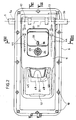
- Fig. 2 is a front view of the handle.
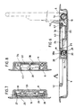
- Fig. 3 is a longitudinal section seen along line III-III of FIG. 2.
- Fig. 4 is a plan view of the operating part of the lock seen along line IV-IV of FIG. 3.
- Fig. 5 is a plan view, on a larger scale, of a detail of embodiment appearing in FIG. 4.
- Fig. 6 is a longitudinal section seen along line VI-VI of FIG. 2.
- Fig. 7 is a cross section seen along line VII-VII of FIG. 4.
- Fig. 8 is a cross section seen along line VIII-VIII of FIG. 2.
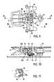
- Fig. 9 is a partial plan view similar to FIG. 4 illustrating a development of the invention.
- Fig. 10 is a section seen along the line X-X of FIG. 9 and illustrating a characteristic position.
- Fig. 11 is a sectional view taken along line XI-XI of FIG. 9.
- Fig. 12 is a view similar to FIG. 9 showing another characteristic position.
- Fig. 13 is a section seen along the line XIII-XIII of FIG. 12.
- 1 designates a heavy-duty type road vehicle, the rear panel of which is closed by two doors 2, 3 hinged by hinges 4.
- the doors 2, 3 are each provided with a cremone bolt 5 whose bolts engage in keepers 6, 7.
- Each lever 5 is controlled by a handle 8. It is advantageous, as shown by the tearing of FIG. 1, that the cremone bolts are inserted into the thickness of the doors 2, 3 and that only the handles 8 which control them appear.
- the handle comprises a support 9 having the shape of a bowl when the handle is embedded, this support being fixed by screws or rivets 10 to the external face of the door 2 or 3.
- the cremone bolt 5 crosses the lateral sides of the support 9 .
- the handle comprises a body 11 made of molded material preferably of synthetic material which delimits, at one end, a handle 12 for its operation.
- the body 11 forms a half-shell 13 in which it is advantageous that a gasket 14 is inserted during the molding of the body 11.
- the gasket 14 is advantageously metallic, for example steel stainless, and has a female thread 15.
- the cremone bolt consists of two rods 5a, 5b, one, for example the rod 5a, having one male socket, and the other, the rod 5b, a female socket, as shown in FIG. 4.
- the rods 5a, 5b have holes 16 (fig. 3), for example four in number, through which screws 17 have passed, the position of which is illustrated in FIGS. 2 and 3.
- Each screw 17 passes through a half-shell 18, for example made of molded synthetic resin, then the hole 16 of one of the rods 5a, 5b of the cremone bolt and is screwed into the internal thread 15. In this way, the half-shell 18, the rods 5a, 5b and the body 11 are rigidly connected to each other.
- Fig. 3 shows that the screws 17 occupy an inclined position for example at 45 ° relative to the bottom of the support 9 when the body 11 is in the closed position as illustrated in FIG. 3. In this position, the screw heads 17 are turned towards the bottom of the support 9 and are therefore inaccessible.
- the body 11 is pivoted by driving the rods 5a, 5b of the cremone bolt, this pivoting taking place at an angle of approximately 90 °, then the heads of the screws 17 are accessible (fig. 6), which allows, if necessary, disassembly of the handle to make it possible to replace either this handle or one or the other of the rods 5a, 5b of the lever.
- the body 11 supports, below the handle 12, an axis 19 on which a lever with two branches 20 is articulated, one of the branches of which, that designated by 20a, forms a pusher 21 which is level with the upper edge 9a of the support 9.
- the other branch 20b (fig. 3) of the lever 20 extends substantially at right angles to the branch 20a and is disposed on the path of a bolt 22 of a lock barrel 23 carried by a recessed part 24 of the body 1.
- the lock barrel 23 is intended to be controlled by means of a key, not shown.
- the pin 19 supports on both sides of the lever with two branches 20 of the pawls 25, 26 of molded material with which are associated torsion springs 27, 28 tending to rotate them in the direction for which a projecting part 29 which 'they have (fig. 6) is engaged below hooks 30 formed by the bottom of the support 9 and whose top 30a is inclined to form a cam.
- Fig. 4 shows that the springs 27, 28 wound on the axis 19 have one end 27a, respectively 28a, bearing under a bearing surface 11a respectively 11b of the body 11 and one end 27b respectively 28b engaged in a hole 31, 32 of the pawls 25, 26.
- the pawls 25, 26 are retained by lateral stops 33, 34 formed on the sides of the branch 20a of the lever with two branches 20 and constituting unidirectional actuating means (FIGS. 4 and 6).
- the branch 20a is itself thus brought into abutment against a fallen edge 35 (FIGS. 3 and 4) of the part of the body 11 which covers the pawls 25, 26 as well as the lever with two branches 20, with the exception of the pusher 21.
- the body 11 is shaped to delimit, between the hollowed-out part 24 and the half-shell 13, a housing 36 whose bottom 37 has a slot 38.
- a finger 39 formed from the bottom of the support 9 is passed through the slot 38 and has a buttonhole 40 intended for fitting a sealing plummet 41 (FIGS. 2 and 3).
- the body 11 supports, between the housing 36 and the half-shell 13, an axis 42 for the articulation of a flap 43 covering the housing 36 and the recessed part 24 and, consequently, the lock barrel 23.
- the body 11 is connected to the support 9, by means of one or protrusions by springs 44 illustrated in FIGS. 2 and 6 in the form of tension springs.
- the springs 44 therefore tend to hold the body 11 so that it takes support in the bottom of the support 9 and that its top is thus at the same level as the external edge of the support.
- the bottom of the support 9 has tabs 45, 46 pierced with buttonholes 47 for the establishment of a padlock 48, the stirrup 49 of which prevents pushing of the pusher 21, which constitutes an additional security element to those which are described in the foregoing and the operation of which is explained below.
- a return spring is associated with the flap 43 to keep it in closed position.
- the handle 12 can easily be grasped with a hand, a finger of which presses on the pusher 21.
- the handle 12 after pivoting of the body 11 makes it possible to exert a significant traction on the door because it can be well held in hand in a position for which the operator can develop significant force.
- the force of the tension springs 44 can be provided sufficient for the folding down of the body 11 to take place automatically.
- the pawls 25, 26 bear against the cam 30a of the hooks 30, which makes them pivot against the action of the springs 27, 28 which then bring their projecting parts 29 in engagement with said hooks 30.
- the pusher 21 is mounted on an auxiliary axis 51 parallel to the axis 19 carrying the pawls 25, 26.
- the axis 19 is provided between the pawls with a planet carrier 52 of which it is integral in rotation and which has an axis 53 extending in a plane perpendicular to the axis 19.
- the axis 53 is used for the articulation of a satellite disc 54 of which a finger 55 (fig. 13) is normally held in abutment against a fixed stop 56 by a spiral spring 57.
- the satellite 54 is provided, on its top, with a stop 58 located on the path of the bolt 22 of the barrel 23.
- the satellite 54 has, in addition, a notch 59 and a lateral stop 60 which is located opposite the branch 20b of the pusher 21 when the finger 55 is in abutment against the stop 56.
- the lateral stop 60 of the satellite can be pushed by the branch 20b of the pusher 21, branch which is in the position illustrated in FIGS. 12 and 13.
- this has the effect of tilting the planet carrier which drives the axis 19 and which consequently releases the pawls 25, 26 from the hooks 30.
- the loop 12 can therefore be actuated as described in the foregoing.
- the barrel 23 is turned by means of a key not shown, which rotates the bolt 22 in the direction of the arrow f2 to bring it from the position illustrated in fig . 12 to that illustrated in FIG. 9.
- Figs. 9 and 10 show that the pusher 21 can then be actuated from the position illustrated in solid lines to the position illustrated in phantom without producing any command, that is to say that this pusher is crazy around the axis who wears it.
- the support 9 can protrude above the exterior face of the doors 2, 3 when the cremone bolts 5 are themselves disposed outside of said doors.
- the relatively complex shape of the body 11 allows the formation on its underside of stiffening ribs 50, while the top can be smooth, which is particularly suitable for the production of said body 11 by molding. synthetic resin.
- the support 9, the accessories of which it includes such as the tabs 45, the finger 39, the hooks 30 as well as other parts form reinforcements ensuring its rigidity.
Landscapes
- Lock And Its Accessories (AREA)
Claims (17)
- Griff für Drehstangenverschluß mit integriertem Schloß, insbesondere für Fahrzeuge, beinhaltend eine Grundplatte (9) in der Form einer Wanne, die von einer Drehstange (5) durchquert wird, auf der ein Ende eines schwenkbaren Körpers (11) befestigt ist, der eine Achse (19) für mindestens eine Sperrklinke (25,26) trägt, die einer Feder (27,28) zugeordnet ist, welche den Körper an einem Haken (30) der Grundplatte (9) festhält, und einen mit dem Körper gelenkig verbundenen Hebel (20) trägt, der Mittel für die in einer Richtung wirkende Betätigung der Sperrklinke (25,26) beinhaltet, um diese vom Haken (30) auszuklinken und die Schwenkbewegung des besagten Körpers (11) zu erlauben, wobei dieser die Drehstange (5) im Sinne "Öffnen" mitnimmt, und außerdem der besagte Haken (30) auf der Oberseite einen Nocken (30a) für die Betätigung der Sperrklinke (25,26) während der entgegengesetzten Schwenkbewegung des Körpers im Sinne "Schließen" bildet, dadurch gekennzeichnet, daß der Körper (11) einen Bügel (12) formt, und dadurch, daß der Hebel (20) eine in dem Bügel (12) angeordnete Drucktaste (21) begrenzt.
- Griff für Drehstangenverschluß nach Anspruch 1, dadurch gekennzeichnet, daß die in einer Richtung wirkenden Steuermittel für den Hebel (20) seitliche Anschläge (33,34) enthalten, die sich auf die Oberseite der Sperrklinken (25,26) abstützen.
- Griff für Drehstangenverschluß nach einem der Ansprüche 1 bis 2, dadurch gekennzeichnet, daß der Hebel (20) zweiarmig ist, wobei der zweite Arm (20b) gegenüber dem Riegel (22) eines Schließzylinders (23) angeordnet ist.
- Griff für Drehstangenverschluß nach einem der Ansprüche 1 bis 3, dadurch gekennzeichnet, daß der Körper (11) eine Ausnehmung (24) für die Aufnahme des Schließzylinders und eine Mulde (36) für einen Finger (39) abgrenzt, der aus der Grundplatte (9) vorsteht und ein Langloch (40) für eine Verschlußplombe (41) umgrenzt, wobei die besagte Ausnehmung und die besagte Mulde von einem Klappdeckel (43) abgedeckt werden.
- Griff für Drehstangenverschluß nach einem der Ansprüche 1 bis 4, dadurch gekennzeichnet, daß der Körper (11) eine Halbschale (13) für die teilweise Aufnahme der Drehstange (5) formt, die außerdem von einer zweiten Halbschale (18) umfaßt wird, die mit Schrauben (17) befestigt ist, welche die Verriegelung der Drehstange (5) mit der Halbschale (13) sicherstellen.
- Griff für Drehstangenverschluß nach einem der Ansprüche 1 bis 5, dadurch gekennzeichnet, daß die Halbschale (13) innen mit einem Metall-Gewindeeinsatz versehen ist, der die Schrauben (17) aufnimmt.
- Griff für Drehstangenverschluß nach einem der Ansprüche 1 bis 6, dadurch gekennzeichnet, daß die Drehstange aus zwei Stangen (5a,5b) besteht, die im Körper (11) liegende Nut und Feder aufweisen.
- Griff für Drehstangenverschluß nach einem der Ansprüche 1 bis 7, dadurch gekennzeichnet, daß die Schrauben (17) deutlich um 45° gegenüber dem Boden der Grundplatte (9) geneigt sind, wenn der Körper (11) so in der Grundplatte liegt, daß er sich auf gleichem Niveau mit der Oberseite derselben befindet.
- Griff für Drehstangenverschluß nach einem der Ansprüche 1 bis 8, gekennzeichnet durch Federn (44), die den Körper (11) mit der Grundplatte (9) verbinden und, so angeordnet sind, daß der besagte Körper im Inneren der besagten Grundplatte festgehalten wird.
- Griff für Drehstangenverschluß nach einem der Ansprüche 1 bis 9, dadurch gekennzeichnet, daß die Grundplatte (9) unterhalb der Drucktaste (21) mindestens eine Knagge (45,46) zum Durchstecken des Schließbügels (49) eines Vorhängeschlosses (48) umgrenzt.
- Griff für Drehstangenverschluß nach einem der Ansprüche 1 bis 10, dadurch gekennzeichnet, daß die Drucktaste (21) auf einer Achse (51) gelenkig angeordnet ist, die zu der die Klinken (25,26) tragenden Achse (19) parallel liegt, und dadurch, daß eine vom Riegel (22) des Schließzylinders (23) gesteuerte Satellitenscheibe (54) zwischen diesen Riegel und die Drucktaste (21) geschaltet ist, um eine Stellung einzunehmen, in der die Achse (19) von der Drucktaste (21) drehend mitgenommen wird, und eine Stellung einzunehmen, in der diese auf der sie tragenden Achse (51) lose sitzt.
- Griff für Drehstangenverschluß nach einem der Ansprüche 1 bis 11, dadurch gekennzeichnet, daß der Satellit aus einer Satellitenscheibe (54) besteht, die eine Aussparung (59) und einen Anschlag (58) aufweist, wobei die besagte Aussparung (59) dem Hebelarm (20b) der Drucktaste (21) gegenüber gestellt wird, um seine Schwenkbewegung zu ermöglichen, ohne eine Betätigung auszulösen, wenn der Anschlag (58) vom Riegel (22) des Schließzylinders (23) angeschoben wird.
- Griff für Drehstangenverschluß nach einem der Ansprüche 1 bis 12, dadurch gekennzeichnet, daß der Satellit (54) mit einer Feder (57) versehen ist, die einen Finger (55) so verstellt, daß er an einem festen Anschlag (56) anliegt, damit diese Stellung des Satelliten einer Stellung entspricht, in welcher ein seitlicher Anschlag, den er besitzt, Kontakt mit dem Hebelarm (20b) der Drucktaste (21) hat und dadurch deren Betätigung erlaubt.
- Griff für Drehstangenverschluß nach einem der Ansprüche 1 bis 13, dadurch gekennzeichnet, daß der Satellit (54) auf einer Achse (53) sitzt, die zur Antriebsachse (19) der Sperrklinken (25,26) senkrecht steht, wobei die besagte Achse (53), auf die der Satellit (54) aufgesetzt ist, durch einen Satellitenträger (52) gebildet wird, der mit der Steuerachse (19) der Sperrklinken (25,26) drehsteif ist.
- Griff für Drehstangenverschluß nach einem der Ansprüche 1 bis 14, dadurch gekennzeichnet, daß sowohl die Grundplatte (9) als auch der Körper (11) in Kunstharz-Druckguß hergestellt sind, und einerseits mit Hilfe der Haken (33), Finger (39), Knaggen (45,46), der Ausnehmung (24), des Bodens (37), der Mulde (36) usw, und andererseits durch Rippen (50) versteift sind.
- Griff für Drehstangenverschluß nach einem der Ansprüche 1 bis 15, dadurch gekennzeichnet, daS die Grundplatte (9) die Form einer Wanne hat, deren Oberseite auf gleichem Niveau mit der Außenwand der Tür (2,3) liegt, in deren Wandstärke die Schäfte des Drehstangenverschlusses (5) angeordnet sind.
- Griff für Drehstangenverschluß nach einem der Ansprüche 1 bis 16, dadurch gekennzeichnet, daß der Körper (11) vollständig so im Inneren der wannenförmigen Grundplatte (9) liegt, daß die Oberseite dieses Körpers mit der Grundplattte (9) auf dem gleichen Niveau ist.
Applications Claiming Priority (2)
| Application Number | Priority Date | Filing Date | Title |
|---|---|---|---|
| FR8812680 | 1988-09-28 | ||
| FR8812680A FR2637004A1 (fr) | 1988-09-28 | 1988-09-28 | Poignee de cremone a dispositif de verrouillage integre, notamment pour vehicule |
Publications (2)
| Publication Number | Publication Date |
|---|---|
| EP0366508A1 EP0366508A1 (de) | 1990-05-02 |
| EP0366508B1 true EP0366508B1 (de) | 1993-11-18 |
Family
ID=9370489
Family Applications (1)
| Application Number | Title | Priority Date | Filing Date |
|---|---|---|---|
| EP19890402674 Expired - Lifetime EP0366508B1 (de) | 1988-09-28 | 1989-09-28 | Griff für Drehstangenverschluss mit integriertem Schloss, insbesondere für Kraftfahrzeuge |
Country Status (4)
| Country | Link |
|---|---|
| EP (1) | EP0366508B1 (de) |
| DE (2) | DE68910783T2 (de) |
| ES (1) | ES2014397T3 (de) |
| FR (1) | FR2637004A1 (de) |
Cited By (1)
| Publication number | Priority date | Publication date | Assignee | Title |
|---|---|---|---|---|
| DE102006041701A1 (de) * | 2006-09-06 | 2008-03-27 | F. Hesterberg & Söhne Gmbh & Co. Kg | Drehstangenverschluß für eine Türverriegelung |
Families Citing this family (5)
| Publication number | Priority date | Publication date | Assignee | Title |
|---|---|---|---|---|
| FR2682984B1 (fr) * | 1991-10-25 | 1995-11-10 | Thiriet Philippe | Dispositif de fermeture de porte d'enceintes isolees. |
| DE29711741U1 (de) * | 1997-07-04 | 1998-11-05 | Ramsauer, Dieter, 42555 Velbert | In eingeschwenktem Zustand sicherbare Schwenkhebelbetätigung für den Verschluß von Schaltschranktüren o.dgl. |
| ES2237880T3 (es) * | 1998-12-22 | 2005-08-01 | Pwp Sa | Cierre de barras de torsion, especialmente para puertas giratorias de estructuras de automoviles. |
| ITUB20151913A1 (it) | 2015-07-03 | 2017-01-03 | Pastore & Lombardi Spa | Chiusura per carrozzerie di veicoli commerciali e metodo per montarne alcune parti |
| EP3235977A1 (de) * | 2016-04-20 | 2017-10-25 | Pastore & Lombardi S.p.A. | Freigabevorrichtung für fahrzeugtüren |
Family Cites Families (1)
| Publication number | Priority date | Publication date | Assignee | Title |
|---|---|---|---|---|
| FR2584764B1 (fr) * | 1985-07-09 | 1989-06-30 | Pommier & Cie | Serrure a verrouillage automatique pour portes battantes et son application a des vehicules |
-
1988
- 1988-09-28 FR FR8812680A patent/FR2637004A1/fr not_active Withdrawn
-
1989
- 1989-09-28 ES ES198989402674T patent/ES2014397T3/es not_active Expired - Lifetime
- 1989-09-28 EP EP19890402674 patent/EP0366508B1/de not_active Expired - Lifetime
- 1989-09-28 DE DE1989610783 patent/DE68910783T2/de not_active Expired - Fee Related
- 1989-09-28 DE DE1989402674 patent/DE366508T1/de active Pending
Cited By (1)
| Publication number | Priority date | Publication date | Assignee | Title |
|---|---|---|---|---|
| DE102006041701A1 (de) * | 2006-09-06 | 2008-03-27 | F. Hesterberg & Söhne Gmbh & Co. Kg | Drehstangenverschluß für eine Türverriegelung |
Also Published As
| Publication number | Publication date |
|---|---|
| EP0366508A1 (de) | 1990-05-02 |
| FR2637004A1 (fr) | 1990-03-30 |
| ES2014397T3 (es) | 1994-02-01 |
| DE68910783T2 (de) | 1994-03-31 |
| DE68910783D1 (de) | 1993-12-23 |
| ES2014397A4 (es) | 1990-07-16 |
| DE366508T1 (de) | 1990-10-18 |
Similar Documents
| Publication | Publication Date | Title |
|---|---|---|
| EP0857598B1 (de) | Hinterkofferraum für Cabrio-Fahrzeug | |
| FR2768764A1 (fr) | Serrure electrique pour portiere de vehicule | |
| FR2623779A1 (fr) | Dispositif d'ouverture/fermeture | |
| FR2679176A1 (fr) | Capote a manóoeuvre manuelle pour vehicules. | |
| FR2513298A1 (fr) | Dispositif pour manoeuvrer des serrures de portiere d'un vehicule automobile | |
| EP1227948A1 (de) | Tankverschlussdeckel für kraftfahrzeug | |
| FR2915503A1 (fr) | Commande d'ouverture exterieure de porte de vehicule automobile. | |
| EP0366508B1 (de) | Griff für Drehstangenverschluss mit integriertem Schloss, insbesondere für Kraftfahrzeuge | |
| EP1835078B1 (de) | Strassenausstattung | |
| EP0337886A1 (de) | Diebstahlsicherungsvorrichtung für Türen von Fahrzeugen oder Transportbehältern | |
| FR2915228A1 (fr) | Serrure de capot pour vehicule automobile. | |
| FR2788549A1 (fr) | Verrou pour l'equipement automobile tel que verrou de porte, de coffre ou de dossier de siege rabattable | |
| EP0027746B1 (de) | Vorrichtung zum Verriegeln und Öffnen einer Fahrzeugtür | |
| EP1050646B1 (de) | Verriegelungsvorrichtung für eine Seitentür eines Kraftfahrzeuges und Kraftfahrzeug mit einer solchen Vorrichtung | |
| FR2954386A1 (fr) | Serrure de capot de vehicule automobile a double retention | |
| FR2789108A1 (fr) | Systeme de serrure pour element de fermeture mobile | |
| EP1201854B1 (de) | Treibstangenverschluss, insbesondere für Lastkraftwagen-, Anhänger- oder Behältertüren oder dergleichen | |
| FR3121407A1 (fr) | Dispositif de rangement de véhicule comprenant un dispositif de verrouillage d’un couvercle | |
| EP0352176B1 (de) | Verriegelungsvorrichtung für einen Deckel eines Behälters, z.B. Handschuhkasten eines Kraftfahrzeugs | |
| FR2584764A1 (fr) | Serrure a verrouillage automatique pour portes battantes et son application a des vehicules | |
| FR2923756A1 (fr) | Dispositif de verrouillage pour capot de coffre arriere de vehicule | |
| FR2685898A1 (fr) | Dispositif antivol pour porte de vehicule utilitaire ou de conteneur. | |
| FR2910515A1 (fr) | Commande exterieure d'ouvrant | |
| FR2694249A1 (fr) | Système de verrouillage d'une ridelle et benne de véhicule équipée de ce système. | |
| FR2743589A1 (fr) | Dispositif de verrouillage d'une trappe d'un dossier de siege arriere d'un vehicule automobile |
Legal Events
| Date | Code | Title | Description |
|---|---|---|---|
| PUAI | Public reference made under article 153(3) epc to a published international application that has entered the european phase |
Free format text: ORIGINAL CODE: 0009012 |
|
| 17P | Request for examination filed |
Effective date: 19891005 |
|
| AK | Designated contracting states |
Kind code of ref document: A1 Designated state(s): BE DE ES FR GB IT LU NL |
|
| ITCL | It: translation for ep claims filed |
Representative=s name: FIAMMENGHI FIAMMENGHI RACHELI |
|
| TCNL | Nl: translation of patent claims filed | ||
| GBC | Gb: translation of claims filed (gb section 78(7)/1977) | ||
| DET | De: translation of patent claims | ||
| 17Q | First examination report despatched |
Effective date: 19920207 |
|
| ITF | It: translation for a ep patent filed | ||
| GRAA | (expected) grant |
Free format text: ORIGINAL CODE: 0009210 |
|
| AK | Designated contracting states |
Kind code of ref document: B1 Designated state(s): BE DE ES FR GB IT LU NL |
|
| PG25 | Lapsed in a contracting state [announced via postgrant information from national office to epo] |
Ref country code: GB Effective date: 19931118 Ref country code: NL Effective date: 19931118 |
|
| REF | Corresponds to: |
Ref document number: 68910783 Country of ref document: DE Date of ref document: 19931223 |
|
| REG | Reference to a national code |
Ref country code: ES Ref legal event code: FG2A Ref document number: 2014397 Country of ref document: ES Kind code of ref document: T3 |
|
| NLV1 | Nl: lapsed or annulled due to failure to fulfill the requirements of art. 29p and 29m of the patents act | ||
| GBV | Gb: ep patent (uk) treated as always having been void in accordance with gb section 77(7)/1977 [no translation filed] |
Effective date: 19931118 |
|
| PLBE | No opposition filed within time limit |
Free format text: ORIGINAL CODE: 0009261 |
|
| STAA | Information on the status of an ep patent application or granted ep patent |
Free format text: STATUS: NO OPPOSITION FILED WITHIN TIME LIMIT |
|
| ITTA | It: last paid annual fee | ||
| PG25 | Lapsed in a contracting state [announced via postgrant information from national office to epo] |
Ref country code: LU Free format text: LAPSE BECAUSE OF NON-PAYMENT OF DUE FEES Effective date: 19940930 Ref country code: BE Effective date: 19940930 |
|
| 26N | No opposition filed | ||
| BERE | Be: lapsed |
Owner name: POMMIER & CIE Effective date: 19940930 |
|
| PGFP | Annual fee paid to national office [announced via postgrant information from national office to epo] |
Ref country code: DE Payment date: 20021011 Year of fee payment: 14 |
|
| PGFP | Annual fee paid to national office [announced via postgrant information from national office to epo] |
Ref country code: ES Payment date: 20021030 Year of fee payment: 14 |
|
| PG25 | Lapsed in a contracting state [announced via postgrant information from national office to epo] |
Ref country code: ES Free format text: LAPSE BECAUSE OF NON-PAYMENT OF DUE FEES Effective date: 20030929 |
|
| PG25 | Lapsed in a contracting state [announced via postgrant information from national office to epo] |
Ref country code: DE Free format text: LAPSE BECAUSE OF NON-PAYMENT OF DUE FEES Effective date: 20040401 |
|
| REG | Reference to a national code |
Ref country code: ES Ref legal event code: FD2A Effective date: 20030929 |
|
| PG25 | Lapsed in a contracting state [announced via postgrant information from national office to epo] |
Ref country code: IT Free format text: LAPSE BECAUSE OF NON-PAYMENT OF DUE FEES;WARNING: LAPSES OF ITALIAN PATENTS WITH EFFECTIVE DATE BEFORE 2007 MAY HAVE OCCURRED AT ANY TIME BEFORE 2007. THE CORRECT EFFECTIVE DATE MAY BE DIFFERENT FROM THE ONE RECORDED. Effective date: 20050928 |
|
| PGFP | Annual fee paid to national office [announced via postgrant information from national office to epo] |
Ref country code: FR Payment date: 20070918 Year of fee payment: 19 |
|
| REG | Reference to a national code |
Ref country code: FR Ref legal event code: ST Effective date: 20090529 |
|
| PG25 | Lapsed in a contracting state [announced via postgrant information from national office to epo] |
Ref country code: FR Free format text: LAPSE BECAUSE OF NON-PAYMENT OF DUE FEES Effective date: 20080930 |