EP0366519A1 - Durch den Zusammenbau von mehreren abnehmbaren Moduleinheiten hergestellte Sicherungsvorrichtung für Schaltgerät - Google Patents
Durch den Zusammenbau von mehreren abnehmbaren Moduleinheiten hergestellte Sicherungsvorrichtung für Schaltgerät Download PDFInfo
- Publication number
- EP0366519A1 EP0366519A1 EP89402830A EP89402830A EP0366519A1 EP 0366519 A1 EP0366519 A1 EP 0366519A1 EP 89402830 A EP89402830 A EP 89402830A EP 89402830 A EP89402830 A EP 89402830A EP 0366519 A1 EP0366519 A1 EP 0366519A1
- Authority
- EP
- European Patent Office
- Prior art keywords
- control module
- screw
- module
- switch
- assembly
- Prior art date
- Legal status (The legal status is an assumption and is not a legal conclusion. Google has not performed a legal analysis and makes no representation as to the accuracy of the status listed.)
- Granted
Links
- 230000001960 triggered effect Effects 0.000 claims abstract description 7
- 230000009471 action Effects 0.000 claims description 9
- 230000000694 effects Effects 0.000 claims description 4
- 238000005381 potential energy Methods 0.000 claims description 4
- 230000001052 transient effect Effects 0.000 claims description 4
- 230000008859 change Effects 0.000 claims description 3
- 230000004044 response Effects 0.000 claims description 3
- 230000003042 antagnostic effect Effects 0.000 claims description 2
- 238000005192 partition Methods 0.000 description 9
- 239000004020 conductor Substances 0.000 description 4
- 230000005284 excitation Effects 0.000 description 2
- 230000001681 protective effect Effects 0.000 description 2
- 230000002159 abnormal effect Effects 0.000 description 1
- 238000009825 accumulation Methods 0.000 description 1
- 230000008901 benefit Effects 0.000 description 1
- 230000000903 blocking effect Effects 0.000 description 1
- 230000000295 complement effect Effects 0.000 description 1
- 230000006837 decompression Effects 0.000 description 1
- 238000001514 detection method Methods 0.000 description 1
- 239000012777 electrically insulating material Substances 0.000 description 1
- 238000000605 extraction Methods 0.000 description 1
- 230000002045 lasting effect Effects 0.000 description 1
- 238000000926 separation method Methods 0.000 description 1
- 230000007704 transition Effects 0.000 description 1
Images

Classifications
-
- H—ELECTRICITY
- H01—ELECTRIC ELEMENTS
- H01H—ELECTRIC SWITCHES; RELAYS; SELECTORS; EMERGENCY PROTECTIVE DEVICES
- H01H9/00—Details of switching devices, not covered by groups H01H1/00 - H01H7/00
-
- H—ELECTRICITY
- H01—ELECTRIC ELEMENTS
- H01H—ELECTRIC SWITCHES; RELAYS; SELECTORS; EMERGENCY PROTECTIVE DEVICES
- H01H71/00—Details of the protective switches or relays covered by groups H01H73/00 - H01H83/00
- H01H71/02—Housings; Casings; Bases; Mountings
- H01H71/0207—Mounting or assembling the different parts of the circuit breaker
- H01H71/0228—Mounting or assembling the different parts of the circuit breaker having provisions for interchangeable or replaceable parts
-
- H—ELECTRICITY
- H01—ELECTRIC ELEMENTS
- H01H—ELECTRIC SWITCHES; RELAYS; SELECTORS; EMERGENCY PROTECTIVE DEVICES
- H01H71/00—Details of the protective switches or relays covered by groups H01H73/00 - H01H83/00
- H01H71/02—Housings; Casings; Bases; Mountings
-
- H—ELECTRICITY
- H01—ELECTRIC ELEMENTS
- H01H—ELECTRIC SWITCHES; RELAYS; SELECTORS; EMERGENCY PROTECTIVE DEVICES
- H01H89/00—Combinations of two or more different basic types of electric switches, relays, selectors and emergency protective devices, not covered by any single one of the other main groups of this subclass
- H01H89/06—Combination of a manual reset circuit with a contactor, i.e. the same circuit controlled by both a protective and a remote control device
- H01H89/08—Combination of a manual reset circuit with a contactor, i.e. the same circuit controlled by both a protective and a remote control device with both devices using the same contact pair
-
- H—ELECTRICITY
- H01—ELECTRIC ELEMENTS
- H01H—ELECTRIC SWITCHES; RELAYS; SELECTORS; EMERGENCY PROTECTIVE DEVICES
- H01H9/00—Details of switching devices, not covered by groups H01H1/00 - H01H7/00
- H01H9/20—Interlocking, locking, or latching mechanisms
Definitions
- the present invention relates to a safety device intended for a switching device produced by the assembly of several removable modular elements.
- a switching device of a type similar to that described in patent No. 84 14826 filed in the name of the Applicant, which involves: - a switch module comprising one or more switches each comprising at least one fixed contact element, at least one mobile contact element, mounted on a mobile assembly so as to be able to take at least two positions, namely, a first position in which the mobile contact element is applied against the fixed contact element (closed state) and a second position in which the movable contact element is separated from the fixed contact element (open state) and elastic means exerting on the movable assembly an effort tending to bring the movable contact element in the first position, a direct switching control module, such as, for example, an electromagnet capable of causing a change of state of the switch by exerting on the moving assembly an action antagonistic to that of the elastic means, an indirect switching control module having at least two stable states, namely, an armed state and a triggered state, as well as two transient phases, namely,
- the object of the invention is therefore more particularly to provide a safety device which makes it impossible to mount or extract the control modules when the switch is not in a determined state (for example the open state).
- a safety device for a device of the aforementioned type comprising a switch module on which an indirect action control module can be fixed by means of a screw mounted axially sliding in a through passage provided in said control control module. so that in the assembled position of this control module on the switch module, it can be screwed into a coaxial threaded hole provided in the switch module, and that at the end of screwing, the control module is tightened against the module switch thanks to the action of the screw head on a fixed surface of the control module.
- this device is more particularly characterized in that it comprises means capable of preventing access from the head of the screw and, consequently, any possibility of screwing or unscrewing, when the control module n is not in the armed state.
- these prohibition means may consist of a prohibition element secured to the manual control member provided for arming the indirect switching control module.
- the length of the threaded end of the screw coming to be screwed into the aforesaid tapped hole will preferably be provided at least equal to the actuating stroke of the moving element of the switch module.
- the above-mentioned prohibition means will be designed so as to ensure, in cooperation with the abovementioned stop, an axial blocking of the screw (by imprisonment of the head).
- This arrangement ensures that an attempt to assemble a control module in the tripped state on a switch module cannot generate an action on the moving element of this switch module, and this, due to the presence of the threaded end of the screw that protrudes outside the control module. Indeed, this threaded end will prevent any possibility of contact of the actuation means of the control module on the moving element.
- This safety measure will be increased through the use of guide means associated with the switch module and the control module to ensure that the assembly of these two modules can only be performed after a relative movement of translation parallel to the axis of the screw, over a distance at least equal to the length of the end of the screw which protrudes outside the control module, when the head of the screw is in contact with its bearing surface.
- the invention applies, in a particularly advantageous manner, to a switching device consisting of a contactor-limiter involving a switch module, a removable indirect switching control module and a direct switching control module (removable or incorporated in the switch module).
- the safety device will aim to prohibit any possibility of assembly (or extraction) of the indirect switching control module, not only when this module is not in the armed state, but in addition when the direct switching control module is enabled to operate.
- the safety device also involves a safety switch mounted in series on the supply circuit of the coil of the electromagnet of the direct switching control module, as well as means for controlling this switch as a function of the position of the manual control member of the control module.
- This indirect switching control member may then have, in addition to the triggered position and the transient arming position, two armed positions, namely: - a "stop" position, and - an "auto" position.
- control means will be designed so as to close the safety switch only in the "auto” position while the prohibition means will be provided so as to not allow access to the head of the screw only when these control means are in the "off" position.
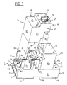
- the limiter contactor consists first of all of a switch module 1 comprising, inside of a box B1, three normally open type power switch devices, only one of which is visible in FIG. 2 and which each include: - two fixed contact elements 3, 4 carried by two conductors 5, 6 respectively connected to two connectors 7, 8; a mobile assembly comprising a mobile contact carrier 9 made of an electrically conductive material and on which are mounted two mobile contact elements 10, 11 intended to cooperate with the respective fixed contact elements 3, 4; - an operating member consisting of a pusher 12, made of an electrically insulating material, integral with the movable contact carrier 9; a spring 13 disposed between the support wall 14 of the housing 2 and the movable contact carrier 9, so as to exert a force tending to apply the movable contacts 10, 11 against the fixed contacts 3, 4.
- this switch which is shown very schematically, can also include all the equipment with which the switches are usually fitted, such as, for example, arc splitting fins, decompression channels, etc. elsewhere, the conductors 5 and 6 have a folded shape allowing the development of repulsion forces acting on the movable contact carrier 9, under the effect of the current flowing in the switch.
- the housing B1 has an elongated shape of general appearance which is substantially parallelepipedic and comprises: - two opposite parallel longitudinal faces 15, 16 which act as junction faces in the case of an assembly of several modules 1 arranged side by side; - two opposite side faces 17, 18; - A support face 19 which comprises, in its middle part, a prismatic concavity 20, of trapezoidal section, normally oriented to the longitudinal faces 15, 16, which is used for mounting the housing 2 on a profile support rail of conventional type; and - an assembly face 21 opposite the support face 19.
- This assembly face 21 has, in its middle part, a partition 22 which extends perpendicularly to the longitudinal faces 15, 16 and to the assembly face 21.
- This partition 22 separates the assembly face 21 into two zones, namely, a zone Z1 intended to receive a direct control module 23 and a zone Z2 intended to receive an indirect control module 24. It comprises, on the side of the assembly zone Z2, a stepped profile P1 and, on the side of the zone Z1, a flat face F perpendicular to the assembly face 21.
- Zone Z1 comprises, in the vicinity of the partition 22, three orifices O aligned perpendicular to the longitudinal faces 15, 16, through which the pushers 12 of the three switches pass.
- the lateral faces 17, 18 each have three orifices C1, C2, C3 for access to the connection devices 7, 8 whose clamping screws 25, 25 ′ are accessible by means of orifices Aifices, A2, A3, A′1, A′2 correspondents provided in the assembly face 21.
- the direct control device 23 comprises a housing B2 of parallelepiped shape which is fixed by its base 26 on the assembly zone Z1 slightly set back from the zone Z′1 in which the pushers 12 stand out.
- This box B2 contains an electromagnet 27 whose movable armature 28 (or the core) is connected to a lever 29 used for actuating the pushers 12 of the switches.
- the end of the lever 29 located opposite its connection to the frame 28 cooperates with a rake 30 movable in translation in the interval between the housing B2 and the partition 22 and supported by the pushers 12 of the three switches.
- the lever 29 and the rake 30 are then arranged so that the excitation of the coil of the electromagnet 27 generates a tilting of the lever 29 which causes a translational movement of the rake 30 and the three pushers 12, at the against the action exerted by the springs 13, in the direction of opening of the contacts 3, 4 - 10, 11.
- the excitation of the coil 31 of the electromagnet is ensured by means of a remote control circuit connecting to two terminals 32, 33 provided on the housing B2 and comprising a switch 34 arranged in series.
- This switch 34 is controlled by a pusher 35 accessible by an opening provided on the face 36 of the housing B2 located opposite the partition 22.
- the indirect switching control module 24 is in the form of a prismatic housing B3 of rectangular cross section having: - Two opposite longitudinal flat faces 37, 38 parallel to each other and separated from each other by a distance substantially equal to that of the longitudinal faces 15, 16 of the switch module 1; - An assembly face 39 which extends perpendicular to the longitudinal faces 37, 38 and which has a base 40 intended to come opposite the assembly zone Z2, as well as a region with a stepped profile P2 of a shape substantially complementary to that of the stepped profile Pois of the partition 22; - Two opposite parallel lateral faces 41, 42 one of which 41, which is situated on the side of the stepped profile P2, is intended to come into contact with the face 36 of the direct control module 23; and - a front face 43 having a step 44 on which is mounted a rotary reset control button 45.
- the indirect switching control module 24 comprises both a triggering device with potential accumulation and the protection devices associated with it, such as, for example, an electromagnet intended to cause the triggering of the device in response. has abrupt overcurrents or short-circuits, a thermal protection system, for example, bimetal intended to cause tripping following abnormal elevations of intensity lasting over time.
- the triggering device 46 has been represented schematically by a block into which the axis 47 of the reset control button 45 penetrates and which comprises two actuating members, namely: - A first actuating member 48 represented by a pusher, passing through an orifice provided in the stage 49 of the housing B3, at a location located at the right of the rake 30, when the module 24 is assembled to the switch module l , and a second actuating member 50 represented by a pusher, passing through an orifice provided in the lateral face 42 of the housing B3, at a location located in view of the push-button 35 of the direct switching control module 23, when the two modules 23, 24 are assembled to module 1.
- the first actuating member 48 can take two positions, namely: a retracted position which corresponds to the armed state of the trigger module (and to the "stop" and “auto” positions of the button 45), position in which this member 48 exerts no action on the rake 30 so as to allow the power switch devices of module 1 to move to their normally closed positions, and - Following a trip, a deployed position in which it presses on the rake 30 so as to keep the power switches open.
- the second actuating member 50 can also take a retracted position in which it does not stress the plunger 35 and a deployed position in which it acts on the plunger 35 so as to close the switch 34 of the control module 23, the passage from the retracted position to the deployed position being effected by passing the button 45 from the "off" position (that is to say arming) to an "auto" position.
- the triggering device 46 further comprises a triggering member 52 represented here by a pusher which, when it is pressed, causes the first actuation member 48 to pass suddenly, from its retracted position to its deployed position.
- the protection devices 53 associated with the triggering device 46 which are housed here in the indirect switching control module 24, have been represented diagrammatically by a block in FIG. 2.
- actuating member 54 represented by a pusher
- triggering member 52 following the detection of an anomaly of the current passing through the power switches of the module 1.
- the electrical connections between the current lines passing through these power switches and these protection devices 53 are established by means of three pairs of male 55 and female 56 connection elements respectively provided on the shelves 57, 58 opposite the modules 1 and 23; the male connection elements 55 are connected to the protective devices 53 by means of links 59, while the female connection elements 56 are respectively connected to the conductors 5 of the power switches.
- the male connection elements 55 are designed so as to respectively engage in the female connection elements 56 during assembly of the indirect switching control module 24 on the switch module 1.
- this assembly is ensured by bringing the module 24 onto the module 1 at the end of a translational movement perpendicular to the assembly face 21.
- the module 24 is guided by guide wings 61, 62 - 61 ′, 62 ′ which extend the longitudinal faces 15, 16 in regions adjacent to the partition 22 and to the transverse edge 63 and terminate at the level of the upper stage 64 of the partition 22.
- the attachment of the indirect switching control module 24 to the switch module 1 is ensured by means of at least one screw 65 which engages in a through passage of the housing B3 to come to be screwed (in the assembled position of the modules 1 and 24) in a tapped hole 66 provided in the step 64 of the partition 22, the axis of the screw 65 and that of the hole 66 being perpendicular to said step 64.
- the head 67 of the screw 65 engages in a well 68 produced on the stage 44 of the front face 43 in the area of rotation of the flange 69 of the cocking button 45.
- the flange 69 of the button 45 has a notch 70 arranged so as to coincide with the well 68 only when the button 45 is in the "off” position.
- the button when the button is not in the "off” position, it therefore becomes impossible to disassemble the modules 1 and 24 or, on the contrary, to assemble them.
- the guide wings 61, 61 ′ - 62, 62 ′ and the fact that the head 67 of the screw 65 is trapped in the well 68 by the flange 69 of the button 45 an attempt to assemble the two modules 1, 24 cannot lead to accidental actuation of the power switches; the module 24 will be kept away from the module 1 by the screw 65.
- the length of the portion of the screw 65 emerging from the module 24 will be provided greater than the length of the stroke of the actuating member 48, so that the latter cannot come to bear on the rake 30 during such an attempt.
- the screw 65 can be biassed axially by a spring, so that in the unscrewed position, it remains engaged in the notch 70 and thus prohibits any operation of the button 45.
- the attachment of the module 24 to the module 23 is, moreover, ensured by means of a tongue 71, integral with the housing B3, which extends parallel to the lateral face 42 from the tier 44 and which engages in a slot provided on the face 72 of the housing B2.
- This arrangement makes it possible in particular to avoid a separation of the housings B2 and B3 under the effect of the pressure exerted by the actuating member 50 on the pusher 35.
- the notch 70 of the flange 69 is in coincidence with the well 68, and the head 67 of the screw 65 is accessible, either for assembly or for disassembly.
- the actuating members 48, 50 are in the retracted state and the module 24 is in the armed state.
- This module has no action on the switch module 1 and the direct switching module 23 is inhibited due to the fact that the switch 34, which is not pressed, is in the open state.
- the triggering member 52 When the triggering member 52 is requested by the protective devices 53, it causes the actuating member 48 to pass to the deployed position, thereby causing the power switches of the module 1 to open. , the button 45 rotates 45 ° counterclockwise, position in which the flange 69 prohibits access to the head 67 of the screw 65 ( Figure 5).
- Resetting is then obtained by rotating the button 45 75 ° counterclockwise to the "arming" position shown in Figure 6, then returning the button (clockwise) to the "stop” position shown in Figure 3. The button can then be returned to the "auto” position in Figure 4.
- the device according to the invention achieves very high security, while being very simple and non-binding for the user.
Landscapes
- Switch Cases, Indication, And Locking (AREA)
- Breakers (AREA)
- Mechanisms For Operating Contacts (AREA)
- Push-Button Switches (AREA)
- Gas-Insulated Switchgears (AREA)
- Manipulator (AREA)
- Rotary Switch, Piano Key Switch, And Lever Switch (AREA)
- Driving Mechanisms And Operating Circuits Of Arc-Extinguishing High-Tension Switches (AREA)
- Aiming, Guidance, Guns With A Light Source, Armor, Camouflage, And Targets (AREA)
- Telephone Set Structure (AREA)
Applications Claiming Priority (2)
| Application Number | Priority Date | Filing Date | Title |
|---|---|---|---|
| FR8814016 | 1988-10-27 | ||
| FR8814016A FR2638563B1 (fr) | 1988-10-27 | 1988-10-27 | Dispositif de securite pour appareil de commutation realise par l'assemblage de plusieurs elements modulaires amovibles |
Publications (2)
| Publication Number | Publication Date |
|---|---|
| EP0366519A1 true EP0366519A1 (de) | 1990-05-02 |
| EP0366519B1 EP0366519B1 (de) | 1993-04-28 |
Family
ID=9371310
Family Applications (1)
| Application Number | Title | Priority Date | Filing Date |
|---|---|---|---|
| EP89402830A Expired - Lifetime EP0366519B1 (de) | 1988-10-27 | 1989-10-13 | Durch den Zusammenbau von mehreren abnehmbaren Moduleinheiten hergestellte Sicherungsvorrichtung für Schaltgerät |
Country Status (30)
| Country | Link |
|---|---|
| US (1) | US4973929A (de) |
| EP (1) | EP0366519B1 (de) |
| JP (1) | JPH02170318A (de) |
| KR (1) | KR920008838B1 (de) |
| CN (1) | CN1021525C (de) |
| AU (1) | AU620159B2 (de) |
| BG (1) | BG50949A3 (de) |
| BR (1) | BR8905499A (de) |
| CA (1) | CA2001670C (de) |
| CZ (1) | CZ279959B6 (de) |
| DD (1) | DD286455A5 (de) |
| DE (1) | DE68906238T2 (de) |
| DK (1) | DK536189A (de) |
| DZ (1) | DZ1368A1 (de) |
| EG (1) | EG19733A (de) |
| ES (1) | ES2040485T3 (de) |
| FI (1) | FI94469C (de) |
| FR (1) | FR2638563B1 (de) |
| HK (1) | HK103993A (de) |
| IE (1) | IE63610B1 (de) |
| IL (1) | IL92002A0 (de) |
| MX (1) | MX173663B (de) |
| MY (1) | MY104247A (de) |
| PT (1) | PT92101B (de) |
| RO (1) | RO106176B1 (de) |
| RU (1) | RU1836742C (de) |
| SK (1) | SK278330B6 (de) |
| TN (1) | TNSN89116A1 (de) |
| TR (1) | TR23937A (de) |
| ZA (1) | ZA898125B (de) |
Cited By (13)
| Publication number | Priority date | Publication date | Assignee | Title |
|---|---|---|---|---|
| FR2685124A1 (fr) * | 1991-12-17 | 1993-06-18 | Telemecanique | Appareil interrupteur de protection tel que contacteur-disjoncteur. |
| EP0628981A1 (de) * | 1993-06-07 | 1994-12-14 | Schneider Electric Sa | Schutzschaltgerät mit Betätigungsmechanismus |
| FR2706221A1 (fr) * | 1993-06-07 | 1994-12-16 | Telemecanique | Appareil interrupteur de protection. |
| EP0669633A1 (de) * | 1994-02-25 | 1995-08-30 | Schneider Electric Sa | Schutzschaltgerät |
| FR2756414A1 (fr) * | 1996-11-25 | 1998-05-29 | Schneider Electric Sa | Appareil interrupteur electromagnetique |
| FR2759489A1 (fr) * | 1997-02-12 | 1998-08-14 | Schneider Electric Sa | Appareil electrique multipolaire composable |
| FR2759486A1 (fr) * | 1997-02-12 | 1998-08-14 | Schneider Electric Sa | Electroaimant de commande pour appareil electrique interrupteur |
| WO2000021103A1 (de) * | 1998-10-07 | 2000-04-13 | Aeg Niederspannungstechnik Gmbh & Co. Kg. | Stromschalter |
| FR2799572A1 (fr) * | 1999-10-11 | 2001-04-13 | Schneider Electric Ind Sa | Contacteur-disjoncteur |
| FR2799574A1 (fr) * | 1999-10-11 | 2001-04-13 | Schneider Electric Ind Sa | Contacteur-disjoncteur |
| DE102006018852B3 (de) * | 2006-04-22 | 2007-09-13 | Moeller Gmbh | Handbetätigter Schutzschalter |
| EP2219199A1 (de) * | 2009-02-12 | 2010-08-18 | Eaton Industries GmbH | Schaltgerätesystem |
| FR2999791A1 (fr) * | 2012-12-18 | 2014-06-20 | Schneider Electric Ind Sas | Dispositif modulaire de commutation electrique comportant au moins un bloc de coupure unipolaire et ensemble de commutation comportant de tels dispositifs |
Families Citing this family (27)
| Publication number | Priority date | Publication date | Assignee | Title |
|---|---|---|---|---|
| SE463364B (sv) * | 1988-06-03 | 1990-11-12 | Ecocure Ab | Foerfarande foer avlaegsnande av kvaevefoereningar ur raavatten |
| IT1231103B (it) * | 1989-08-09 | 1991-11-18 | Sace Spa | Dispositivo autocoordinato di manovra e protezione per apparecchiature elettriche. |
| FR2669463B1 (fr) * | 1990-11-15 | 1995-05-12 | Telemecanique | Interrupteur de protection. |
| FR2673486B1 (fr) * | 1991-02-28 | 1996-03-01 | Telemecanique | Appareil interrupteur de courant. |
| FR2676592B1 (fr) * | 1991-05-13 | 1993-07-23 | Telemecanique | Appareil interrupteur de courant a protection thermique et magnetique. |
| US5296826A (en) * | 1993-05-13 | 1994-03-22 | Eaton Corporation | Switch assembly |
| US5634554A (en) * | 1994-12-15 | 1997-06-03 | Siemens Energy & Automation, Inc. | Interface connection for a circuit breaker plug-in trip unit |
| DE19519756C1 (de) * | 1995-05-30 | 1996-07-25 | Siemens Ag | Elektromagnetisches Schaltgerät |
| US5646586A (en) * | 1995-11-01 | 1997-07-08 | General Electric Company | Electronic trip unit conversion kit for high ampere-rated circuit breakers |
| DE29615405U1 (de) * | 1996-09-04 | 1996-10-31 | Klöckner-Moeller GmbH, 53115 Bonn | Fernantrieb für Niederspannungs-Schutzschalter |
| DE19802921A1 (de) * | 1998-01-21 | 1999-07-22 | Siemens Ag | Niederspannungs-Leistungsschalter mit einem Hilfsauslöser |
| US6150908A (en) * | 1998-09-03 | 2000-11-21 | Fuji Electric Co., Ltd. | Circuit breaker with metal melt isolation device |
| SE513442C2 (sv) * | 1999-01-28 | 2000-09-11 | Asea Brown Boveri | Kontaktor |
| US6686672B2 (en) * | 1999-09-28 | 2004-02-03 | Rockwell Automation Technologies, Inc. | Modular emergency stop relay system |
| CN1253912C (zh) * | 2003-05-29 | 2006-04-26 | 刘平 | 电力开关器 |
| ATE486363T1 (de) * | 2005-06-20 | 2010-11-15 | Siemens Ag | Modulares schaltgerät |
| JP5396149B2 (ja) * | 2009-05-20 | 2014-01-22 | 株式会社マキタ | 動力工具 |
| WO2011069536A1 (en) * | 2009-12-08 | 2011-06-16 | Abb Ab | A contactor |
| EP2549515A1 (de) * | 2011-07-21 | 2013-01-23 | Eaton Industries GmbH | Schalteranordnung zum Herstellen und/oder Trennen einer Verbindung eines Steckers mit einem Gegenstecker |
| FR2999781B1 (fr) * | 2012-12-18 | 2015-01-02 | Schneider Electric Ind Sas | Dispositif modulaire de commutation electrique comportant au moins un bloc de coupure unipolaire et ensemble de commutation comportant de tels dispositifs. |
| CN105070603A (zh) * | 2012-12-31 | 2015-11-18 | 胡小青 | 节省空间的智能断路器 |
| RU2643161C2 (ru) * | 2013-10-15 | 2018-01-31 | Абб Текнолоджи Лтд | Система контрольного устройства и ограничителя перенаряжения |
| JP6414453B2 (ja) | 2014-12-05 | 2018-10-31 | オムロン株式会社 | 電磁継電器 |
| JP2016110843A (ja) | 2014-12-05 | 2016-06-20 | オムロン株式会社 | 電磁継電器 |
| CN106716588B (zh) * | 2014-12-05 | 2020-01-21 | 欧姆龙株式会社 | 电磁继电器 |
| US10134551B2 (en) * | 2016-09-21 | 2018-11-20 | Astronics Advanced Electronic Systems Corp. | Galvanically isolated hybrid contactor |
| DE202023105170U1 (de) * | 2023-09-08 | 2024-12-10 | Natus GmbH & Co.KG Elektrotechnische Spezialfabrik für Industrie- Schaltanlagen-Systeme | Schaltgerätekombination |
Citations (3)
| Publication number | Priority date | Publication date | Assignee | Title |
|---|---|---|---|---|
| GB808628A (en) * | 1956-03-05 | 1959-02-11 | Revo Electric Company Ltd | Electric switches having interlocked covers |
| EP0179677A1 (de) * | 1984-09-27 | 1986-04-30 | Telemecanique | Schaltvorrichtung mit variabler Zusammensetzung |
| EP0274624A1 (de) * | 1986-12-13 | 1988-07-20 | Moeller GmbH | Handbetätigter Schutzschalter |
Family Cites Families (6)
| Publication number | Priority date | Publication date | Assignee | Title |
|---|---|---|---|---|
| FR2570871B1 (fr) * | 1984-09-27 | 1986-12-05 | Telemecanique Electrique | Dispositif de commutation a composition variable realisable par assemblage d'elements modulaires |
| FR2598027B1 (fr) * | 1986-04-23 | 1990-10-12 | Telemecanique Electrique | Appareil contacteur inverseur protege conte les surintensites de courant |
| US4875287A (en) * | 1986-11-14 | 1989-10-24 | Hydromer, Inc. | Shaving articles lubricious when wet and compositions therefor |
| US4872263A (en) * | 1988-09-30 | 1989-10-10 | The Kendall Company | Lubricating device |
| US5113585A (en) * | 1990-09-28 | 1992-05-19 | The Gillette Company | Shaving system |
| US5063667A (en) * | 1990-09-28 | 1991-11-12 | The Gillette Company | Shaving system |
-
1988
- 1988-10-27 FR FR8814016A patent/FR2638563B1/fr not_active Expired - Lifetime
-
1989
- 1989-01-26 ZA ZA898125A patent/ZA898125B/xx unknown
- 1989-10-13 EP EP89402830A patent/EP0366519B1/de not_active Expired - Lifetime
- 1989-10-13 ES ES198989402830T patent/ES2040485T3/es not_active Expired - Lifetime
- 1989-10-13 DE DE8989402830T patent/DE68906238T2/de not_active Expired - Fee Related
- 1989-10-16 IE IE332689A patent/IE63610B1/en not_active IP Right Cessation
- 1989-10-16 IL IL92002A patent/IL92002A0/xx unknown
- 1989-10-17 AU AU42938/89A patent/AU620159B2/en not_active Ceased
- 1989-10-19 MY MYPI89001455A patent/MY104247A/en unknown
- 1989-10-25 PT PT92101A patent/PT92101B/pt not_active IP Right Cessation
- 1989-10-25 DZ DZ890164A patent/DZ1368A1/fr active
- 1989-10-25 RO RO142125A patent/RO106176B1/ro unknown
- 1989-10-25 MX MX018107A patent/MX173663B/es unknown
- 1989-10-25 DD DD89333899A patent/DD286455A5/de not_active IP Right Cessation
- 1989-10-26 SK SK6058-89A patent/SK278330B6/sk unknown
- 1989-10-26 FI FI895083A patent/FI94469C/fi not_active IP Right Cessation
- 1989-10-26 EG EG51189A patent/EG19733A/xx active
- 1989-10-26 BG BG090144A patent/BG50949A3/bg unknown
- 1989-10-26 RU SU894742284A patent/RU1836742C/ru active
- 1989-10-26 US US07/426,910 patent/US4973929A/en not_active Expired - Fee Related
- 1989-10-26 CZ CS896058A patent/CZ279959B6/cs unknown
- 1989-10-27 DK DK536189A patent/DK536189A/da not_active Application Discontinuation
- 1989-10-27 CA CA002001670A patent/CA2001670C/fr not_active Expired - Fee Related
- 1989-10-27 KR KR1019890015546A patent/KR920008838B1/ko not_active Expired
- 1989-10-27 TR TR89/0794A patent/TR23937A/xx unknown
- 1989-10-27 TN TNTNSN89116A patent/TNSN89116A1/fr unknown
- 1989-10-27 JP JP1281563A patent/JPH02170318A/ja active Pending
- 1989-10-27 CN CN89108203A patent/CN1021525C/zh not_active Expired - Fee Related
- 1989-10-27 BR BR898905499A patent/BR8905499A/pt not_active IP Right Cessation
-
1993
- 1993-09-30 HK HK1039/93A patent/HK103993A/xx not_active IP Right Cessation
Patent Citations (3)
| Publication number | Priority date | Publication date | Assignee | Title |
|---|---|---|---|---|
| GB808628A (en) * | 1956-03-05 | 1959-02-11 | Revo Electric Company Ltd | Electric switches having interlocked covers |
| EP0179677A1 (de) * | 1984-09-27 | 1986-04-30 | Telemecanique | Schaltvorrichtung mit variabler Zusammensetzung |
| EP0274624A1 (de) * | 1986-12-13 | 1988-07-20 | Moeller GmbH | Handbetätigter Schutzschalter |
Cited By (27)
| Publication number | Priority date | Publication date | Assignee | Title |
|---|---|---|---|---|
| FR2685124A1 (fr) * | 1991-12-17 | 1993-06-18 | Telemecanique | Appareil interrupteur de protection tel que contacteur-disjoncteur. |
| EP0547928A1 (de) * | 1991-12-17 | 1993-06-23 | Telemecanique | Schutzschalter |
| US5293521A (en) * | 1991-12-17 | 1994-03-08 | Telemecanique | Protective relay switch having trap door |
| EP0628981A1 (de) * | 1993-06-07 | 1994-12-14 | Schneider Electric Sa | Schutzschaltgerät mit Betätigungsmechanismus |
| FR2706220A1 (fr) * | 1993-06-07 | 1994-12-16 | Telemecanique | Appareil interrupteur de protection à mécanisme de commande. |
| FR2706221A1 (fr) * | 1993-06-07 | 1994-12-16 | Telemecanique | Appareil interrupteur de protection. |
| US5502426A (en) * | 1993-06-07 | 1996-03-26 | Schneider Electric Sa | Protection switch device |
| EP0669633A1 (de) * | 1994-02-25 | 1995-08-30 | Schneider Electric Sa | Schutzschaltgerät |
| US5594399A (en) * | 1994-02-25 | 1997-01-14 | Schneider Electric Sa | Protective switching device |
| FR2756414A1 (fr) * | 1996-11-25 | 1998-05-29 | Schneider Electric Sa | Appareil interrupteur electromagnetique |
| FR2759489A1 (fr) * | 1997-02-12 | 1998-08-14 | Schneider Electric Sa | Appareil electrique multipolaire composable |
| FR2759486A1 (fr) * | 1997-02-12 | 1998-08-14 | Schneider Electric Sa | Electroaimant de commande pour appareil electrique interrupteur |
| WO2000021103A1 (de) * | 1998-10-07 | 2000-04-13 | Aeg Niederspannungstechnik Gmbh & Co. Kg. | Stromschalter |
| FR2799572A1 (fr) * | 1999-10-11 | 2001-04-13 | Schneider Electric Ind Sa | Contacteur-disjoncteur |
| FR2799574A1 (fr) * | 1999-10-11 | 2001-04-13 | Schneider Electric Ind Sa | Contacteur-disjoncteur |
| WO2001027958A1 (fr) * | 1999-10-11 | 2001-04-19 | Schneider Electric Industries S.A. | Contacteur-disjoncteur |
| AU763566B2 (en) * | 1999-10-11 | 2003-07-24 | Schneider Electric Industries Sas | Reverse current relay |
| DE10050081B4 (de) * | 1999-10-11 | 2021-02-25 | Schneider Electric Industries S.A. | Schaltschütz |
| EP1848020A3 (de) * | 2006-04-22 | 2008-06-04 | Moeller GmbH | Handbetätigter Schutzschalter |
| DE102006018852B8 (de) * | 2006-04-22 | 2008-04-17 | Moeller Gmbh | Handbetätigter Schutzschalter |
| DE102006018852B3 (de) * | 2006-04-22 | 2007-09-13 | Moeller Gmbh | Handbetätigter Schutzschalter |
| EP2219199A1 (de) * | 2009-02-12 | 2010-08-18 | Eaton Industries GmbH | Schaltgerätesystem |
| FR2999791A1 (fr) * | 2012-12-18 | 2014-06-20 | Schneider Electric Ind Sas | Dispositif modulaire de commutation electrique comportant au moins un bloc de coupure unipolaire et ensemble de commutation comportant de tels dispositifs |
| WO2014096579A1 (fr) * | 2012-12-18 | 2014-06-26 | Schneider Electric Industries Sas | Dispositif modulaire de commutation électrique comportant au moins un bloc de coupure unipolaire et ensemble de commutation comportant de tels dispositifs |
| CN104885181A (zh) * | 2012-12-18 | 2015-09-02 | 施耐德电器工业公司 | 包括至少一个单极切断单元的模块化电气开关装置以及包括这种装置的开关组件 |
| US9583292B2 (en) | 2012-12-18 | 2017-02-28 | Schneider Electric Industries Sas | Modular electrical switch device comprising at least one unipolar cut-off unit and a switch assembly comprising such devices |
| CN104885181B (zh) * | 2012-12-18 | 2017-07-07 | 施耐德电器工业公司 | 包括至少一个单极切断单元的模块化电气开关装置以及包括这种装置的开关组件 |
Also Published As
Similar Documents
| Publication | Publication Date | Title |
|---|---|---|
| EP0366519B1 (de) | Durch den Zusammenbau von mehreren abnehmbaren Moduleinheiten hergestellte Sicherungsvorrichtung für Schaltgerät | |
| EP0619591B1 (de) | Magnetothermische Auslöseeinheit | |
| EP0309311A1 (de) | Überstromschalter | |
| CA1239691A (fr) | Dispositif de commutation a composition variable realisable par assemblage d'elements modulaires | |
| EP0179677B1 (de) | Schaltvorrichtung mit variabler Zusammensetzung | |
| EP0486389B1 (de) | Schutzschalter | |
| FR2538161A1 (fr) | Disjoncteur a mecanisme electromagnetique perfectionne de declenchement a minimum de tension | |
| EP0042778A1 (de) | Einpol- und Nulleiter-Kleinschalter | |
| EP4064317B1 (de) | Elektrische schutzvorrichtung und elektrische schalttafel mit einer solchen schutzvorrichtung | |
| FR2818434A1 (fr) | Appareil de coupure electrique pour installation electrique | |
| CH686853A5 (fr) | Appareil interrupteur de protection accouplable à un module de commande et/ou à un module de signalisation. | |
| EP3159906B1 (de) | Elektrische schaltvorrichtung mit einem schaltmechanismus und mindestens einem zusatzmodul | |
| EP2743958B1 (de) | Elektrisches Stromschaltgerät, insbesondere Abzweigschalter | |
| EP2743959B1 (de) | Thermische Auslösvorrichtung und Schutzschalter mit dieser Vorrichtung | |
| FR2621418A1 (fr) | Interrupteur de protection a ecran de coupure d'arc | |
| EP0105816B1 (de) | Gerät zur automatischen Erdung einer zufällig unter Spannung stehenden Struktur | |
| EP0054499B1 (de) | Schalter mit Trennung des Nulleiters | |
| EP0736945B1 (de) | Trenner-Begrenzungs-Schutz für dreiphasige elektrische Transformatoren | |
| EP0602024B1 (de) | Betätigungsmechanismus für einen mehrpoligen Fehlerstromschutzschalter mit drehbarer Schaltwelle | |
| EP2743947A1 (de) | Kontaktarme tragende Schaltwelle in einem Schaltgerät, und damit versehenes Schaltgerät, insbesondere ein Abzweigschalter | |
| EP2889893A1 (de) | Elektrogerät in Modulformat | |
| FR2639146A1 (fr) | Appareil de commutation du type comprenant un module principal de commutation et un module de contacts auxiliaires amovible | |
| EP0218497A1 (de) | Schutzschalter mit federnder Lasche | |
| FR3057389A1 (fr) | Appareillage de coupure electrique differentiel comportant un dispositif de test de la fonction differentielle | |
| EP2743956B1 (de) | Gerät zur Stromunterbrechung, insbesondere Anschluss-Überlastschalter |
Legal Events
| Date | Code | Title | Description |
|---|---|---|---|
| PUAI | Public reference made under article 153(3) epc to a published international application that has entered the european phase |
Free format text: ORIGINAL CODE: 0009012 |
|
| 17P | Request for examination filed |
Effective date: 19891017 |
|
| AK | Designated contracting states |
Kind code of ref document: A1 Designated state(s): CH DE ES GB IT LI SE |
|
| 17Q | First examination report despatched |
Effective date: 19920918 |
|
| GRAA | (expected) grant |
Free format text: ORIGINAL CODE: 0009210 |
|
| AK | Designated contracting states |
Kind code of ref document: B1 Designated state(s): CH DE ES GB IT LI SE |
|
| ITF | It: translation for a ep patent filed | ||
| GBT | Gb: translation of ep patent filed (gb section 77(6)(a)/1977) |
Effective date: 19930504 |
|
| REF | Corresponds to: |
Ref document number: 68906238 Country of ref document: DE Date of ref document: 19930603 |
|
| REG | Reference to a national code |
Ref country code: ES Ref legal event code: FG2A Ref document number: 2040485 Country of ref document: ES Kind code of ref document: T3 |
|
| PLBE | No opposition filed within time limit |
Free format text: ORIGINAL CODE: 0009261 |
|
| STAA | Information on the status of an ep patent application or granted ep patent |
Free format text: STATUS: NO OPPOSITION FILED WITHIN TIME LIMIT |
|
| 26N | No opposition filed | ||
| EAL | Se: european patent in force in sweden |
Ref document number: 89402830.7 |
|
| PGFP | Annual fee paid to national office [announced via postgrant information from national office to epo] |
Ref country code: CH Payment date: 19981020 Year of fee payment: 10 |
|
| PGFP | Annual fee paid to national office [announced via postgrant information from national office to epo] |
Ref country code: SE Payment date: 19981021 Year of fee payment: 10 |
|
| PGFP | Annual fee paid to national office [announced via postgrant information from national office to epo] |
Ref country code: ES Payment date: 19991015 Year of fee payment: 11 |
|
| PG25 | Lapsed in a contracting state [announced via postgrant information from national office to epo] |
Ref country code: SE Free format text: THE PATENT HAS BEEN ANNULLED BY A DECISION OF A NATIONAL AUTHORITY Effective date: 19991030 |
|
| PG25 | Lapsed in a contracting state [announced via postgrant information from national office to epo] |
Ref country code: LI Free format text: LAPSE BECAUSE OF NON-PAYMENT OF DUE FEES Effective date: 19991031 Ref country code: CH Free format text: LAPSE BECAUSE OF NON-PAYMENT OF DUE FEES Effective date: 19991031 |
|
| REG | Reference to a national code |
Ref country code: CH Ref legal event code: PL |
|
| EUG | Se: european patent has lapsed |
Ref document number: 89402830.7 |
|
| PGFP | Annual fee paid to national office [announced via postgrant information from national office to epo] |
Ref country code: GB Payment date: 20001006 Year of fee payment: 12 |
|
| PG25 | Lapsed in a contracting state [announced via postgrant information from national office to epo] |
Ref country code: ES Free format text: LAPSE BECAUSE OF NON-PAYMENT OF DUE FEES Effective date: 20001014 |
|
| PGFP | Annual fee paid to national office [announced via postgrant information from national office to epo] |
Ref country code: DE Payment date: 20001014 Year of fee payment: 12 |
|
| PG25 | Lapsed in a contracting state [announced via postgrant information from national office to epo] |
Ref country code: GB Free format text: LAPSE BECAUSE OF NON-PAYMENT OF DUE FEES Effective date: 20011013 |
|
| REG | Reference to a national code |
Ref country code: GB Ref legal event code: 732E |
|
| REG | Reference to a national code |
Ref country code: GB Ref legal event code: IF02 |
|
| GBPC | Gb: european patent ceased through non-payment of renewal fee |
Effective date: 20011013 |
|
| PG25 | Lapsed in a contracting state [announced via postgrant information from national office to epo] |
Ref country code: DE Free format text: LAPSE BECAUSE OF NON-PAYMENT OF DUE FEES Effective date: 20020702 |
|
| REG | Reference to a national code |
Ref country code: ES Ref legal event code: FD2A Effective date: 20011113 |
|
| PG25 | Lapsed in a contracting state [announced via postgrant information from national office to epo] |
Ref country code: IT Free format text: LAPSE BECAUSE OF NON-PAYMENT OF DUE FEES;WARNING: LAPSES OF ITALIAN PATENTS WITH EFFECTIVE DATE BEFORE 2007 MAY HAVE OCCURRED AT ANY TIME BEFORE 2007. THE CORRECT EFFECTIVE DATE MAY BE DIFFERENT FROM THE ONE RECORDED. Effective date: 20051013 |