EP0366546A1 - Sockel für Elektrogeräte, insbesondere Alarmzentrale und entsprechende Elektrogeräte - Google Patents
Sockel für Elektrogeräte, insbesondere Alarmzentrale und entsprechende Elektrogeräte Download PDFInfo
- Publication number
- EP0366546A1 EP0366546A1 EP89402945A EP89402945A EP0366546A1 EP 0366546 A1 EP0366546 A1 EP 0366546A1 EP 89402945 A EP89402945 A EP 89402945A EP 89402945 A EP89402945 A EP 89402945A EP 0366546 A1 EP0366546 A1 EP 0366546A1
- Authority
- EP
- European Patent Office
- Prior art keywords
- sole
- present
- compartment
- front face
- clearance
- Prior art date
- Legal status (The legal status is an assumption and is not a legal conclusion. Google has not performed a legal analysis and makes no representation as to the accuracy of the status listed.)
- Granted
Links
- 230000002093 peripheral effect Effects 0.000 claims abstract description 19
- 241001272720 Medialuna californiensis Species 0.000 claims description 2
- 239000004020 conductor Substances 0.000 description 29
- 238000001514 detection method Methods 0.000 description 4
- 238000000926 separation method Methods 0.000 description 4
- 230000015556 catabolic process Effects 0.000 description 3
- 238000000034 method Methods 0.000 description 3
- 238000003745 diagnosis Methods 0.000 description 1
- 238000009434 installation Methods 0.000 description 1
- 238000002955 isolation Methods 0.000 description 1
- 238000012423 maintenance Methods 0.000 description 1
- 230000014759 maintenance of location Effects 0.000 description 1
- 210000000056 organ Anatomy 0.000 description 1
- 230000004224 protection Effects 0.000 description 1
- 230000001681 protective effect Effects 0.000 description 1
Images

Classifications
-
- H—ELECTRICITY
- H05—ELECTRIC TECHNIQUES NOT OTHERWISE PROVIDED FOR
- H05K—PRINTED CIRCUITS; CASINGS OR CONSTRUCTIONAL DETAILS OF ELECTRIC APPARATUS; MANUFACTURE OF ASSEMBLAGES OF ELECTRICAL COMPONENTS
- H05K5/00—Casings, cabinets or drawers for electric apparatus
Definitions
- the present invention relates generally to electrical apparatus of the kind comprising, attached to a base itself to be fixed on any support, a plurality of components, possibly grouped into functional blocks, with, most often, covering the whole , a lid.
- alarm control panels whether they are intrusion alarm control panels, fire alarm control panels, or alarm control panels combining both of the two corresponding protections.
- alarm centers in fact comprise, on the one hand, a supply circuit, to which it is advisable to wire specific conductors for their high current supply, and, on the other hand, detection circuits, to which it on the contrary, it is advisable to wire conductors which, carrying low current, are intended to allow their connection to various detection, control or alarm organs, scattered around.
- the present invention generally relates to a provision making it possible to satisfy this requirement and further leading to other benefits.
- a base for electrical equipment in particular an alarm center, of the type comprising a sole suitable for its application against any support and for its attachment thereto, this base being generally characterized in that, inside its periphery, said sole extends according to at least two different levels, so that, on its rear face, it forms a clearance, in that, on its front face, it carries, set back with respect to its periphery, over at least part of the length thereof, wall elements which, projecting from this front face, delimit there at least in part, at least a compartment, with at least one passage by which said clearance communicates with such a compartment, and, more precisely, with the central volume inside it, and in that it presents, on at least one of its sides , between said wall elements and its p around, at least one opening through which said clearance communicates furthermore with the peripheral volume outside said compartment; it also relates to electrical equipment, in particular an alarm center, comprising such a base.
- the clearance present on the rear face of the base of the base according to the invention is intended for the routing of conductors carrying high current, while the peripheral volume present on its front face is intended for the routing of conductors carrying low current .
- the invention is reinforced by the fact that, in the clearance formed by the sole on its rear face, is arranged, for the routing of conductors carrying strong current, a flexible tube, which extends from the passage making communicate this clearance with a compartment present on the front face of the sole, and which crosses this one thanks to one of its openings.
- the housing in question advantageously allows the slack of these conductors to be swallowed after their connection to the connection terminal provided for them, they are thus, in service, completely covered by a functional block, including their connection end at this connection terminal, which isolates them even more surely from the rest of the assembly.
- the sole of the base according to the invention having an aperture on each of its sides, the various conductors concerned, whether they are conductors carrying strong current or whether they are conductors carrying current weak, can advantageously arrive, indifferently, in favor of such an aperture, on any one of these sides, which makes the wiring of the corresponding electrical equipment particularly easy.
- this wiring is further facilitated, according to a development of the invention, by the fact that, in the electrical equipment concerned, the corresponding terminal blocks are arranged at the edge of the peripheral volume present on the front face of the base of the base according to the invention, and that, thanks to this peripheral volume, which somehow forms, around the assembly, a corridor giving access to these terminal blocks, they can walk towards them whatever the side of this base by which they arrive.
- compartments on the front face of the base favors an additional arrangement according to which the components presenting no risk of failure are reported on a base card permanently fixed to this base while those presenting risks of breakdown are divided into functional blocks removably reported on this base card.
- the arrangement according to the invention makes it possible to ensure an effective dielectric separation, between the currents of different natures arriving at the electrical equipment concerned, it makes the wiring of this electrical equipment easy, and it facilitates maintenance thereof.
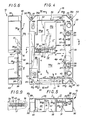
- this central alarm unit comprises, overall, a base 10, by which it is intended to be attached to any support, for example a wall, and, themselves attached to this base 10, according to arrangements briefly described below, a plurality of functional components, with, covering the whole, being detachably secured to the base 10 by screws 11, a cover 12.
- those of these functional components which are not liable to breakdown are preferably grouped together on a base card 13, intended to be permanently attached to the base 10, and that those which are on the contrary susceptible to breakdowns are grouped into functional blocks, which here are two in number, namely a power supply 14A and a management block 14B, are adapted to be removably attached to the base card 13.
- a battery 14C intended to be directly attached to the base 10, away from the card base 13.
- the cover 12 includes a window 16 possibly closed by a protective flap.
- the service of the alarm center thus constituted requires, on the one hand, for its supply, electrical conductors 17, suitable for its connection to any source of strong current supply, for example the sector, and, on the other hand, for its connection to external detection members, and as shown diagrammatically in broken lines for two of them in FIG. 4, electrical conductors 18 carrying them, of low current.
- connection terminal 19 carried by the base card 13 and, likewise, the electrical conductors 18 are connected by terminal blocks 20, FIG. 1, them also worn by it.
- the base 10 which is more particularly the object of the present invention, comprises a sole 22 suitable for its application against the support to be fitted and for its attachment thereto.
- this sole 22 has a rectangular outline.
- the holes 24A which are two in number, being arranged along the same longitudinal edge, are here keyhole buttonholes, one elongated in one direction, the other elongated in the direction perpendicular to the previous one .
- the holes 24B which are also two in number, being arranged along the longitudinal edge opposite to the previous one, here consist of simple circular contour holes, and there are associated with them washers 25, which, molded in one piece with the assembly, are suitable for being mounted, once detached from such an assembly, in these holes 24B, according to any angular orientation relative to the axis thereof, and which have each a single buttonhole 26.
- the sole 22 of the base 10 according to the invention extends, inside its periphery, along at least two different levels I, II, so that, on its rear face, that by which it is intended to be applied to the support to be fitted, it forms a clearance 28.
- this clearance 28 has, overall, in plan, an L-shaped contour, parallel to the edges of the sole 22, and with a bar of this contour clearly wider than the other.
- the sole 22 of the base 10 carries, on its front face, set back relative to its periphery, wall elements 30, which, projecting from this front face, delimit there, at least in part, and according to methods described in more detail later, at least one compartment 31, 32, with, outside such a compartment 31, 32, between said wall elements 30 and its periphery, a peripheral volume 33.
- the wall elements 30, which it is not necessary to describe in detail here, all have, overall, the same height, and they delimit, on the front face of the sole 22, two compartments 31, 32.
- the first, compartment 31 is intended for housing the base card 13, and, with the latter, for that of the functional blocks 14A, 14B.
- the second compartment, compartment 32 is intended for the housing of the battery 14C.
- plan it has, overall, a rectangular outline, and this outline is nested in that of compartment 31, the assembly repeating, at a distance, the outline of sole 22.
- the compartment 31 is at least partially open on at least one of its sides, at the edge of the peripheral volume 33 outside the assembly.
- this compartment 31 is thus open on all of one of its sides, that corresponding to the largest bar of its L-shaped outline, parallel to a longitudinal edge of the sole 22, and it is bordered, along this side, by a strip 34, having, from place to place, elongated openings 37, at the rate of one per terminal block 20.
- transverse edges of these openings 37 are slightly oblique, converging towards one another, FIG. 7.
- the strip 34 also has, from place to place, in the direction of compartment 31, projections 45 under which the base card 13 must be slid.
- the compartments 31, 32 communicate with each other.
- wall elements 30 which, forming a border between these compartments 31, 32, extend in split with respect to wall elements 30 jointly forming a longitudinal edge for these, provide a gap between them and the latter 35.
- a passage 36 through which the clearance 28 present on the rear face of the sole 22 communicates with a compartment 31, 32 present on its front face, and, more precisely, with the central volume inside this compartment 31, 32, and, jointly, this sole 22 has, on at least one of its sides, between the wall elements 30 and its periphery, at least one aperture 38 by which said clearance 28 furthermore communicates with the peripheral volume 33 outside this compartment 31, 32.
- the sole 22 has an opening 38 on each of these sides, and such an opening 38 is bordered, in part, by a portion 39 I , of first level I of this sole 22, and , in part, by a portion 39 II , of second level II, of the latter, so that it is thanks to the offset between these portions 39 I , 39 II , of levels I, II different that this opening 38 communicates the clearance 28 present on the rear face of the sole 22 with the peripheral volume 33 present on its front face.
- the sole 22 mainly extends only along two levels, namely, on the one hand, the first level I, which corresponds to that of its rear face, and to which the various portions belong 39 I which it comprises, and, on the other hand, the second level II, which, set back from the previous one, is also set back from its periphery, and to which its portions 39 II belong.
- the sole 22 s' extends along another intermediate level between the first two levels I, II.
- compartment 32 the bottom of which is formed in part by a portion 39 I of first level I of the sole 22, and, in part, by a portion 39 III of level III of this sole 22 slightly behind compared to the previous one.
- a housing 40 is formed by a portion 39 IV of level IV of the sole 22 recessed with respect to its portion 39 III of level III, between the latter and its portions 39 II of level II.
- the bottom of the compartment 31 is formed by a portion 39 II of level II of the sole 22.
- the passage 36 opens into this housing 40, and, through the latter, into the compartment 31, that open on one side.
- this passage 36 is formed by means of a connecting wall 42 intermediate between two portions of different levels of the sole 22, in this case a portion 39 II of level II and a portion 39 IV level IV.
- This connecting wall 42 extends substantially perpendicularly to the portions 39 III , 39 IV of different levels III, IV which it connects, parallel to the transverse edges of the sole 22.
- the housing 40 which, on the other side, is bordered by the wall elements 30 separating the compartments 31, 32, is bordered by a rim 43 slightly projecting from the corresponding portion 39 II , level II, from sole 22.
- the wall elements 30 separating the compartments 31, 32 are affected, to their base, by a slot 44, which, like the slot 35 previously described, makes these compartments 31, 32 communicate with each other, but which, markedly wider than this slot 35, is intended, for its part, and according to the methods described later, to be concealed in service.
- the passage 36 is in a half-moon shape, and, on the rear face of the sole 22 of the base 10, there is associated with it a flange 46, which, completing it, is suitable for allowing securing.
- a flexible tube 48 intended to serve as a housing for the electrical conductors 17.
- This flexible tube 48 which, as shown, over a section of its length, in Figure 3, is, for example, a corrugated tube, therefore extends from the passage 36, and, disposed in the clearance 28 that the sole 22 forms on its rear face, it passes through this sole 22 in favor of any of its openings 38.
- these additional wall elements 50 have a cutaway leaving the wells 23 outside the peripheral volume 33.
- the wells 23 protrude over a portion 39 I of level I of the sole 22 while the holes 24A, 24B are formed on a portion 39 II of level II thereof.
- the base 10 thus formed is associated with jumpers 52, at the rate of one opening 37 in the strip 34.
- the base 10 according to the invention is only equipped with the single base card 13.
- This base card 13 is attached to the bottom of its compartment 31.
- terminal blocks 20 As already indicated, it carries, in addition to other components, terminal blocks 20.
- these terminal blocks 20 are arranged on the edge of this base card 13, on the open side of the compartment 31.
- the flexible tube 48 intended for housing these conductors 17 penetrates, laterally, in the clearance 28 present on the rear face of the sole 22, on one or the other of the sides thereof, by means of the corresponding aperture 38 of this sole 22.
- connection terminal 19 When wiring, they are connected to the connection terminal 19 carried by the base card 13, the arrangements being such that this connection terminal 19 extends at the edge of the housing 40, along one of the transverse sides of that -this, in the immediate vicinity of passage 36.
- the conductors 18 can arrive by any side of the sole 22 of the base 10 according to the invention, either, laterally, as shown schematically in broken lines in Figure 4, either from below.
- terminal blocks 20 are connected, at their end, to terminal blocks 20.
- the conductors 18 are thus advantageously held, by wedging, in position.
- the wiring, thus made, of the conductors 18, can intervene before or after the installation of the functional blocks 14A, 14B and that of the battery 14C.
- the functional block 14A which is the power supply unit, and which is removable, covers, on the one hand, the housing 40 through which the passage 36 opens, and, on the other hand, the terminal of connection 19 arranged on the edge of this housing 40.
- the casing of this functional block 14A has, projecting from its rear face, a tab 55, which, provided at right of passage 36, obscures the slot 44 of the wall elements 30 separating the compartments 31, 32 from one another, thereby isolating, from this instant, these two compartments 31, 32 from one another.
- the routing of the electrical conductors necessary for the service of the 14C battery by the block functional 14A is in fact made by means of the slot 35 otherwise provided between the corresponding wall elements 30.
- a micro-switch suitable for triggering an alarm can be provided in the event of the cover 11 being torn off vis-à-vis the base 10, and / or a tearing of this base 10 vis-à-vis the support on which it is attached.
- the base according to the invention may possibly also be suitable for other electrical equipment, and, for example, for a telephone transmitter.
Landscapes
- Engineering & Computer Science (AREA)
- Microelectronics & Electronic Packaging (AREA)
- Emergency Alarm Devices (AREA)
- Burglar Alarm Systems (AREA)
- Switch Cases, Indication, And Locking (AREA)
- Battery Mounting, Suspending (AREA)
Applications Claiming Priority (2)
| Application Number | Priority Date | Filing Date | Title |
|---|---|---|---|
| FR8814047 | 1988-10-27 | ||
| FR8814047A FR2638595B1 (fr) | 1988-10-27 | 1988-10-27 | Socle pour appareillage electrique, notamment centrale d'alarme, et appareillage electrique correspondant |
Publications (2)
| Publication Number | Publication Date |
|---|---|
| EP0366546A1 true EP0366546A1 (de) | 1990-05-02 |
| EP0366546B1 EP0366546B1 (de) | 1993-06-16 |
Family
ID=9371332
Family Applications (1)
| Application Number | Title | Priority Date | Filing Date |
|---|---|---|---|
| EP19890402945 Expired - Lifetime EP0366546B1 (de) | 1988-10-27 | 1989-10-25 | Sockel für Elektrogeräte, insbesondere Alarmzentrale und entsprechende Elektrogeräte |
Country Status (4)
| Country | Link |
|---|---|
| EP (1) | EP0366546B1 (de) |
| DE (1) | DE68907179T2 (de) |
| ES (1) | ES2041431T3 (de) |
| FR (1) | FR2638595B1 (de) |
Families Citing this family (1)
| Publication number | Priority date | Publication date | Assignee | Title |
|---|---|---|---|---|
| DE29513555U1 (de) * | 1995-08-23 | 1995-10-26 | Siemens AG, 80333 München | Betätigungsstation der Gebäudesystemtechnik |
Citations (3)
| Publication number | Priority date | Publication date | Assignee | Title |
|---|---|---|---|---|
| FR1348392A (fr) * | 1964-04-06 | Perfectionnements aux dispositifs de sécurités et d'alertes | ||
| WO1982001953A1 (fr) * | 1980-11-27 | 1982-06-10 | Lechner Heinz | Appareil de surveillance |
| GB2126016A (en) * | 1982-08-31 | 1984-03-14 | Lero Engineering Limited | Electrical control unit |
-
1988
- 1988-10-27 FR FR8814047A patent/FR2638595B1/fr not_active Expired - Fee Related
-
1989
- 1989-10-25 DE DE1989607179 patent/DE68907179T2/de not_active Expired - Fee Related
- 1989-10-25 EP EP19890402945 patent/EP0366546B1/de not_active Expired - Lifetime
- 1989-10-25 ES ES89402945T patent/ES2041431T3/es not_active Expired - Lifetime
Patent Citations (3)
| Publication number | Priority date | Publication date | Assignee | Title |
|---|---|---|---|---|
| FR1348392A (fr) * | 1964-04-06 | Perfectionnements aux dispositifs de sécurités et d'alertes | ||
| WO1982001953A1 (fr) * | 1980-11-27 | 1982-06-10 | Lechner Heinz | Appareil de surveillance |
| GB2126016A (en) * | 1982-08-31 | 1984-03-14 | Lero Engineering Limited | Electrical control unit |
Also Published As
| Publication number | Publication date |
|---|---|
| FR2638595A1 (fr) | 1990-05-04 |
| EP0366546B1 (de) | 1993-06-16 |
| ES2041431T3 (es) | 1993-11-16 |
| FR2638595B1 (fr) | 1991-01-25 |
| DE68907179T2 (de) | 1993-09-23 |
| DE68907179D1 (de) | 1993-07-22 |
Similar Documents
| Publication | Publication Date | Title |
|---|---|---|
| EP1119088B1 (de) | Elektrische Mehrfachkammerkabelführung mit hohem Verdrahtungsvermögen | |
| EP1675236B1 (de) | Halterung für ein elektrisches Gerät | |
| EP0366546B1 (de) | Sockel für Elektrogeräte, insbesondere Alarmzentrale und entsprechende Elektrogeräte | |
| EP1675240B1 (de) | Halterung für mehrere elektrische Geräte mit indexierten Montage von elektrischen Gerätesockel | |
| EP1675235B1 (de) | Vielfacher Gerätehalter zur horizontalen und vertikalen Montage. | |
| EP0509853B1 (de) | Vorrichtung und Verriegeleinheit für Anschlussklemmen und Sammelschiene von Modularen elektrischen Geräten | |
| EP1107363B1 (de) | Monopolarer Modularerverteiler | |
| EP0729167B1 (de) | Modulares elektrisches Gerät mit eine Aussparung in eine Seitenfläche | |
| EP0911932B1 (de) | Montageadapter für nichtquadratisch geformtes elektrisches Apparat | |
| EP1675234B1 (de) | Elektrisches Gerät mit Sockel mit Schutzflügel | |
| EP0921617A1 (de) | Geräteträgereinrichtung Einzubringen auf einen Kabelkanalseite | |
| EP1675233A1 (de) | Träger für Elektrogeräte mit Verbindungsmitteln in allen Richtungen mit einem anderen Träger desselben Types | |
| EP1346447B1 (de) | Integriertes verdrahtungssystem für ein elektrisches gehäuse | |
| EP0593362A1 (de) | Profileinrichtung für die Verkabelung elektrischer Apparate, und geeignetes Skelett und Rinne um eine solche Einrichtung zu bauen | |
| FR2703845A1 (fr) | Socle de prise de courant. | |
| EP0730329A1 (de) | Oberflächenmontierbarer Kanal für elektrische Gehäuse oder dergleichen, in Etagewohnungen, Wohnhäusern, Geschäften oder industrieller Anlage | |
| JP2003299227A (ja) | リレーボックスの水抜き構造 | |
| EP4109689B1 (de) | Schaltschrank mit einem elektrisch isolierenden element | |
| EP0438946B1 (de) | Tresoranlage umfassend eine Eingabevorrichtung verbunden an einen Wertschrank | |
| FR2662327A1 (fr) | Coffret pour appareils electriques, a fond fonctionnel. | |
| FR2965327A1 (fr) | Patere pour la fixation d'un bloc d'eclairage a une paroi quelconque et dispositif d'eclairage comportant une telle patere | |
| EP0779641A1 (de) | Abstandshaltermodul, insbesondere für modulare elektrische Geräte | |
| FR2722344A1 (fr) | Embase pour tableau d'abonne, et tableau d'abonne, notamment tableau de comptage, correspondant | |
| FR2747231A1 (fr) | Appareil electrique du type comportant un contacteur presentant un logement pour la mise en place d'un module de protection et un module de protection | |
| WO2006035152A1 (fr) | Connecteur de raccordement d'un conducteur de cable a un couteau de fusible ou de barreau conducteur et coffret de raccordement equipe d'un tel connecteur |
Legal Events
| Date | Code | Title | Description |
|---|---|---|---|
| PUAI | Public reference made under article 153(3) epc to a published international application that has entered the european phase |
Free format text: ORIGINAL CODE: 0009012 |
|
| AK | Designated contracting states |
Kind code of ref document: A1 Designated state(s): BE DE ES GB IT |
|
| 17P | Request for examination filed |
Effective date: 19900607 |
|
| 17Q | First examination report despatched |
Effective date: 19910904 |
|
| GRAA | (expected) grant |
Free format text: ORIGINAL CODE: 0009210 |
|
| AK | Designated contracting states |
Kind code of ref document: B1 Designated state(s): BE DE ES GB IT |
|
| REF | Corresponds to: |
Ref document number: 68907179 Country of ref document: DE Date of ref document: 19930722 |
|
| GBT | Gb: translation of ep patent filed (gb section 77(6)(a)/1977) |
Effective date: 19930628 |
|
| ITF | It: translation for a ep patent filed | ||
| REG | Reference to a national code |
Ref country code: ES Ref legal event code: FG2A Ref document number: 2041431 Country of ref document: ES Kind code of ref document: T3 |
|
| PLBE | No opposition filed within time limit |
Free format text: ORIGINAL CODE: 0009261 |
|
| STAA | Information on the status of an ep patent application or granted ep patent |
Free format text: STATUS: NO OPPOSITION FILED WITHIN TIME LIMIT |
|
| 26N | No opposition filed | ||
| PGFP | Annual fee paid to national office [announced via postgrant information from national office to epo] |
Ref country code: GB Payment date: 19951017 Year of fee payment: 7 Ref country code: ES Payment date: 19951017 Year of fee payment: 7 |
|
| PGFP | Annual fee paid to national office [announced via postgrant information from national office to epo] |
Ref country code: DE Payment date: 19951018 Year of fee payment: 7 |
|
| PGFP | Annual fee paid to national office [announced via postgrant information from national office to epo] |
Ref country code: BE Payment date: 19951116 Year of fee payment: 7 |
|
| PG25 | Lapsed in a contracting state [announced via postgrant information from national office to epo] |
Ref country code: GB Effective date: 19961025 |
|
| PG25 | Lapsed in a contracting state [announced via postgrant information from national office to epo] |
Ref country code: ES Free format text: LAPSE BECAUSE OF EXPIRATION OF PROTECTION Effective date: 19961026 |
|
| PG25 | Lapsed in a contracting state [announced via postgrant information from national office to epo] |
Ref country code: BE Effective date: 19961031 |
|
| BERE | Be: lapsed |
Owner name: LEGRAND Effective date: 19961031 |
|
| GBPC | Gb: european patent ceased through non-payment of renewal fee |
Effective date: 19961025 |
|
| PG25 | Lapsed in a contracting state [announced via postgrant information from national office to epo] |
Ref country code: DE Effective date: 19970701 |
|
| REG | Reference to a national code |
Ref country code: ES Ref legal event code: FD2A Effective date: 19990601 |
|
| PG25 | Lapsed in a contracting state [announced via postgrant information from national office to epo] |
Ref country code: IT Free format text: LAPSE BECAUSE OF NON-PAYMENT OF DUE FEES;WARNING: LAPSES OF ITALIAN PATENTS WITH EFFECTIVE DATE BEFORE 2007 MAY HAVE OCCURRED AT ANY TIME BEFORE 2007. THE CORRECT EFFECTIVE DATE MAY BE DIFFERENT FROM THE ONE RECORDED. Effective date: 20051025 |