EP0366595A1 - Interdentale Immobilisierungsvorrichtung - Google Patents
Interdentale Immobilisierungsvorrichtung Download PDFInfo
- Publication number
- EP0366595A1 EP0366595A1 EP89630153A EP89630153A EP0366595A1 EP 0366595 A1 EP0366595 A1 EP 0366595A1 EP 89630153 A EP89630153 A EP 89630153A EP 89630153 A EP89630153 A EP 89630153A EP 0366595 A1 EP0366595 A1 EP 0366595A1
- Authority
- EP
- European Patent Office
- Prior art keywords
- fixture
- nut
- screw member
- nylon
- screw
- Prior art date
- Legal status (The legal status is an assumption and is not a legal conclusion. Google has not performed a legal analysis and makes no representation as to the accuracy of the status listed.)
- Granted
Links
Images



Classifications
-
- A—HUMAN NECESSITIES
- A61—MEDICAL OR VETERINARY SCIENCE; HYGIENE
- A61F—FILTERS IMPLANTABLE INTO BLOOD VESSELS; PROSTHESES; DEVICES PROVIDING PATENCY TO, OR PREVENTING COLLAPSING OF, TUBULAR STRUCTURES OF THE BODY, e.g. STENTS; ORTHOPAEDIC, NURSING OR CONTRACEPTIVE DEVICES; FOMENTATION; TREATMENT OR PROTECTION OF EYES OR EARS; BANDAGES, DRESSINGS OR ABSORBENT PADS; FIRST-AID KITS
- A61F5/00—Orthopaedic methods or devices for non-surgical treatment of bones or joints; Nursing devices ; Anti-rape devices
- A61F5/01—Orthopaedic devices, e.g. long-term immobilising or pressure directing devices for treating broken or deformed bones such as splints, casts or braces
- A61F5/04—Devices for stretching or reducing fractured limbs; Devices for distractions; Splints
- A61F5/05—Devices for stretching or reducing fractured limbs; Devices for distractions; Splints for immobilising
- A61F5/058—Splints
- A61F5/05883—Splints for the neck or head
- A61F5/05891—Splints for the neck or head for the head, e.g. jaws, nose
-
- A—HUMAN NECESSITIES
- A61—MEDICAL OR VETERINARY SCIENCE; HYGIENE
- A61B—DIAGNOSIS; SURGERY; IDENTIFICATION
- A61B17/00—Surgical instruments, devices or methods
- A61B17/56—Surgical instruments or methods for treatment of bones or joints; Devices specially adapted therefor
- A61B17/58—Surgical instruments or methods for treatment of bones or joints; Devices specially adapted therefor for osteosynthesis, e.g. bone plates, screws or setting implements
- A61B17/68—Internal fixation devices, including fasteners and spinal fixators, even if a part thereof projects from the skin
- A61B17/84—Fasteners therefor or fasteners being internal fixation devices
- A61B17/842—Flexible wires, bands or straps
-
- A—HUMAN NECESSITIES
- A61—MEDICAL OR VETERINARY SCIENCE; HYGIENE
- A61C—DENTISTRY; APPARATUS OR METHODS FOR ORAL OR DENTAL HYGIENE
- A61C5/00—Filling or capping teeth
- A61C5/007—Dental splints; teeth or jaw immobilisation devices; stabilizing retainers bonded to teeth after orthodontic treatments
-
- A—HUMAN NECESSITIES
- A61—MEDICAL OR VETERINARY SCIENCE; HYGIENE
- A61C—DENTISTRY; APPARATUS OR METHODS FOR ORAL OR DENTAL HYGIENE
- A61C7/00—Orthodontics, i.e. obtaining or maintaining the desired position of teeth, e.g. by straightening, evening, regulating, separating, or by correcting malocclusions
Definitions
- This invention relates to an interdental immobilization device.
- the existing method of the prior art uses a pliable metal strip with projecting hooks known as an archbar and several fine wires and rubber bands.
- the metal strip is secured tightly to the teeth of the upper jaw by passing a wire around the base of a tooth and through the gum and over each side of the tooth and also over the metal strip. At this point both ends of the wire are outside the mouth and are twisted together to hold the metal strip urgingly against the outside surface of the teeth.
- the twisted wire is then cut to a length of approximately 1/8 to 1/4 inch and bent backward towards the gum and preferably placed in between two adjacent teeth to prevent irritation on the inside of the lips.
- the metal strip has the projecting hooks spatially disposed on its outside surface and over these hooks small rubber bands or wires are then attached between those hooks of the metal strip attached to the teeth of the lower jaw and those hooks of the upper jaw.
- the wires need to be retightened and retwisted as they have a tendency to loosen off and sometimes break. If they break during tightening, the patient must be re-anesthetized again within the operating theatre and new wires inserted as before. Further, the patient must be anesthetized for wire removal after the jaw has mended.
- the invention is disclosed as a novel three part fixture, and in another embodiment it is a four part fixture; both of these embodiments employ frusto-conical surfaces or alternative truncated cones as a pair, or in combination with a nut and screw.
- These fixtures expose an anchoring surface associated with the nut, which preferably is cylindrical, onto which rubber bands or wires may be attached so as to fix the lower and upper jaw into rigid position.
- the interdental immobilization device is but a two part fixture, a yieldable stainless steel shaft with one end as a threaded helical shaft that extends into a smooth continuous shaft that then tapers into a pointed tip.
- the smooth cylindrical portion of the shaft is capable of being bent, and a threaded nut is adapted to threadingly mate onto the threaded shaft and to tighten down and to locate the shaft and nut in a clamping arrangement about a tooth in a manner as will be described.
- the nut defines a smooth bored channel sized slightly smaller in diameter than that of the threaded shaft.
- the nut is composed of a plastic material such as nylon.
- the channel has a shorter major bore with diameter larger than that of the threaded shaft that steps into a longer minor bore with diameter slightly smaller than that of the threaded shaft. The length of the minor bore is substantially greater than that of the major bore.
- the nut may have a helically threaded channel of constant diameter which threadingly mates with the helical thread of the screw and is composed of a biologically inert metal such as surgical stainless steel.
- the nut have a truncated cone portion with the channel intersecting the truncation, and wherein the truncated cone portion extends into a cylindrical piece bounded by a bearing surface such as a hexagon or knurl.
- the shaft has means to index itself into one of the cones as well as to protrude beyond the cone as a bent tip so when fixed between the teeth the bent tip stands as a protrusion in the crevice defined by these adjacent teeth.
- the invention therefore contemplates a two part fixture for interdental immobilization comprising;
- the longitudinal shaft is surgical stainless steel in the preferred diameter of 0.025" to 0.032" inches and the screw member is nylon and the aperture is a step bore which steps from a major bore to a minor bore, the minor bore having a diameter at least equal to the exterior diameter of the stainless steel shaft.
- the nylon nut has a frusto-conical surface that extends into a cylindrical bearing portion and defines means for turning such frusto-conical surface.
- the invention also contemplates a multi-part fixture for interdental immobilization comprising:
- the fixture comprises:
- an "L" shaped screw with a distal arm and a threaded shaft and a pointed tip thereon a proximate arm wherein the proximate arm extends through an obtuse angle into a straight inclined piece that acts as a protrusion.
- This screw protrudes through an anchor member which in one embodiment is a truncated cone.
- the screw and cone are stainless steel in the preferred embodiment while the second anchor means, in the preferred embodiment includes a capture region and is composed of nylon with a smaller major bore stepping into a smaller minor bore sized a diameter smaller than that of the screw so that the screw can tap into the minor bore a helical thread for matingly securing the nut onto the screw.
- the screw also carries a capture region which in its preferred embodiment is a circumferential shoulder which acts as a bearing surface for interjoining a plurality of said fixtures located spatially between teeth of the upper and lower jaw.
- the fixture 10 consists of a U shaped screw member 11 with an upstanding proximate arm 12 that is bent through an obtuse angle 12′ to terminate as a forwardly inclined straight piece 12 ⁇ .
- the screw member 11 carries a longitudinal shaft 13 with its distal end tapering to a point at 14. Part of the shaft 13 is helically threaded as at 15.
- a truncated conic member, or cone 16 consists of a flat bottom 19 through which extends a slot 20 and the cone defines therethrough a channel 18 which passes through the apex of the cone and hence truncates it as shown in figures 1 and 2.
- the channel 18 is a diameter slightly larger than the diameter of the shaft 13 so as to allow free passage therethrough.
- the slot 20 is outwardly tapered at 20′ at the identical obtuse angle as at 12′ so that the proximate arm 12 may appropriately index within the slot 20 and the bend 12′ and straight distal piece 12 ⁇ mate against the inclined or bevelled surface of slot 20′ allowing the end of the distal piece 12′ to protrude into the crevice defined by the bodies of two adjacent teeth.
- the nut 17 in one of the preferred embodiments, that is shown in figures 1 and 10, is formed of nylon and the channel 21 is a stepped smooth walled channel, as more clearly seen in figure 10, with a shorter major bore 21C and a longer minor bore 21CR; the major bore interfacing with the apex thereof.
- the nut 17 may be profiled as seen in figures 1 and 3 so as to provide an outer hexagonal gripping surface 22H sized greater than the diameter of the cylindrical shoulder 23 through which it steps into a truncated conical section 24.
- the face of the nut obverse to the truncated conic 24 is conically recessed at 25 as more clearly seen in figure 3 (see also figures 10 and 11).
- the physician has room to insert a pair of diagonal cutters 30 (see figure 3A), or the like, into the recess 25; and, to snip off the protruding segment of shaft 13 and the tip 14 which are collectively shown as SR so as not to cause abrasion to the inner skin of the mouth.
- the screw 11 is fitted to slip through cone 16 with the proximate arm 12 indexing into the slot 20.
- the screw 11 is pushed between the base of two adjacent teeth 50 (502 and 503 in figure 8) and the point 14 assists in the penetration of the screw 11 from the inside of the mouth through the gum mass between said teeth 502 and 503 to the outside gum surface.
- the nut 17 is then, if hexagonally formed as in figure 1, put into a socket wrench and threaded onto the screw 11 so as to urge against the adjacent teeth 502 and 503 as well as the adjacent gum mass.
- the tapered tip 14 of the screw 11 indexes into the opening face of the major channel 21C and as the nut is rotated, the screw 11 itself taps a helical thread into the wall of the minor bore 21CR of the nylon nut of figures 1, 3 and 10 and secure anchoring is thereby acheived.
- the cone 16 and the conic section 24 of the nut 17 are drawn toward each other and a tight fit is achieved. If there be any loosening off at a later time it is simple to just slightly turn down the nut with the socket wrench.
- This step is repeated to locate, as shown in figure 7, a plurality of fixtures 10 mounted between teeth along the lower jaw.
- the steps are repeated in relation to the upper jaw.
- the shoulder cylindrical surface 23 of the nut 17 is used as the capture region for anchoring wire W, which is laced between top and bottom fixtures as shown in figure 9. In this way, the lower jaw is immobilized to the upper jaw.
- This wrapping may just be accommodated by weaving or wrapping of wire W or if preferred, elastic loops W1 may be used.
- a further alternative embodiment consists of two identical truncated stainless steel conics shown as 16′ and 16 ⁇ .
- the screw 11 has but a proximate straight arm 12 and that arm indexes into the slot 20 of the truncated conic 16′.
- the nut 17 is fashioned without a tapered conic section 24 and hence a flat bearing as shown and for reason, a second conic 16 ⁇ identical to that of 16′ is used as the bearing member for the nut.
- the screw 11, the conics 16′ and 16 ⁇ and nut 17 may be installed between the teeth.
- This particular embodiment is less favourable to that of figures 1 and 10 since there are 4 rather than 3 discrete components to consists of two identical truncated stainless steel conics shown as 16′ and 16 ⁇ .
- the screw 11 has but a proximate straight arm 12 and that arm indexes into the slot 20 of the truncated conic 1
- a further alternative embodiment consists of two identical truncated stainless steel conics shown as 16′ and 16 ⁇ .
- the screw 11 has but a proximate straight arm 12 and that arm indexes into the slot 20 of the truncated conic 1 surface 24.
- the length of the screw 11 may be structured quite long so as to accommodate various depths (thicknesses of teeth).
- the tip 14 of the screw 11 protrudes well beyond the face of the conical recess 25 of the nut as shown in figures 3 and 3A.
- This overhang extent SR may be cut off with a pair of wire cutters 30 as shown in figure 3A. This provides means for reducing the length of the screw each time that the nut 17 is turned down on the teeth to tighten the fixture. Abrasion to the inner lip and cheek is thus avoided.
- the channel when the nut is composed of nylon, the channel may be a two step bore as shown that is a shorter major bore 21C that steps into a longer minor bore 21 CR.
- the thread 15 of the screw 11 may be modified (though not required) near its tip 14 with a cup at 14C and a protruding piece 14I which cooperatively act as a "tap".
- the nylon nut 10 is turned down on this end taped threaded shaft of the screw 11′ the screw 11′ self taps the minor bore 21CR to form a mating thread therein securing the nut 17 thereon.
- the screw 11, and cone 16 are stainless steel and the nut 17 is made of nylon.
- a cone base diameter of approximately 5 m.m. and a cone height of 3 m.m. is satisfactory with an angle of 400.
- the hexagon diameter 22H of the nut 17 is preferrably about 7 m.m.; while the shoulder portion 23 diameter is about 5 m.m. with a depth of shoulder of about 2 m.m. to allow adequate space for winding of wire or elastics W1 between respective shoulders of fixtures in a manner as seen in figure 9.
- the preferred length of the screw is about 12 m.m. with the screw arm 12 having a length of approximately 2.5 m.m.
- slot 20 cut into the face of the base of the cone has a preferred depth of approximately 1 m.m. and a preferred width of between 0.8 and 1 m.m.
- the nut 17 may be stainless steel as shown in figures 1 and 11.
- the central channel 21 is a uniform helically threaded channel 21N shown in figure 10.
- the stainless steel nut may be profiled with either the hexagonal surface 22H of figure 1 or with a cylindrical knurled surface 22N and of figure 2.
- the proximate arm tip of the straight piece 12 ⁇ protrudes beyond the conic 16 (as shown in figure 3) into the crevice defined by the bodies of two adjacent teeth (see figure 8) and anchors the screw preventing its rotation and the corresponding rotation of the conic 16 in figures 1, 3, and 8, as the nut 17 is initially turned down.
- the screw 11 is of the unmodified shape, as shown in figure 2, the screw 11 and the conic 16′ of that finger has a tendency to rotate on the initial turning down of the nut 17 irrespective of which profile 22H or 22N the nut has.
- the two part interdental device is generally shown as 10; and, consists of a shaft member 11 that includes a longitudinal smooth portion 12 which tapers into a point or tip 14 at one end and extends into a helical thread portion 15 at the other end.
- the shaft member has a length of approximately 3 inches with the helical thread portion length of about 3/8 of an inch and is made of surgical stainless steel with a preferred diameter range of 0.025" (22 gauge) to 0.032" (20 gauge).
- a nut 17 is formed of nylon such as a Nylon Polyamide. Particularly suitable is a Nylon Polyamide pipe 6-6 available from Cadilac Plastics of Toronto, Ontario, Canada; this particular nylon will withstand temperatures of approximately 200°F, and remain rigid and hence can be easy autoclaved.
- the nut 17 has a channel 21 therethrough, preferably as a smooth bore as shown in figure 15. The nut 17 then can be threaded onto the threaded shaft 15 part way down as shown in figure 12, and delivered to the surgeon this way.
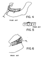
- the device 10 In order to immobilize one's jaw, while the patient is anesthitized, the device 10 is pushed between adjacent teeth 501 and 502 as shown in figure 12, and then, with a pair of pliers, the tip 14 is bent into the phantom position and thereafter pushed between the next adjacent teeth 502 and 503 so as to extend in the fashion of figure 13.
- the tip 14 is pulled taut, with a pair of pliers, in the direction of the arrow A so that the shaft 12 fits snug about the back of the tooth 502 and with the truncated conical surface 20 of the nut 17 resting snug against adjacent teeth 501 and 502, as shown in phantom in figure 13.
- the tip 14 is then moved with tweezers in the direction of arrow B and hence into the phantom position; and, then eventually wrapped about the segment of the helical shaft 15, disposed between nut 17 and the adjacent teeth 501 and 502, in the fashion shown in figure 14.
- the distal end or tip 14 of the shaft 12 (the phantom portion referred to as 14′ in figure 14) is cut away with a pair of wire cutters and discarded.
- the nut 15 is turned down snug on the helical thread to tighten the device 10 and to anchor it about the tooth 502 as shown in figure 3. Any excess helical thread 14 that protrudes into the truncated conical recess 25 of the nut 17 be removed with wire cutters. Any exposed ends of the shaft 11 are therefore removed and no scratching or other abrasion takes place in the mouth of the wearer when implanted. There is virtually no blood letting.
Landscapes
- Health & Medical Sciences (AREA)
- Life Sciences & Earth Sciences (AREA)
- Orthopedic Medicine & Surgery (AREA)
- Public Health (AREA)
- Veterinary Medicine (AREA)
- Animal Behavior & Ethology (AREA)
- General Health & Medical Sciences (AREA)
- Surgery (AREA)
- Heart & Thoracic Surgery (AREA)
- Otolaryngology (AREA)
- Engineering & Computer Science (AREA)
- Biomedical Technology (AREA)
- Dentistry (AREA)
- Epidemiology (AREA)
- Oral & Maxillofacial Surgery (AREA)
- Medical Informatics (AREA)
- Nuclear Medicine, Radiotherapy & Molecular Imaging (AREA)
- Molecular Biology (AREA)
- Neurology (AREA)
- Pulmonology (AREA)
- Nursing (AREA)
- Vascular Medicine (AREA)
- Dental Tools And Instruments Or Auxiliary Dental Instruments (AREA)
- Prostheses (AREA)
- Brushes (AREA)
- Surgical Instruments (AREA)
Priority Applications (1)
| Application Number | Priority Date | Filing Date | Title |
|---|---|---|---|
| AT89630153T ATE96636T1 (de) | 1988-09-27 | 1989-09-19 | Interdentale immobilisierungsvorrichtung. |
Applications Claiming Priority (4)
| Application Number | Priority Date | Filing Date | Title |
|---|---|---|---|
| CA000578613A CA1259866A (en) | 1988-09-27 | 1988-09-27 | Interdental immobilization device |
| CA578613 | 1988-09-27 | ||
| CA592368 | 1989-02-28 | ||
| CA 592368 CA1317517C (en) | 1989-02-28 | 1989-02-28 | Two part interdental immobilization device |
Publications (2)
| Publication Number | Publication Date |
|---|---|
| EP0366595A1 true EP0366595A1 (de) | 1990-05-02 |
| EP0366595B1 EP0366595B1 (de) | 1993-11-03 |
Family
ID=25672141
Family Applications (1)
| Application Number | Title | Priority Date | Filing Date |
|---|---|---|---|
| EP89630153A Expired - Lifetime EP0366595B1 (de) | 1988-09-27 | 1989-09-19 | Interdentale Immobilisierungsvorrichtung |
Country Status (8)
| Country | Link |
|---|---|
| US (1) | US4968248A (de) |
| EP (1) | EP0366595B1 (de) |
| JP (1) | JPH0329647A (de) |
| CN (1) | CN1019946C (de) |
| DE (1) | DE68910469T2 (de) |
| ES (1) | ES2045536T3 (de) |
| HU (1) | HUT51885A (de) |
| NZ (1) | NZ230488A (de) |
Cited By (1)
| Publication number | Priority date | Publication date | Assignee | Title |
|---|---|---|---|---|
| FR2970639A1 (fr) * | 2011-01-21 | 2012-07-27 | Thierry Perelli | Outil antitartre |
Families Citing this family (18)
| Publication number | Priority date | Publication date | Assignee | Title |
|---|---|---|---|---|
| US6257884B1 (en) * | 1999-10-14 | 2001-07-10 | Peter Chang | Maxillomandibular fixation device |
| US20030075186A1 (en) * | 2001-10-01 | 2003-04-24 | Florman Michael J. | Oral appliance and method for use in weight loss and control |
| KR100540638B1 (ko) * | 2003-10-13 | 2006-01-11 | 김중한 | 치아교정용 앵커식립장치 |
| US7780441B2 (en) * | 2005-04-21 | 2010-08-24 | Amundsen Ole C | Mounting device for orthodontic retainer elements and a method of maintaining said elements in place for mounting on corresponding teeth |
| US8147244B2 (en) * | 2005-05-05 | 2012-04-03 | Dellinger Eugene L | Orthodontic tooth retention system |
| US20070190476A1 (en) * | 2005-05-05 | 2007-08-16 | Dellinger Eugene L | Orthodontic tooth retention system |
| US20060252001A1 (en) * | 2005-05-05 | 2006-11-09 | Dellinger Eugene L | Method and apparatus for positioning an orthodontic appliance |
| US7854610B2 (en) * | 2005-05-05 | 2010-12-21 | Dellinger Eugene L | Orthodontic tooth retention system |
| JP4998958B2 (ja) * | 2006-08-25 | 2012-08-15 | 国立大学法人 長崎大学 | 睡眠時無呼吸症候群又はいびき症改善下顎前方位型口腔内装置用コネクター |
| IL188435A0 (en) * | 2007-12-26 | 2008-11-03 | Nobesity Ltd | Device and method for restraining food intake |
| US8083521B2 (en) * | 2008-04-30 | 2011-12-27 | Toads Llc | Anchor apparatus for orthodontic appliances |
| US20100285417A1 (en) * | 2009-05-05 | 2010-11-11 | Walther Russell B | System For Securing Intraoral Objects And Related Oral Structures |
| US8821497B2 (en) * | 2009-10-27 | 2014-09-02 | Howard D. Stupak | Method and apparatus for maxillo-mandibular fixation |
| WO2014189911A1 (en) | 2013-05-20 | 2014-11-27 | University Of Minnesota | Dental occlusion and tension band ties, systems and methods |
| US10531939B2 (en) * | 2016-03-15 | 2020-01-14 | Mitchell A. Stotland | Interdental anchoring apparatuses and methods |
| NO344576B1 (en) | 2018-01-12 | 2020-02-03 | Ole Christian Amundsen | Apparatus for aligning or positioning teeth |
| US20220202535A2 (en) * | 2018-05-14 | 2022-06-30 | Erskine Holdco Pty Ltd | An orthodontic anchorage assembly |
| DE102018132984B4 (de) * | 2018-12-19 | 2021-03-18 | Engeltech Gmbh | Interdentalschraube (Interdental screw) |
Citations (4)
| Publication number | Priority date | Publication date | Assignee | Title |
|---|---|---|---|---|
| US2481177A (en) * | 1944-08-22 | 1949-09-06 | Benjamin F Tofflemire | Intraoral fracture reduction appliance |
| US2502902A (en) * | 1946-01-25 | 1950-04-04 | Benjamin F Tofflemire | Intraoral fracture and orthodontic appliance |
| US4202328A (en) * | 1977-11-23 | 1980-05-13 | Sukkarie Ghassan A | Method and means for fixation and immobilization of the jaws |
| US4727867A (en) * | 1986-02-24 | 1988-03-01 | Knoderer William R | Mandibular lateral motion inhibitor |
Family Cites Families (1)
| Publication number | Priority date | Publication date | Assignee | Title |
|---|---|---|---|---|
| US4813869A (en) * | 1986-05-16 | 1989-03-21 | Gatewood John B | Jaw fixation assembly |
-
1989
- 1989-04-12 US US07/338,935 patent/US4968248A/en not_active Ceased
- 1989-08-30 NZ NZ230488A patent/NZ230488A/en unknown
- 1989-09-15 HU HU894846A patent/HUT51885A/hu unknown
- 1989-09-19 EP EP89630153A patent/EP0366595B1/de not_active Expired - Lifetime
- 1989-09-19 DE DE89630153T patent/DE68910469T2/de not_active Expired - Fee Related
- 1989-09-19 ES ES89630153T patent/ES2045536T3/es not_active Expired - Lifetime
- 1989-09-25 JP JP1250399A patent/JPH0329647A/ja active Pending
- 1989-09-25 CN CN89107485A patent/CN1019946C/zh not_active Expired - Fee Related
Patent Citations (4)
| Publication number | Priority date | Publication date | Assignee | Title |
|---|---|---|---|---|
| US2481177A (en) * | 1944-08-22 | 1949-09-06 | Benjamin F Tofflemire | Intraoral fracture reduction appliance |
| US2502902A (en) * | 1946-01-25 | 1950-04-04 | Benjamin F Tofflemire | Intraoral fracture and orthodontic appliance |
| US4202328A (en) * | 1977-11-23 | 1980-05-13 | Sukkarie Ghassan A | Method and means for fixation and immobilization of the jaws |
| US4727867A (en) * | 1986-02-24 | 1988-03-01 | Knoderer William R | Mandibular lateral motion inhibitor |
Cited By (2)
| Publication number | Priority date | Publication date | Assignee | Title |
|---|---|---|---|---|
| FR2970639A1 (fr) * | 2011-01-21 | 2012-07-27 | Thierry Perelli | Outil antitartre |
| EP2478862A3 (de) * | 2011-01-21 | 2012-09-19 | Thierry Perelli | Intrument zur Zahnsteinentfernung |
Also Published As
| Publication number | Publication date |
|---|---|
| HUT51885A (en) | 1990-06-28 |
| AU4158189A (en) | 1990-04-05 |
| CN1019946C (zh) | 1993-03-03 |
| CN1042066A (zh) | 1990-05-16 |
| JPH0329647A (ja) | 1991-02-07 |
| EP0366595B1 (de) | 1993-11-03 |
| DE68910469D1 (de) | 1993-12-09 |
| DE68910469T2 (de) | 1994-03-03 |
| US4968248A (en) | 1990-11-06 |
| NZ230488A (en) | 1992-07-28 |
| AU613793B2 (en) | 1991-08-08 |
| ES2045536T3 (es) | 1994-01-16 |
Similar Documents
| Publication | Publication Date | Title |
|---|---|---|
| US4968248A (en) | Interdental immobilization device | |
| US12408948B2 (en) | Intermaxillary fixation device and method of using same | |
| US12171475B2 (en) | Intermaxillary fixation device and method of using same | |
| US5853291A (en) | Subperiosteal bone anchor | |
| MXPA05011338A (es) | Implante dental de una sola pieza y uso del mismo en aplicaciones de prostodoncia y ortodoncia. | |
| JPH07500511A (ja) | 使い捨て式歯科用マトリックス保持クランプ | |
| USRE34249E (en) | Interdental immobilization device | |
| US4315739A (en) | Spring tensioning device and method | |
| US10980585B2 (en) | Intermaxillary fixation device and method of using same | |
| CA1317517C (en) | Two part interdental immobilization device | |
| PT91818B (pt) | dispositivo de imobilização interdental |
Legal Events
| Date | Code | Title | Description |
|---|---|---|---|
| PUAI | Public reference made under article 153(3) epc to a published international application that has entered the european phase |
Free format text: ORIGINAL CODE: 0009012 |
|
| AK | Designated contracting states |
Kind code of ref document: A1 Designated state(s): AT BE CH DE ES FR GB GR IT LI LU NL SE |
|
| 17P | Request for examination filed |
Effective date: 19900530 |
|
| 17Q | First examination report despatched |
Effective date: 19910710 |
|
| GRAA | (expected) grant |
Free format text: ORIGINAL CODE: 0009210 |
|
| AK | Designated contracting states |
Kind code of ref document: B1 Designated state(s): AT BE CH DE ES FR GB GR IT LI LU NL SE |
|
| REF | Corresponds to: |
Ref document number: 96636 Country of ref document: AT Date of ref document: 19931115 Kind code of ref document: T |
|
| ET | Fr: translation filed | ||
| REF | Corresponds to: |
Ref document number: 68910469 Country of ref document: DE Date of ref document: 19931209 |
|
| REG | Reference to a national code |
Ref country code: ES Ref legal event code: FG2A Ref document number: 2045536 Country of ref document: ES Kind code of ref document: T3 |
|
| ITF | It: translation for a ep patent filed | ||
| REG | Reference to a national code |
Ref country code: GR Ref legal event code: FG4A Free format text: 3010168 |
|
| PLBE | No opposition filed within time limit |
Free format text: ORIGINAL CODE: 0009261 |
|
| STAA | Information on the status of an ep patent application or granted ep patent |
Free format text: STATUS: NO OPPOSITION FILED WITHIN TIME LIMIT |
|
| 26N | No opposition filed | ||
| EAL | Se: european patent in force in sweden |
Ref document number: 89630153.8 |
|
| PGFP | Annual fee paid to national office [announced via postgrant information from national office to epo] |
Ref country code: LU Payment date: 19950801 Year of fee payment: 7 |
|
| PGFP | Annual fee paid to national office [announced via postgrant information from national office to epo] |
Ref country code: FR Payment date: 19950824 Year of fee payment: 7 |
|
| PGFP | Annual fee paid to national office [announced via postgrant information from national office to epo] |
Ref country code: DE Payment date: 19950826 Year of fee payment: 7 |
|
| PGFP | Annual fee paid to national office [announced via postgrant information from national office to epo] |
Ref country code: SE Payment date: 19950828 Year of fee payment: 7 Ref country code: CH Payment date: 19950828 Year of fee payment: 7 Ref country code: BE Payment date: 19950828 Year of fee payment: 7 |
|
| PGFP | Annual fee paid to national office [announced via postgrant information from national office to epo] |
Ref country code: NL Payment date: 19950829 Year of fee payment: 7 Ref country code: GB Payment date: 19950829 Year of fee payment: 7 |
|
| PGFP | Annual fee paid to national office [announced via postgrant information from national office to epo] |
Ref country code: AT Payment date: 19950904 Year of fee payment: 7 |
|
| PGFP | Annual fee paid to national office [announced via postgrant information from national office to epo] |
Ref country code: ES Payment date: 19950919 Year of fee payment: 7 |
|
| PGFP | Annual fee paid to national office [announced via postgrant information from national office to epo] |
Ref country code: GR Payment date: 19950929 Year of fee payment: 7 |
|
| PG25 | Lapsed in a contracting state [announced via postgrant information from national office to epo] |
Ref country code: LU Free format text: LAPSE BECAUSE OF NON-PAYMENT OF DUE FEES Effective date: 19960919 Ref country code: GB Effective date: 19960919 Ref country code: AT Effective date: 19960919 |
|
| PG25 | Lapsed in a contracting state [announced via postgrant information from national office to epo] |
Ref country code: SE Effective date: 19960920 Ref country code: ES Free format text: LAPSE BECAUSE OF THE APPLICANT RENOUNCES Effective date: 19960920 |
|
| PG25 | Lapsed in a contracting state [announced via postgrant information from national office to epo] |
Ref country code: LI Effective date: 19960930 Ref country code: FR Effective date: 19960930 Ref country code: CH Effective date: 19960930 Ref country code: BE Effective date: 19960930 |
|
| BERE | Be: lapsed |
Owner name: DIMAC MEDICAL LTD PARTNERSHIP Effective date: 19960930 |
|
| PG25 | Lapsed in a contracting state [announced via postgrant information from national office to epo] |
Ref country code: GR Free format text: THE PATENT HAS BEEN ANNULLED BY A DECISION OF A NATIONAL AUTHORITY Effective date: 19970331 |
|
| PG25 | Lapsed in a contracting state [announced via postgrant information from national office to epo] |
Ref country code: NL Effective date: 19970401 |
|
| REG | Reference to a national code |
Ref country code: GR Ref legal event code: MM2A Free format text: 3010168 |
|
| GBPC | Gb: european patent ceased through non-payment of renewal fee |
Effective date: 19960919 |
|
| REG | Reference to a national code |
Ref country code: CH Ref legal event code: PL |
|
| NLV4 | Nl: lapsed or anulled due to non-payment of the annual fee |
Effective date: 19970401 |
|
| PG25 | Lapsed in a contracting state [announced via postgrant information from national office to epo] |
Ref country code: DE Effective date: 19970603 |
|
| EUG | Se: european patent has lapsed |
Ref document number: 89630153.8 |
|
| REG | Reference to a national code |
Ref country code: FR Ref legal event code: ST |
|
| REG | Reference to a national code |
Ref country code: FR Ref legal event code: ST |
|
| REG | Reference to a national code |
Ref country code: ES Ref legal event code: FD2A Effective date: 19991102 |
|
| PG25 | Lapsed in a contracting state [announced via postgrant information from national office to epo] |
Ref country code: IT Free format text: LAPSE BECAUSE OF NON-PAYMENT OF DUE FEES;WARNING: LAPSES OF ITALIAN PATENTS WITH EFFECTIVE DATE BEFORE 2007 MAY HAVE OCCURRED AT ANY TIME BEFORE 2007. THE CORRECT EFFECTIVE DATE MAY BE DIFFERENT FROM THE ONE RECORDED. Effective date: 20050919 |