EP0366599B1 - Procédé pour transférer du matériel sur un support, appareil pour appliquer ce procédé et utilisation de l'appareil - Google Patents
Procédé pour transférer du matériel sur un support, appareil pour appliquer ce procédé et utilisation de l'appareil Download PDFInfo
- Publication number
- EP0366599B1 EP0366599B1 EP89810009A EP89810009A EP0366599B1 EP 0366599 B1 EP0366599 B1 EP 0366599B1 EP 89810009 A EP89810009 A EP 89810009A EP 89810009 A EP89810009 A EP 89810009A EP 0366599 B1 EP0366599 B1 EP 0366599B1
- Authority
- EP
- European Patent Office
- Prior art keywords
- zones
- application
- air
- permeable
- belt
- Prior art date
- Legal status (The legal status is an assumption and is not a legal conclusion. Google has not performed a legal analysis and makes no representation as to the accuracy of the status listed.)
- Expired - Lifetime
Links
- 239000000463 material Substances 0.000 title claims abstract description 20
- 238000000034 method Methods 0.000 title claims description 17
- 244000144992 flock Species 0.000 claims abstract description 17
- 238000003860 storage Methods 0.000 claims description 9
- 238000010521 absorption reaction Methods 0.000 claims description 5
- 239000002250 absorbent Substances 0.000 claims description 4
- 238000007664 blowing Methods 0.000 claims description 4
- 238000004140 cleaning Methods 0.000 claims description 4
- 239000000758 substrate Substances 0.000 claims 14
- 230000008021 deposition Effects 0.000 claims 4
- 239000003795 chemical substances by application Substances 0.000 claims 1
- 230000008030 elimination Effects 0.000 claims 1
- 238000003379 elimination reaction Methods 0.000 claims 1
- 238000011144 upstream manufacturing Methods 0.000 claims 1
- 230000000717 retained effect Effects 0.000 abstract 1
- 239000000835 fiber Substances 0.000 description 4
- 239000006096 absorbing agent Substances 0.000 description 3
- 230000000694 effects Effects 0.000 description 3
- 239000007788 liquid Substances 0.000 description 3
- 238000011161 development Methods 0.000 description 2
- 230000018109 developmental process Effects 0.000 description 2
- 238000004519 manufacturing process Methods 0.000 description 2
- 230000002745 absorbent Effects 0.000 description 1
- 239000004744 fabric Substances 0.000 description 1
- 238000005192 partition Methods 0.000 description 1
- 229920000058 polyacrylate Polymers 0.000 description 1
- 239000011148 porous material Substances 0.000 description 1
- 239000000843 powder Substances 0.000 description 1
- 239000000725 suspension Substances 0.000 description 1
- 239000012209 synthetic fiber Substances 0.000 description 1
- 229920002994 synthetic fiber Polymers 0.000 description 1
Images


Classifications
-
- D—TEXTILES; PAPER
- D06—TREATMENT OF TEXTILES OR THE LIKE; LAUNDERING; FLEXIBLE MATERIALS NOT OTHERWISE PROVIDED FOR
- D06Q—DECORATING TEXTILES
- D06Q1/00—Decorating textiles
- D06Q1/12—Decorating textiles by transferring a chemical agent or a metallic or non-metallic material in particulate or other form, from a solid temporary carrier to the textile
- D06Q1/14—Decorating textiles by transferring a chemical agent or a metallic or non-metallic material in particulate or other form, from a solid temporary carrier to the textile by transferring fibres, or adhesives for fibres, to the textile
Definitions
- the invention relates to a method for zone-by-zone application of fluffy material to a web-shaped, forward-moving base, a device for carrying out this method and the use of this device.
- Powdery liquid-absorbent material has the disadvantage, however, that after the diaper has been produced between the paper fibers, it can come to the outside of the diaper and thus come into skin contact with the skin surface of the toddler to be diapered, which is undesirable.
- the object of the present invention is, in particular, to provide a method which, in precisely metered form, enables flakes to be applied zone by zone to a forwardly moving base, such as a diaper web made of paper fibers.
- the invention further relates to a device for carrying out the method according to the invention.
- the invention also relates to a use of the device according to the invention as claimed in claim 15.
- a fiber-bonded liquid absorber based on polyacrylate in Form of flakes is applied zone by zone to a paper web.
- a liquid absorber is sold, for example, by the Hanfspinnerei Steen & Co. GmbH., D-2053 Schwarzenbek, under the name SAFF.
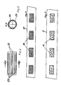
- the device shown for the zone-by-zone discharge of fluffy absorption material 1 onto a web-shaped, continuously advancing base 2 has a level-controlled storage container 3 for receiving the absorption material flakes 1 to be discharged and a controllably adjustable metering arrangement 5 which interacts with the outlet opening 4.
- This metering arrangement 5 consists of an endless needle belt 8, which is guided over two deflection rollers 6 and 7, the latter at its flake dispensing point B being in engagement with a rotating floack wiping roller 9, which hangs from the storage container in the needles projecting outward from the needle belt 8 3 stripped flakes 1 on the applicator assembly 10.
- the continuously rotating application arrangement 10 has, as can be seen in particular from FIG. 4, an application belt 12 which is designed to be air-permeable to zones on the support web 2 and is evident from FIG. 5 and which is guided over the deflection rollers 13, 14 and 15.
- the application tape 12 consists of an air-permeable wire or synthetic fiber fabric, which is coated with an air-impermeable plastic except for the zones 16 corresponding to the desired application pattern 11.
- the continuously rotating application belt 12 or its zone-permeable, air-permeable flock receiving points 16 stand during their movement from the delivery point B of the metering arrangement 5 until engagement with the underlay web 2 to be occupied, via a vacuum chamber 18 formed on the inside of the application belt 12 with a vacuum source 19 in connection.
- a blowing nozzle 21 directed towards the belt surface can additionally be provided, the blowing effect of which, however, is limited in such a way that the absorption flakes held on the belt surface by the regions 16 in these regions 16 are not also blown away.
- the air-permeable belt regions 16 are uncoupled from the negative pressure when they overflow over the deflection rollers 14 and 15, they are designed as slotted rollers, as can be seen from FIGS.
- the webs 22 between adjacent suction slots 23 should of course be as narrow as possible in order to achieve a suction effect that is as extensive as possible.
- suction slits, bores, pores or other air-permeable designs of the deflection roller outer sides are also conceivable.
- an overpressure chamber 24 is arranged in order to transfer the flakes located in these areas 16 to the top of the underlay 2 with the help of overpressure acting through the areas 16.
- a vacuum chamber 25 acting in this flake transfer area from below through the underlay 2 can also be provided.
- the deflecting roller 13 can, like the other deflecting rollers 14 and 15, also be designed as a slotted roller and connected to an overpressure source at this deflecting point or also integrated into the overpressure chamber 24.
- a cleaning roller 26 can also be provided for the complete cleaning of the application belt surface from any flakes and / or flake components that are still on the surface.
- the drive of the metering arrangement 5 and the discharge arrangement 10 is controlled in a controlled manner as a function of the speed of the support web 2 determined with the measuring device 27 with the aid of a computer 28.
- FIG. 6 shows a second exemplary embodiment of a device according to the invention, parts analogous to the first embodiment being provided with the same reference numerals, so that a repeated description of these parts is unnecessary.
- a needle roller 8 'and a discharge roller 12' are used instead of a needle belt 8 and an application belt 12, but everything else can remain the same.
- the flake container 3 is suspended in a vibratable manner via resilient suspensions 29 and connected to a vibrator 30.
- the discharge roller 12 ' is also provided on its cylindrical outer surface analogous to the discharge belt 12 with the desired application pattern 11 corresponding air-permeable areas 16, and the stationary partition 31 separates the inside of the discharge roller 12' in a vacuum region 18 and an overpressure region 24th
Landscapes
- Chemical & Material Sciences (AREA)
- Chemical Kinetics & Catalysis (AREA)
- General Chemical & Material Sciences (AREA)
- Engineering & Computer Science (AREA)
- Textile Engineering (AREA)
- Absorbent Articles And Supports Therefor (AREA)
- Decoration By Transfer Pictures (AREA)
- Mechanical Treatment Of Semiconductor (AREA)
- Polyesters Or Polycarbonates (AREA)
Claims (17)
- Procédé d'application par zones d'une matière floconneuse (1) sur un support en forme de bande (2) se déplaçant en avant, caractérisé en ce que l'on transfère la matière floconneuse (1) de manière dosée sur un agencement d'application tournant en continu et conformé en sorte d'être perméable à l'air par zones selon le schéma d'application souhaité, on retient la matière floconneuse (1) dans les zones perméables à l'air (16) via un vide agissant sur la partie inférieure de ces zones perméables à l'air (19), on élimine ensuite les flocons qui se trouvent en dehors de ces zones perméables à l'air (16) de la surface de l'agencement d'application (10), puis on amène à recouvrement les zones de l'agencement d'application pourvue des flocons (1) correspondant au schéma d'application souhaité avec le support en forme de bande (2) à revêtir par zones et finalement on dépose ces flocons sur le support en forme de bande à revêtir par zones par coupure du vide agissant sur eux.
- Procédé selon la revendication 1, caractérisé en ce que l'on décharge de manière dosée la matière floconneuse (1) sur une bande d'application (12) conformée de manière à être perméable à l'air par zones selon le schéma d'application souhaité.
- Procédé selon la revendication 1, caractérisé en ce que l'on décharge de manière dosée la matière floconneuse (1) sur un rouleau d'application (12′) conformé de manière à être perméable à l'air par zones selon le schéma d'application souhaité.
- Procédé selon l'une quelconque des revendications 1 à 3, caractérisé en ce que l'on décharge les flocons se trouvant sur l'agencement d'application (10) dans la zone de recouvrement avec le support à revêtir (2) après élimination du vide qui agit sur eux à l'aide d'une surpression agissant dans cette zone de recouvrement à travers les zones perméables à l'air de l'agencement d'application et/ou à l'aide d'un vide agissant dans cette zone de recouvrement à travers le support à revêtir.
- Procédé selon l'une quelconque des revendications 1 à 4, caractérisé en ce que l'on décharge de manière dosée la matière floconneuse (1) sur l'agencement d'application (10) via un dispositif de dosage (5) réglable sur commande à partir d'un réceptacle d'alimentation (3) dont le niveau de remplissage est contrôlé, la quantité dosée étant réglée en fonction de la vitesse du support à revêtir (2).
- Procédé selon la revendication 6, caractérisé en ce que l'on retire de manière dosée la matière floconneuse (1) via une bande à aiguilles sans fin (8) qui se déplace devant la sortie du réceptacle d'alimentation (3).
- Dispositif de mise en oeuvre du procédé selon la revendication 1, caractérisé en ce qu'il comporte un réceptacle d'alimentation (3) dont le niveau est contrôlé pour recevoir les flocons à appliquer, un agencement de dosage (5) réglable sur commande et coopérant avec l'entrée du réceptacle d'alimentation (3), un agencement d'application tournant en continu, conformé de manière à être perméable à l'air par zones selon le schéma d'application souhaité, coopérant d'une part avec le point de fourniture (B) de l'agencement de dosage (5) et susceptible d'être amené d'autre part à recouvrement avec le support à revêtir (2), ainsi qu'un dispositif d'évacuation (19) raccordable aux points récepteurs de flocons conformés de manière à être perméables à l'air, agencés par zones, au cours du déplacement de l'agencement d'application du point de fourniture (B) jusque contre la support à revêtir (2).
- Dispositif selon la revendication 7, caractérisé en ce que l'agencement d'application (10) tournant en continu est constitué d'une bande d'application (12) conformée en sorte d'être perméable à l'air par zones selon le schéma d'application (11) souhaité sur le support (2), la section de bande s'étendant parallèlement au support à revêtir (12) étant liée à une source de surpression d'air (32) sur son côté opposé au support à revêtir (2).
- Dispositif selon la revendication 8, cracartérisé en ce que la bande d'application (12) est guidée sur son chemin entre le point de fourniture (B) de l'agencement de dosage (5) et la zone de recouvrement avec le support en forme de bande (2) à revêtir via des rouleaux à fentes (14,15) de telle sorte qu'un vide présent autour de ceux-ci et appliqué sur les points de renvoi de bande ainsi formés puisse agir sans interruption sur les zones perméables à l'air (16) de la bande d'application (12), les rouleaux à fentes (14, 15) étant de préférence pourvus d'ouverture en forme de fentes (23) s'étendant mutuellement sur leur partie externe cylindrique entre leurs deux faces frontales ainsi qu'en liaison avec l'espace évacué (18).
- Dispositif selon la revendication 8, caractérisé en ce que la bande d'application (12) est constituée d'une matière perméable à l'air qui est revêtue d'une matière imperméable à l'air (17) jusque sur les zones (16) correspondant au schéma d'application souhaité.
- Dispositif selon l'une des revendication 7 à 10, caractérisé en ce que l'agencement de dosage (5) est constitué d'une bande à aiguilles ou à nopes (8) sans fin guidée sur au moins deux rouleau de renvoi (6, 7), cette bande venant en prise avec un rouleau extracteur de flocons (9) à son point de fourniture de flocons (B).
- Dispositif melon la revendication 8, caractérisé en ce que la bande d'application (12) est agencée en surplomb dans une partie de sa section de transport se trouvant devant le point de transfert de flocons (C), en liaison avec le dispositif d'évacuation (19), pour expulser les flocons qui ne se trouvent pas sur les zones perméables à l'air (16) de la bande d'application (16) et qui ne sont pas à transférer au support à revêtir (2), et, dans cette zone, une buse soufflante (21) est dirigée vers la partie externe de la bande d'application (12) de telle sorte que la force du jet ne puisse souffler que les flocons qui se trouvent dans cette zone sur les zones non perméables à l'air (16) de la bande d'application,
- Dispositif selon la revendication 8, caractérisé en ce qu'un rouleau de nettoyage (26) est affecté à la bande d'application (12) après la zone de transfert des flocons pour nettoyer sa surface externe.
- Dispositif selon l'une quelconque des revendications 7 à 13, caractérisé en ce que le réceptacle d'alimentation en flocons (3) est soumis à des vibrations via un vibrateur (30) auquel il est lié.
- Utilisation du dispositif selon la revendication 7 pour l'insertion par zones de matières absorbant les liquides présentes sous la forme de flocons dans un support en forme de bande constitué de fibres de papier.
- Utilisation selon la revendication 15 pour insertion de moyens d'absorption liés à des fibres.
- Utilisation selon la revendication 15 ou 16 pour la préparation d'articles d'hygiène absorbant les liquides.
Priority Applications (1)
| Application Number | Priority Date | Filing Date | Title |
|---|---|---|---|
| AT89810009T ATE81363T1 (de) | 1988-10-22 | 1989-01-09 | Verfahren zum auftragen von material auf eine unterlage, vorrichtung zur durchfuehrung des verfahrens und verwendung dieser vorrichtung. |
Applications Claiming Priority (2)
| Application Number | Priority Date | Filing Date | Title |
|---|---|---|---|
| CH3929/88 | 1988-10-22 | ||
| CH3929/88A CH678009A5 (fr) | 1988-10-22 | 1988-10-22 |
Publications (2)
| Publication Number | Publication Date |
|---|---|
| EP0366599A1 EP0366599A1 (fr) | 1990-05-02 |
| EP0366599B1 true EP0366599B1 (fr) | 1992-10-07 |
Family
ID=4266526
Family Applications (1)
| Application Number | Title | Priority Date | Filing Date |
|---|---|---|---|
| EP89810009A Expired - Lifetime EP0366599B1 (fr) | 1988-10-22 | 1989-01-09 | Procédé pour transférer du matériel sur un support, appareil pour appliquer ce procédé et utilisation de l'appareil |
Country Status (4)
| Country | Link |
|---|---|
| EP (1) | EP0366599B1 (fr) |
| AT (1) | ATE81363T1 (fr) |
| CH (1) | CH678009A5 (fr) |
| DE (1) | DE58902417D1 (fr) |
Families Citing this family (2)
| Publication number | Priority date | Publication date | Assignee | Title |
|---|---|---|---|---|
| IT1293123B1 (it) * | 1997-06-18 | 1999-02-11 | Michele Cripezzi | Metodo per la produzione di manufatti floccati e decorati, attrezzatura per detta produzione e manufatti cosi' realizzati. |
| CN100415388C (zh) * | 2006-06-13 | 2008-09-03 | 刘国方 | 转移植绒仿真人造皮革生产线 |
Family Cites Families (1)
| Publication number | Priority date | Publication date | Assignee | Title |
|---|---|---|---|---|
| GB712437A (en) * | 1950-12-20 | 1954-07-21 | Philippe Lebuy | Improved method and apparatus for printing fabrics with metallization |
-
1988
- 1988-10-22 CH CH3929/88A patent/CH678009A5/de not_active IP Right Cessation
-
1989
- 1989-01-09 AT AT89810009T patent/ATE81363T1/de not_active IP Right Cessation
- 1989-01-09 EP EP89810009A patent/EP0366599B1/fr not_active Expired - Lifetime
- 1989-01-09 DE DE8989810009T patent/DE58902417D1/de not_active Expired - Lifetime
Also Published As
| Publication number | Publication date |
|---|---|
| ATE81363T1 (de) | 1992-10-15 |
| CH678009A5 (fr) | 1991-07-31 |
| DE58902417D1 (de) | 1992-11-12 |
| EP0366599A1 (fr) | 1990-05-02 |
Similar Documents
| Publication | Publication Date | Title |
|---|---|---|
| DE69901390T2 (de) | Verfahren und gerät zur erzeugung von saugfähigen, aus durch luftströmung angeführten fasern bestehenden kernen | |
| DE69217541T2 (de) | Verfahren und Vorrichtung zum intermittierenden Auftragen von Pulver auf ein faseriges Substrat | |
| DE60023639T2 (de) | Verfahren zur Herstellung von Körpern mit einer Schicht von aufgebrachten Teilchen | |
| DE69217487T2 (de) | Verfahren und vorrichtung zum ablegen von partikeln auf ein sich bewegendes materialband | |
| DE3877771T2 (de) | Absorbierende unterlage. | |
| EP0085729B1 (fr) | Procédé et appareil pour revêtir un substrat avec un matériau très absorbant, en particulier un article hygiénique | |
| DE69021042T2 (de) | Verfahren und anlage zur herstellung von gleichmässig verteilten filamenten aus einem spinnfilament und herstellung des spinnvlieses. | |
| DE69629682T2 (de) | Verfahren und vorrichtung zur herstellung eines filters | |
| DE602005001413T2 (de) | Verfahren und Vorrichtung zur Beschichtung eines Gegenstands mit einem Partikel-Material | |
| DE69314464T2 (de) | Herstellung einer absorbierenden Schicht | |
| DE1760171B2 (de) | Vorrichtung zur Herstellung von Windeln für den einmaligen Gebrauch | |
| DE2439178A1 (de) | Verfahren zur herstellung einer vielzahl von fasern oder faeden aus einem thermoplastischen material | |
| DE3530084C2 (de) | Verfahren zum Behandeln von Zigaretten und Einrichtung zur Durchführung des Verfahrens | |
| EP0731151B1 (fr) | Procédé et dispositif pour le revêtement sous forme de trames avec des colles thermofusibles de configurations textiles en bande et flexibles | |
| DE4437165A1 (de) | Unidirektional flüssigkeitsdurchlässige Bahn | |
| DE3540388A1 (de) | Verfahren und vorrichtung zur herstellung von faserbahnverstaerkten kunststofflaminaten | |
| DE102005022269A1 (de) | Verfahren und Anlage zum Herstellen eines Hygieneartikels, insbesondere einer Windel | |
| DE69911729T2 (de) | Verfahren und Vorrichtung zum Anbringen von elastischen Elementen | |
| DE2726944C3 (de) | Verfahren zur Herstellung eines nichtgewebten Florstoffes und Vorrichtung zur Ausübung des Verfahrens | |
| EP0366599B1 (fr) | Procédé pour transférer du matériel sur un support, appareil pour appliquer ce procédé et utilisation de l'appareil | |
| DE3900619C2 (fr) | ||
| EP0864686B1 (fr) | Procédé et dispositif pour recouvrir des bandes de matériaux plats | |
| DE2040500C3 (de) | Verfahren und Vorrichtung zum Herstellen von verstärkten nichtgewebten Flächengebilden | |
| DE3636084A1 (de) | Verfahren zur erzeugung einer feuchtigkeitsdichten schicht | |
| DE2846220C3 (de) | Schweißmaschine für thermoplastische Folien mit kontinuierlich umlaufender Schweißwalze |
Legal Events
| Date | Code | Title | Description |
|---|---|---|---|
| PUAI | Public reference made under article 153(3) epc to a published international application that has entered the european phase |
Free format text: ORIGINAL CODE: 0009012 |
|
| AK | Designated contracting states |
Kind code of ref document: A1 Designated state(s): AT BE CH DE FR GB IT LI SE |
|
| 17P | Request for examination filed |
Effective date: 19900529 |
|
| 17Q | First examination report despatched |
Effective date: 19910820 |
|
| GRAA | (expected) grant |
Free format text: ORIGINAL CODE: 0009210 |
|
| AK | Designated contracting states |
Kind code of ref document: B1 Designated state(s): AT BE CH DE FR GB IT LI SE |
|
| REF | Corresponds to: |
Ref document number: 81363 Country of ref document: AT Date of ref document: 19921015 Kind code of ref document: T |
|
| GBT | Gb: translation of ep patent filed (gb section 77(6)(a)/1977) | ||
| REF | Corresponds to: |
Ref document number: 58902417 Country of ref document: DE Date of ref document: 19921112 |
|
| ITF | It: translation for a ep patent filed | ||
| ET | Fr: translation filed | ||
| PLBE | No opposition filed within time limit |
Free format text: ORIGINAL CODE: 0009261 |
|
| STAA | Information on the status of an ep patent application or granted ep patent |
Free format text: STATUS: NO OPPOSITION FILED WITHIN TIME LIMIT |
|
| 26N | No opposition filed | ||
| EAL | Se: european patent in force in sweden |
Ref document number: 89810009.4 |
|
| PGFP | Annual fee paid to national office [announced via postgrant information from national office to epo] |
Ref country code: SE Payment date: 19951212 Year of fee payment: 8 |
|
| PGFP | Annual fee paid to national office [announced via postgrant information from national office to epo] |
Ref country code: FR Payment date: 19951228 Year of fee payment: 8 |
|
| PGFP | Annual fee paid to national office [announced via postgrant information from national office to epo] |
Ref country code: AT Payment date: 19960116 Year of fee payment: 8 |
|
| PGFP | Annual fee paid to national office [announced via postgrant information from national office to epo] |
Ref country code: DE Payment date: 19960224 Year of fee payment: 8 |
|
| PGFP | Annual fee paid to national office [announced via postgrant information from national office to epo] |
Ref country code: CH Payment date: 19960410 Year of fee payment: 8 |
|
| PGFP | Annual fee paid to national office [announced via postgrant information from national office to epo] |
Ref country code: GB Payment date: 19961231 Year of fee payment: 9 |
|
| PG25 | Lapsed in a contracting state [announced via postgrant information from national office to epo] |
Ref country code: AT Effective date: 19970109 |
|
| PG25 | Lapsed in a contracting state [announced via postgrant information from national office to epo] |
Ref country code: SE Effective date: 19970110 |
|
| PGFP | Annual fee paid to national office [announced via postgrant information from national office to epo] |
Ref country code: BE Payment date: 19970110 Year of fee payment: 9 |
|
| PG25 | Lapsed in a contracting state [announced via postgrant information from national office to epo] |
Ref country code: LI Effective date: 19970131 Ref country code: CH Effective date: 19970131 |
|
| REG | Reference to a national code |
Ref country code: CH Ref legal event code: PL |
|
| PG25 | Lapsed in a contracting state [announced via postgrant information from national office to epo] |
Ref country code: FR Effective date: 19970930 |
|
| PG25 | Lapsed in a contracting state [announced via postgrant information from national office to epo] |
Ref country code: DE Effective date: 19971001 |
|
| EUG | Se: european patent has lapsed |
Ref document number: 89810009.4 |
|
| REG | Reference to a national code |
Ref country code: FR Ref legal event code: ST |
|
| PG25 | Lapsed in a contracting state [announced via postgrant information from national office to epo] |
Ref country code: GB Free format text: LAPSE BECAUSE OF NON-PAYMENT OF DUE FEES Effective date: 19980109 |
|
| PG25 | Lapsed in a contracting state [announced via postgrant information from national office to epo] |
Ref country code: BE Free format text: LAPSE BECAUSE OF NON-PAYMENT OF DUE FEES Effective date: 19980131 |
|
| BERE | Be: lapsed |
Owner name: SANTEX A.G. Effective date: 19980131 |
|
| GBPC | Gb: european patent ceased through non-payment of renewal fee |
Effective date: 19980109 |
|
| PG25 | Lapsed in a contracting state [announced via postgrant information from national office to epo] |
Ref country code: IT Free format text: LAPSE BECAUSE OF NON-PAYMENT OF DUE FEES;WARNING: LAPSES OF ITALIAN PATENTS WITH EFFECTIVE DATE BEFORE 2007 MAY HAVE OCCURRED AT ANY TIME BEFORE 2007. THE CORRECT EFFECTIVE DATE MAY BE DIFFERENT FROM THE ONE RECORDED. Effective date: 20050109 |