EP0366682B1 - Systeme de commande de temperature pour processeur photographique - Google Patents
Systeme de commande de temperature pour processeur photographique Download PDFInfo
- Publication number
- EP0366682B1 EP0366682B1 EP88905512A EP88905512A EP0366682B1 EP 0366682 B1 EP0366682 B1 EP 0366682B1 EP 88905512 A EP88905512 A EP 88905512A EP 88905512 A EP88905512 A EP 88905512A EP 0366682 B1 EP0366682 B1 EP 0366682B1
- Authority
- EP
- European Patent Office
- Prior art keywords
- fluid
- temperature
- tank
- fluids
- tanks
- Prior art date
- Legal status (The legal status is an assumption and is not a legal conclusion. Google has not performed a legal analysis and makes no representation as to the accuracy of the status listed.)
- Expired - Lifetime
Links
- 239000012530 fluid Substances 0.000 claims abstract description 85
- 238000010438 heat treatment Methods 0.000 claims abstract description 47
- 238000012545 processing Methods 0.000 claims abstract description 26
- 230000000737 periodic effect Effects 0.000 claims description 4
- 238000000034 method Methods 0.000 abstract 1
- 239000004020 conductor Substances 0.000 description 14
- 230000003134 recirculating effect Effects 0.000 description 13
- 238000001035 drying Methods 0.000 description 10
- 239000003381 stabilizer Substances 0.000 description 8
- 238000010276 construction Methods 0.000 description 6
- 239000007844 bleaching agent Substances 0.000 description 5
- 230000000087 stabilizing effect Effects 0.000 description 4
- 230000001143 conditioned effect Effects 0.000 description 2
- 239000004727 Noryl Substances 0.000 description 1
- 229920001207 Noryl Polymers 0.000 description 1
- 238000013459 approach Methods 0.000 description 1
- 238000004061 bleaching Methods 0.000 description 1
- 238000002474 experimental method Methods 0.000 description 1
- 239000007788 liquid Substances 0.000 description 1
- 238000012423 maintenance Methods 0.000 description 1
- 239000002184 metal Substances 0.000 description 1
- 238000012544 monitoring process Methods 0.000 description 1
- 239000004033 plastic Substances 0.000 description 1
- 238000004513 sizing Methods 0.000 description 1
Images


Classifications
-
- G—PHYSICS
- G03—PHOTOGRAPHY; CINEMATOGRAPHY; ANALOGOUS TECHNIQUES USING WAVES OTHER THAN OPTICAL WAVES; ELECTROGRAPHY; HOLOGRAPHY
- G03D—APPARATUS FOR PROCESSING EXPOSED PHOTOGRAPHIC MATERIALS; ACCESSORIES THEREFOR
- G03D13/00—Processing apparatus or accessories therefor, not covered by groups G11B3/00 - G11B11/00
- G03D13/006—Temperature control of the developer
-
- G—PHYSICS
- G05—CONTROLLING; REGULATING
- G05D—SYSTEMS FOR CONTROLLING OR REGULATING NON-ELECTRIC VARIABLES
- G05D23/00—Control of temperature
- G05D23/19—Control of temperature characterised by the use of electric means
- G05D23/1906—Control of temperature characterised by the use of electric means using an analogue comparing device
- G05D23/1913—Control of temperature characterised by the use of electric means using an analogue comparing device delivering a series of pulses
-
- G—PHYSICS
- G05—CONTROLLING; REGULATING
- G05D—SYSTEMS FOR CONTROLLING OR REGULATING NON-ELECTRIC VARIABLES
- G05D23/00—Control of temperature
- G05D23/19—Control of temperature characterised by the use of electric means
- G05D23/20—Control of temperature characterised by the use of electric means with sensing elements having variation of electric or magnetic properties with change of temperature
- G05D23/24—Control of temperature characterised by the use of electric means with sensing elements having variation of electric or magnetic properties with change of temperature the sensing element having a resistance varying with temperature, e.g. a thermistor
Definitions
- the present invention relates to a photographic processor comprising a developing tank and at least two additional processing tanks, each of the tanks being provided with heating means, first sensing means disposed in thermal relationship with said developing fluid for sensing the temperature of said developing fluid in the developing tank; and first control means responsive to said first sensing means for controlling the heating means associated with said developing tank so as to maintain said developing fluid at a predetermined operating temperature.
- Photographic processors of the type used to develop conventional photographic film or paper, utilize a plurality of processing fluids which must be maintained at precise temperatures.
- a typical photographic paper processor includes, for example, six discrete tanks of processing fluids including: a developing fluid, a bleaching fluid, and four separate tanks of stabilizing fluids. The temperature of each of these fluids must be maintained, within a certain tolerance, at a precise setting. Further, the fluids can't be intermixed, so it is necessary to separately maintain the temperature of each fluid in each tank.
- Each temperature control system includes its own temperature sensor situated in the fluid, its own heating element also situated in the fluid, and its own control electronics connected to both the temperature sensor and the heater.
- Each temperature control system operates by monitoring the temperature of the sensor with the control electronics, and using the control electronics to actuate the heating element as required. While providing extremely precise temperature control, the use of such individual temperature control systems is expensive. Further, they require a substantial quantity of complex electronic parts, adding to the complexity, bulk, and difficulty in maintaining the photographic processors employing them.
- the British Patent 630 252 discloses a photographic processor which comprises a plurality of processing tanks for containing separated processing fluids, wherein the required temperature of each one of the processing fluids is reached and maintained by passing an alternate current through the conductive walls of the tanks, which heats the walls and the solutions.
- a temperature sensor consisting of a thermostat element is installed in only one of the tanks and actuates the source of the current such that the temperature of the processing fluids contained in the tanks remains at a predetermined value.
- the present invention constitutes a photographic processor in accordance with the first part of claim 1, which is further characterized by second sensing means disposed in thermal relationship with said fluids of one of said additional processing tanks for sensing the temperature of said fluids in said processing tanks; and second control means responsive to said second sensing means for controlling the heating means associated with said additional processing tank so as to maintain the fluids of said additional processing tanks at a predetermined operating temperature.
- a new and improved photographic processor comprises a first tank containing a heated first processing fluid and second and third tanks containing second and third processing fluids, respectively.
- Temperature controlling means are provided, responsive to the temperature of a selected one of the second or third processing fluids, for controlling the temperatures of both said second and third processing fluids.
- This temperature controlling means includes a single temperature sensor disposed in thermal relationship with one of the second or third processing fluids, and first and second heating elements disposed in thermal relationship with, and having heat outputs proportional to, the volume of the second and third processing fluids, respectively.
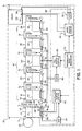
- a photographic paper processor 10 includes a tank 12 of developing fluid 14.
- a "tail" portion 16 of processor 10 comprises five tanks: a tank 18 containing bleach/fix 20, and four tanks 22, 24, 26, 28 containing first, second, third and fourth stabilizing fluids, 30, 32, 34, 36, respectively.
- Tanks 12, 18, and 22-28 are substantially identical except for size and fluid capacity, which will be discussed in detail below. For purposes of explanation, only tank 12 will be described and labeled in detail.
- Tank 12 comprises, along its lower edge (as viewed in FIGS. 1 and 2, a first recirculating conduit 38 including a drain outlet 40 and a recirculating outlet 42. Proximate its upper edge, tank 12 includes an overflow conduit 44 having an overflow outlet 46 therein. Underlying overflow conduit 44, but still proximate the upper edge of tank 12, is a second recirculating conduit 48 including an inlet 50. Connected between recirculating outlet 42 and recirculating inlet 50, with fluid-tight seals (not shown), is a pump 52.
- Tanks 12, 18, 22-28 are preferably constructed of a thermally insulating, chemically resistant plastic such as Noryl, available from General Electric Co.
- Pump 52 comprises, for example, a model 15570 pump available from Gorman-Rupp Ind., a division of Gorman-Rupp Co.
- Drying compartment 54 comprises a hot air dryer of a type well known to those of ordinary skill in the art.
- a continuous web of photographic paper 51 is shown being transported by rollers 53 from a paper holder 55 sequentially through the fluids in tanks 12, 18, 22-28, drying compartment 54, and out of printer 10.
- Heating elements 56-68 Disposed in first recirculating conduit 38 of each tank 12, 18, 22-28, and inside drying compartment 54, is an electrically resistive heating element, the seven heating elements being indicated at 56, 58, 60, 62, 64, 66, 68, respectively. Heating elements 56-68 are identical excepting in size which is discussed in detail below. As used herein with reference to heating elements, the term "size" is defined as the heating capacity in watts of a heating element. Each heating element 56-68 is disposed in thermal relationship with the fluid contained in its corresponding tank, or, in the case of drying compartment 54, with the air in the dryer.
- a first thermistor 70 is disposed in recirculating conduit 38 of tank 12, between heating element 56 and recirculating outlet 42.
- a second thermistor 72 is disposed in the same region of tank 24.
- a third thermistor 74 is disposed in drying compartment 54. It will be appreciated that thermistors 70, 72 are disposed in thermal relationship with developer fluid 14 and second stabilizer fluid 32, respectively, while thermistor 74 is disposed in thermal relationship with the air in drying compartment 54.
- Temperature control circuit 80 includes a developer heater control circuit 82 connected to thermistor 70, and to heating element 56 via an intermediately disposed solid-state relay (SSR) 84.
- a heater control circuit 86 for tail portion 16 of paper processor 10 is connected to thermistor 72, and to heating elements 58-66 via a single, intermediately disposed SSR 88.
- a dryer heater control circuit 90 is connected to thermistor 74, and to heating element 68 via a third, intermediately disposed SSR 92.
- control circuits 82, 86, and 90 are identical in construction.
- a periodic wave generator in this preferred embodiment of the invention comprising triangular wave generator 94, is connected to developer, tail, and dryer heater control circuits 82, 86, and 90, respectively.
- Thermistors 70, 72, and 74 each comprise, for example, model UUA41J1 elements disposed in model H110 cases as available from the Fenwall Electronics Co.
- Heaters 56-68 each comprise, for example, Firerod type heaters available from Watlow Co.
- developer control circuit 82 includes an electronic bridge circuit 95 having thermistor 70 connected in an arm thereof.
- the output of bridge circuit 95 is connected to the input of a voltage amplifier 96 via a pair of conductors 98, 100.
- the output of amplifier 96 is connected to one input of an adder/comparator (ADD/COMP) 102 via a conductor 104, the output of the ADD/COMP in turn being connected to SSR 84 via a conductor 106.
- Triangle wave generator 94 includes two outputs connected to second and third inputs of ADD/COMP 102 via conductors 108, 110, respectively.
- triangle wave generator 94 is used to generate two signals, a signal V TW of periodic waveform (preferably triangular) on conductor 108, and a D.C. level offset voltage V OS on conductor 110.
- Control circuits 86 and 90 are identical in construction to developer control circuit 82.
- Triangle wave generator 94 comprises any suitable electronic circuit, many of which are known to those skilled in the art. It will be understood that offset voltage V OS needn't be derived from triangular wave generator 94, but may comprise a separate, suitable circuit for generating a D.C. level.
- Bridge circuit 94 comprises, for example, precision metal film resistors connected in a bridge configuration well known to those skilled in the art.
- Amplifier 96 comprises, for example, a model LF412AN integrated circuit available from National Semiconductor Co.
- ADD/COMP 102 comprises, for example, an LF412AN integrated circuit configured as an adder, and an LM319N integrated circuit configured as a comparator, both integrated circuits being commercially available from the National Semiconductor Co.
- ADD/COMP 102 functions to sum the inputs on conductors 104 and 110, and to compare the sum to the input on 108. If the sum of the inputs on 104, 110 is less than the input on 108, the output on conductor 106 goes low. If the sum is greater than the single input, the output goes high.
- tanks 12, 18, 22-28 are filled with fluids of the type described above, and pumps 52 are actuated to recirculate the fluid within each tank.
- the fluid in each tank 12, 18, 22-28 recirculates from the interior of the tank, down and out through recirculating conduit 38 and outlet 40.
- the fluid is then pumped through pump 52, into recirculating inlet 46, through second recirculating conduit 44 and back into the tank.
- control circuits 86 and 90 being identical in construction and operation to control circuit 82, for purposes of explanation, only the operation of control circuit 82 will be described in detail herein.
- the size, or heating capacity, of heaters 56-66 are selected.
- the remaining heating elements 62, 64, 66 are similarly sized in proportion to the quantity of fluid 32-36 contained in their respective tanks 24-28.
- the size of heaters 56-66 are preferably selected so as to be able to heat their corresponding fluids 14, 20, 30-36 from an ambient temperature of about 21 degrees centigrade to desired operating temperatures in a predetermined period of time. In the preferred embodiment of the invention, this preselected period of time is less than one hour.
- Heating element 68 in drying compartment 54 is selected to provide sufficient heat to dry wet paper.
- bridge circuit 95 outputs two separate voltages.
- a first voltage, indicated as V T on conductor 98, is representative of the temperature sensed in developing fluid 14 by thermistor 70.
- a second voltage, indicated as V R on conductor 100, is representative of a desired, predetermined operating temperature for developing fluid 14.
- voltage V R is selected by adjustment of a variable resistance (not shown) in bridge circuit 95.
- Amplifier 96 senses the difference between voltages V T and V R , and generates a proportional, amplified, error voltage V E indicated on conductor 104.
- Triangle wave generator 94 generates two voltages supplied to ADD/COMP 102, triangular wave V TW , of uniform period, indicated on conductor 108, and offset voltage V OS indicated on conductor 110.
- Triangular wave V TW varies between upper and lower voltages V H and V L , respectively.
- ADD/COMP 102 sums offset voltage V OS with error voltage V E , this sum being represented by the appropriately labeled plot. ADD/COMP 102 then compares the summation V OS + V E with V TW , and responsively generates a control voltage V C on conductor 106. When the summation V OS + V E is less than V TW , than V C is a logical 0 (or low), and SSR 84 is conditioned to actuate heating element 56. When the summation V OS + V E is equal to or greater than V TW , then V C is a logical 1 (or high), and SSR 84 is conditioned to shut off heating element 56.
- V OS + V E when V OS + V E is less than the lowest level V L of triangular wave V TW , which is true for time T is less than T1, control voltage V C is low and heating element 56 is powered on.
- V OS + V E is greater than or equal to V TW , as occurs for time T is greater than T5
- control voltage V C goes high and heater element 56 is inactivated.
- V OS + V E is greater than V L and less than V H
- heating element 56 is controlled according to the periodic nature of triangular wave V TW . More specifically, V C is low when V OS + V E is less than V TW , a condition which occurs during the time T is greater than T1 and less than T2, and T is greater than T3 and less than T4.
- V C goes to the high condition when V OS + V E is greater than V TW , a condition which occurs when time T is greater than T2 and less than T3, and when T is greater than T4 and less than T5.
- heating element 56 when developing fluid 14 is relatively cold (i.e. when V OS + V E is less than V L ), heating element 56 is on all of the time.
- the temperature of developing fluid 14 approaches the predetermined operating temperature (i.e. when V OS + V E is greater than V L but less than V H )
- heater 56 is on only part of the time, as determined by the period of V TW , slowing down the rate of heating.
- the temperature of developing fluid 14 equals or exceeds the predetermined temperature (i.e. V OS + V E is equal to or greater than V H )
- heating element 56 is off.
- the control provided by temperature control circuit 80 is thus very accurate, heating the cold temperature quickly to operating temperature while preventing overshoot. Temperature control circuit 80 further operates to very closely maintain the desired operating temperature.
- Tail heater control circuit 86 functions identically to developer heater control circuit 82, with the exception that its input is provided by thermistor 72, and its control signal V C is used to actuate SSR 88.
- V C the control signal used to actuate SSR 88.
- tail heater control circuit 86 is used to control the temperature of all five tail fluids 20, 30-36 in their corresponding tanks 18, 22-28. This is accomplished by using V C' , in the manner described above, to condition SSR 88 to actuate all five parallel-connected heating elements 58-66.
- Table 1 TANK FLUID VOLUME HEATER WATTAGE Developer 12 13,5 Liter 300 Watts Bleach/fix 18 13,5 Liter 300 Watts Stabilizer 22 6,75 Liter 150 Watts Stabilizer 24 6,75 Liter 150 Watts Stabilizer 26 6,75 Liter 150 Watts Stabilizer 28 6,75 Liter 150 Watts
- the temperature of developing fluid 14 in tank 12 was maintained at 35 degrees centigrade plus-or-minus 0.15 degree centigrade.
- the temperatures of the tail fluids, bleach/fix 30 and stabilizers 32-36 were maintained at 35 degrees centigrade plus-or-minus 3.0 degrees centigrade, well within operational limits. Further, the various fluids were brought up to operating temperatures in 1/2 hour after an overnight shut-down, and within 1 hour after refilling with fresh fluids having ambient temperatures of about 21 degrees centigrade.
- Dryer heater control circuit 90 operates identically to developer heater control circuit 82 as described above, control signal V C' , actuating SSR 92 and heating element 68 responsive to the temperature sensed by thermistor 74.
- the bridge circuit 94 in dryer heater control circuit 90 can be implemented with a variable resistor in one arm thereof, permitting the dryer temperature to be varied.
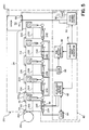
- Film processor 210 includes a tail portion 211, and is identical in structure to paper processor 10 (FIGS. 1-3), with the exception of the quantities and types of fluids used therein.
- Film processor 210 includes five tanks 212-220, tank 212 containing a developing fluid 222, tank 214 containing a bleach 224, tanks 216 and 218 each containing fixing fluids 226 and 228 respectively, and tank 220 containing a stabilizing fluid 230.
- Film processor 210 further includes a drying compartment 54 identical in construction and operation to the like-numbered drying compartment described above. For purposes of explanation, a continuous web of film 250 is shown being carried by rollers 53 out of a paper holder 252, through the processing fluids in tanks 212-220, through dryer 54, and out of processor 210.
- Each tank 212-220 is identical in construction to tanks 12, 18, 20-28 described above, and each includes a heating element 234-242, respectively, in the first recirculating conduit 38 thereof.
- a first thermistor 246 is disposed in the recirculating conduit 38 of developing tank 212, and a second thermistor 248 is disposed in the like region of second fixer tank 228.
- Temperature control circuit 80 is identical in construction and operation to the like-numbered temperature control circuit described above.
- developer heater control circuit 82 operates to control the temperature of developing fluid 222 via heating element 234 and SSR 84 in a manner identical to that described above.
- Tail heater control circuit 86 functions to control the temperature of fluids 224-230 in tanks 214-220, respectively, via SSR 88 and parallel-connected heating elements 236-242, in a manner identical to that described above.
- Dryer control circuit 90 operates to control the temperature of the air in dryer compartment 54, also in a manner identical to that described above.
- photographic film processor 210 was tested using the parameters set out in Table 2 below: Table 2 TANK FLUID VOLUME HEATER WATTAGE Developer 12 13,5 Liter 300 Watts Bleach 214 13,5 Liter 300 Watts Fixer 216 13,5 Liter 300 Watts Fixer 218 13,5 Liter 300 Watts Stabilizer 220 13,5 Liter 300 Watts It was found that the temperature of developing fluid 222 could be maintained at 37.8 degrees centigrade plus-or-minus 0.15 degree centigrade. The temperatures of the tail fluids, bleach 224, first fixer 226, second fixer 228 and stabilizer 230, could be maintained at 37.8 degrees centigrade, plus-or-minus 3.0 degrees centigrade. These temperatures are well within operational limits. Further, the fluids in the paper processor could be brought up to operating temperature within 1/2 hour after an overnight shutdown, and within 1 hour after refilling with fresh fluids at an ambient temperature of approximately 21 degrees centigrade.
- photographic film and paper processors including relatively simple temperature control apparatus which controls critical fluid temperatures to a higher tolerance than non-critical fluid temperatures.
- the control of the less critical temperatures is done using fewer and thus simpler control electronics than is found in other contemporary photographic processors.
Landscapes
- Physics & Mathematics (AREA)
- General Physics & Mathematics (AREA)
- Engineering & Computer Science (AREA)
- Automation & Control Theory (AREA)
- Photographic Processing Devices Using Wet Methods (AREA)
Abstract
Claims (3)
- Processeur photographique comprenant une cuve de développement (12) et au moins deux cuves de traitement supplémentaires (18 et 22 à 28), chacune des cuves étant muni d'un moyen chauffant (56, 58 et 60 à 66),
un premier moyen de détection (70) disposé en relation thermique avec le fluide de développement (14) pour détecter la température du fluide de développement dans la cuve de développement (12) et
un premier moyen de commande (82) répondant audit premier moyen de détection (70) pour commander le moyen chauffant (56) associé à ladite cuve de développement de façon à maintenir ledit fluide de développement (14) à une température de fonctionnement prédéterminée ; caractérisé par
un second moyen de détection (72) disposé en relation thermique avec le fluide (32) d'une desdites cuves de traitement supplémentaires (18 et 22 à 28) pour détecter la température du fluide dans ladite cuve parmi lesdites cuves de traitement supplémentaires et
un second moyen de commande (86) répondant audit second moyen de détection (72) pour commander les moyens chauffants (58 et 60 à 66) associés auxdites cuves de traitement supplémentaires de façon à maintenir les fluides (20 et 30 à 36) desdites cuves de traitement supplémentaires à une température de fonctionnement prédéterminée. - Processeur photographique selon la revendication 1, caractérisé par un moyen (94) pour produire un signal de commande électronique ayant une onde périodique (VTW) ; et lesdits moyens de commande (82, 86) étant chacun sensible audit signal de commande électronique pour commander leur moyen chauffant respectif (56 et 58 à 66).
- Processeur photographique selon la revendication 1 et 2, caractérisé en ce que chacun desdits moyens de commande (82, 86) comprend :
un moyen de production de signal d'erreur (95, 96) répondant à un desdits moyens de détection de température (70, 72) pour produire un signal électronique représentatif de la différence entre la température du fluide détecté (VT) et la température prédéterminée (VR) pour ce fluide ; et
un moyen de comparateur (102) répondant audit signal d'erreur (VF) et audit signal de commande (VC) pour produire un signal d'actionnement pour alimenter au moins un desdits moyens chauffant (56 et 58 à 66).
Applications Claiming Priority (3)
| Application Number | Priority Date | Filing Date | Title |
|---|---|---|---|
| US07/060,893 US4755843A (en) | 1987-06-12 | 1987-06-12 | Temperature control system for a photographic processor |
| US60893 | 1987-06-12 | ||
| PCT/US1988/001788 WO1988009959A1 (fr) | 1987-06-12 | 1988-05-31 | Systeme de commande de temperature pour processeur photographique |
Publications (2)
| Publication Number | Publication Date |
|---|---|
| EP0366682A1 EP0366682A1 (fr) | 1990-05-09 |
| EP0366682B1 true EP0366682B1 (fr) | 1994-08-03 |
Family
ID=22032395
Family Applications (1)
| Application Number | Title | Priority Date | Filing Date |
|---|---|---|---|
| EP88905512A Expired - Lifetime EP0366682B1 (fr) | 1987-06-12 | 1988-05-31 | Systeme de commande de temperature pour processeur photographique |
Country Status (5)
| Country | Link |
|---|---|
| US (1) | US4755843A (fr) |
| EP (1) | EP0366682B1 (fr) |
| JP (1) | JP2726073B2 (fr) |
| DE (1) | DE3850971T2 (fr) |
| WO (1) | WO1988009959A1 (fr) |
Families Citing this family (7)
| Publication number | Priority date | Publication date | Assignee | Title |
|---|---|---|---|---|
| AU608579B2 (en) * | 1987-03-24 | 1991-04-11 | Konica Corporation | Apparatus and method for treating photographic process waste liquor through concentration by evaporation |
| EP0327674A3 (fr) * | 1988-02-12 | 1990-09-05 | ING. HERMANN KÜMMERL, LABORGERÄTEBAU, Inh. Ing. Klaus Kümmerl | Machine de développement photographique |
| JP2640520B2 (ja) * | 1988-11-16 | 1997-08-13 | コニカ株式会社 | 写真感光材料の処理方法及び処理機 |
| US5235371A (en) * | 1990-03-16 | 1993-08-10 | Eastman Kodak Company | Modification of film processor chemistry proportional heating during replenishment |
| JP3165290B2 (ja) * | 1993-07-26 | 2001-05-14 | 富士写真フイルム株式会社 | 感光材料処理装置の処理液温度制御方式 |
| JPH0887100A (ja) * | 1994-09-20 | 1996-04-02 | Noritsu Koki Co Ltd | 写真処理機の温度調節方法およびその装置 |
| US20060282097A1 (en) * | 2005-06-13 | 2006-12-14 | Ortiz Mark S | Surgical suturing apparatus with a non-visible spectrum sensing member |
Citations (1)
| Publication number | Priority date | Publication date | Assignee | Title |
|---|---|---|---|---|
| GB630252A (en) * | 1946-08-13 | 1949-10-10 | Edward Albert James Tunnicliff | Improvements in photographic processing equipment |
Family Cites Families (12)
| Publication number | Priority date | Publication date | Assignee | Title |
|---|---|---|---|---|
| US1967889A (en) * | 1930-08-05 | 1934-07-24 | Keller Dorian Colorfilm Corp | Machine for developing goffered moving picture films |
| GB630251A (en) * | 1946-08-12 | 1949-10-10 | King Ltd Geo W | Improvements in or relating to conveyor systems |
| US3526272A (en) * | 1968-07-29 | 1970-09-01 | Tronac Inc | Servo temperature control |
| US3613547A (en) * | 1969-01-23 | 1971-10-19 | Picker Corp | Film processor |
| GB1276382A (en) * | 1969-05-02 | 1972-06-01 | Cordell Engineering Inc | Photographic processing apparatus |
| US3586829A (en) * | 1969-12-29 | 1971-06-22 | Us Navy | On-off heater control |
| US4138607A (en) * | 1977-06-24 | 1979-02-06 | Pako Corporation | Dual priority temperature control |
| US4160153A (en) * | 1977-06-24 | 1979-07-03 | Pako Corporation | Duty cycle shared proportional temperature control |
| US4153363A (en) * | 1977-11-07 | 1979-05-08 | Cordell Engineering, Inc. | Batch developing |
| US4316663A (en) * | 1980-07-11 | 1982-02-23 | Fischer Warren G | X-ray film processor with switching heaters |
| US4625096A (en) * | 1984-10-01 | 1986-11-25 | American Hospital Supply Corporation | Liquid bath temperature control |
| JPS61153647A (ja) * | 1984-12-27 | 1986-07-12 | Konishiroku Photo Ind Co Ltd | 自動現像装置 |
-
1987
- 1987-06-12 US US07/060,893 patent/US4755843A/en not_active Expired - Lifetime
-
1988
- 1988-05-31 WO PCT/US1988/001788 patent/WO1988009959A1/fr not_active Ceased
- 1988-05-31 JP JP63505167A patent/JP2726073B2/ja not_active Expired - Lifetime
- 1988-05-31 DE DE3850971T patent/DE3850971T2/de not_active Expired - Fee Related
- 1988-05-31 EP EP88905512A patent/EP0366682B1/fr not_active Expired - Lifetime
Patent Citations (1)
| Publication number | Priority date | Publication date | Assignee | Title |
|---|---|---|---|---|
| GB630252A (en) * | 1946-08-13 | 1949-10-10 | Edward Albert James Tunnicliff | Improvements in photographic processing equipment |
Also Published As
| Publication number | Publication date |
|---|---|
| US4755843A (en) | 1988-07-05 |
| DE3850971T2 (de) | 1995-03-16 |
| JPH02503833A (ja) | 1990-11-08 |
| EP0366682A1 (fr) | 1990-05-09 |
| DE3850971D1 (de) | 1994-09-08 |
| WO1988009959A1 (fr) | 1988-12-15 |
| JP2726073B2 (ja) | 1998-03-11 |
Similar Documents
| Publication | Publication Date | Title |
|---|---|---|
| EP0175528B1 (fr) | Dispositif de chauffage à commande électronique pour liquides de perfusion | |
| EP0366682B1 (fr) | Systeme de commande de temperature pour processeur photographique | |
| US4985720A (en) | Method of controlling temperature for drying photosensitive material | |
| US2777640A (en) | Temperature control circuit | |
| GB1564648A (en) | Temperature contrl system for liquid plant | |
| US3780263A (en) | Thermal control apparatus | |
| JPS62238556A (ja) | 自動現像機の暖機装置 | |
| JP3165290B2 (ja) | 感光材料処理装置の処理液温度制御方式 | |
| US5235371A (en) | Modification of film processor chemistry proportional heating during replenishment | |
| JP3056058B2 (ja) | 熱定着装置の異常検出方法 | |
| JPS6051872A (ja) | 複写機のヒ−トロ−ル定着装置 | |
| JPH0252254B2 (fr) | ||
| JPS6261053A (ja) | 自動現像装置 | |
| JPS63223451A (ja) | 液体循環加熱装置 | |
| JPS62246058A (ja) | 写真処理装置 | |
| JPH0564787B2 (fr) | ||
| JPH0242210B2 (fr) | ||
| JPS6163860A (ja) | 複写機の結露防止装置 | |
| JPS5848113A (ja) | 現像装置における現像液と定着液の温度制御方法 | |
| SU997006A1 (ru) | Термостат | |
| JPS6128985B2 (fr) | ||
| EP0557500A1 (fr) | Detection et rejet de donnees thermiques non valables dans un systeme destine a reguler la temperature d'une machine de developpement automatique de films. | |
| JPH0150897B2 (fr) | ||
| JPS5923345A (ja) | 感光材の自動現像方法及び装置 | |
| JPH0675425B2 (ja) | 沸騰検出装置 |
Legal Events
| Date | Code | Title | Description |
|---|---|---|---|
| PUAI | Public reference made under article 153(3) epc to a published international application that has entered the european phase |
Free format text: ORIGINAL CODE: 0009012 |
|
| 17P | Request for examination filed |
Effective date: 19900216 |
|
| AK | Designated contracting states |
Kind code of ref document: A1 Designated state(s): CH DE FR GB LI |
|
| 17Q | First examination report despatched |
Effective date: 19921028 |
|
| GRAA | (expected) grant |
Free format text: ORIGINAL CODE: 0009210 |
|
| AK | Designated contracting states |
Kind code of ref document: B1 Designated state(s): CH DE FR GB LI |
|
| REF | Corresponds to: |
Ref document number: 3850971 Country of ref document: DE Date of ref document: 19940908 |
|
| ET | Fr: translation filed | ||
| PLBE | No opposition filed within time limit |
Free format text: ORIGINAL CODE: 0009261 |
|
| STAA | Information on the status of an ep patent application or granted ep patent |
Free format text: STATUS: NO OPPOSITION FILED WITHIN TIME LIMIT |
|
| 26N | No opposition filed | ||
| PGFP | Annual fee paid to national office [announced via postgrant information from national office to epo] |
Ref country code: GB Payment date: 19980403 Year of fee payment: 11 |
|
| PGFP | Annual fee paid to national office [announced via postgrant information from national office to epo] |
Ref country code: FR Payment date: 19980508 Year of fee payment: 11 |
|
| PGFP | Annual fee paid to national office [announced via postgrant information from national office to epo] |
Ref country code: DE Payment date: 19980529 Year of fee payment: 11 |
|
| PGFP | Annual fee paid to national office [announced via postgrant information from national office to epo] |
Ref country code: CH Payment date: 19980709 Year of fee payment: 11 |
|
| PG25 | Lapsed in a contracting state [announced via postgrant information from national office to epo] |
Ref country code: LI Free format text: LAPSE BECAUSE OF NON-PAYMENT OF DUE FEES Effective date: 19990531 Ref country code: GB Free format text: LAPSE BECAUSE OF NON-PAYMENT OF DUE FEES Effective date: 19990531 Ref country code: CH Free format text: LAPSE BECAUSE OF NON-PAYMENT OF DUE FEES Effective date: 19990531 |
|
| REG | Reference to a national code |
Ref country code: CH Ref legal event code: PL |
|
| GBPC | Gb: european patent ceased through non-payment of renewal fee |
Effective date: 19990531 |
|
| PG25 | Lapsed in a contracting state [announced via postgrant information from national office to epo] |
Ref country code: FR Free format text: LAPSE BECAUSE OF NON-PAYMENT OF DUE FEES Effective date: 20000131 |
|
| PG25 | Lapsed in a contracting state [announced via postgrant information from national office to epo] |
Ref country code: DE Free format text: LAPSE BECAUSE OF NON-PAYMENT OF DUE FEES Effective date: 20000301 |
|
| REG | Reference to a national code |
Ref country code: FR Ref legal event code: ST |