EP0366696B1 - Verfahren zur steuerung einer strahlungsquelle und einer regelbaren strahlungsquelle - Google Patents
Verfahren zur steuerung einer strahlungsquelle und einer regelbaren strahlungsquelle Download PDFInfo
- Publication number
- EP0366696B1 EP0366696B1 EP88905853A EP88905853A EP0366696B1 EP 0366696 B1 EP0366696 B1 EP 0366696B1 EP 88905853 A EP88905853 A EP 88905853A EP 88905853 A EP88905853 A EP 88905853A EP 0366696 B1 EP0366696 B1 EP 0366696B1
- Authority
- EP
- European Patent Office
- Prior art keywords
- radiation
- wavelength range
- led
- radiation source
- intensity
- Prior art date
- Legal status (The legal status is an assumption and is not a legal conclusion. Google has not performed a legal analysis and makes no representation as to the accuracy of the status listed.)
- Expired - Lifetime
Links
- 230000005855 radiation Effects 0.000 title claims abstract description 148
- 238000000034 method Methods 0.000 title claims abstract description 20
- 230000003287 optical effect Effects 0.000 claims abstract description 33
- 230000001276 controlling effect Effects 0.000 claims abstract description 5
- 230000001105 regulatory effect Effects 0.000 claims abstract description 4
- 230000003213 activating effect Effects 0.000 claims abstract description 3
- 238000005259 measurement Methods 0.000 claims description 18
- 230000005540 biological transmission Effects 0.000 claims description 8
- 239000000835 fiber Substances 0.000 claims description 5
- 230000001419 dependent effect Effects 0.000 claims description 3
- 238000001228 spectrum Methods 0.000 abstract description 17
- 239000004065 semiconductor Substances 0.000 abstract description 7
- 238000003491 array Methods 0.000 abstract 1
- 238000013461 design Methods 0.000 description 4
- 238000010586 diagram Methods 0.000 description 2
- 238000004364 calculation method Methods 0.000 description 1
- 238000010276 construction Methods 0.000 description 1
- 238000011161 development Methods 0.000 description 1
- 239000006185 dispersion Substances 0.000 description 1
- 238000005265 energy consumption Methods 0.000 description 1
- 238000005516 engineering process Methods 0.000 description 1
- 238000001914 filtration Methods 0.000 description 1
- 230000017525 heat dissipation Effects 0.000 description 1
- 230000010354 integration Effects 0.000 description 1
- 239000011159 matrix material Substances 0.000 description 1
- 238000012544 monitoring process Methods 0.000 description 1
- 238000004451 qualitative analysis Methods 0.000 description 1
- 238000004445 quantitative analysis Methods 0.000 description 1
- 230000003595 spectral effect Effects 0.000 description 1
- 239000000126 substance Substances 0.000 description 1
- 230000001360 synchronised effect Effects 0.000 description 1
Images


Classifications
-
- G—PHYSICS
- G01—MEASURING; TESTING
- G01N—INVESTIGATING OR ANALYSING MATERIALS BY DETERMINING THEIR CHEMICAL OR PHYSICAL PROPERTIES
- G01N21/00—Investigating or analysing materials by the use of optical means, i.e. using sub-millimetre waves, infrared, visible or ultraviolet light
- G01N21/17—Systems in which incident light is modified in accordance with the properties of the material investigated
- G01N21/25—Colour; Spectral properties, i.e. comparison of effect of material on the light at two or more different wavelengths or wavelength bands
- G01N21/255—Details, e.g. use of specially adapted sources, lighting or optical systems
-
- G—PHYSICS
- G01—MEASURING; TESTING
- G01J—MEASUREMENT OF INTENSITY, VELOCITY, SPECTRAL CONTENT, POLARISATION, PHASE OR PULSE CHARACTERISTICS OF INFRARED, VISIBLE OR ULTRAVIOLET LIGHT; COLORIMETRY; RADIATION PYROMETRY
- G01J1/00—Photometry, e.g. photographic exposure meter
- G01J1/02—Details
- G01J1/08—Arrangements of light sources specially adapted for photometry standard sources, also using luminescent or radioactive material
-
- G—PHYSICS
- G01—MEASURING; TESTING
- G01J—MEASUREMENT OF INTENSITY, VELOCITY, SPECTRAL CONTENT, POLARISATION, PHASE OR PULSE CHARACTERISTICS OF INFRARED, VISIBLE OR ULTRAVIOLET LIGHT; COLORIMETRY; RADIATION PYROMETRY
- G01J1/00—Photometry, e.g. photographic exposure meter
- G01J1/10—Photometry, e.g. photographic exposure meter by comparison with reference light or electric value provisionally void
- G01J1/20—Photometry, e.g. photographic exposure meter by comparison with reference light or electric value provisionally void intensity of the measured or reference value being varied to equalise their effects at the detectors, e.g. by varying incidence angle
- G01J1/28—Photometry, e.g. photographic exposure meter by comparison with reference light or electric value provisionally void intensity of the measured or reference value being varied to equalise their effects at the detectors, e.g. by varying incidence angle using variation of intensity or distance of source
- G01J1/30—Photometry, e.g. photographic exposure meter by comparison with reference light or electric value provisionally void intensity of the measured or reference value being varied to equalise their effects at the detectors, e.g. by varying incidence angle using variation of intensity or distance of source using electric radiation detectors
- G01J1/32—Photometry, e.g. photographic exposure meter by comparison with reference light or electric value provisionally void intensity of the measured or reference value being varied to equalise their effects at the detectors, e.g. by varying incidence angle using variation of intensity or distance of source using electric radiation detectors adapted for automatic variation of the measured or reference value
-
- G—PHYSICS
- G01—MEASURING; TESTING
- G01J—MEASUREMENT OF INTENSITY, VELOCITY, SPECTRAL CONTENT, POLARISATION, PHASE OR PULSE CHARACTERISTICS OF INFRARED, VISIBLE OR ULTRAVIOLET LIGHT; COLORIMETRY; RADIATION PYROMETRY
- G01J3/00—Spectrometry; Spectrophotometry; Monochromators; Measuring colours
- G01J3/02—Details
- G01J3/0256—Compact construction
- G01J3/0259—Monolithic
-
- G—PHYSICS
- G01—MEASURING; TESTING
- G01J—MEASUREMENT OF INTENSITY, VELOCITY, SPECTRAL CONTENT, POLARISATION, PHASE OR PULSE CHARACTERISTICS OF INFRARED, VISIBLE OR ULTRAVIOLET LIGHT; COLORIMETRY; RADIATION PYROMETRY
- G01J3/00—Spectrometry; Spectrophotometry; Monochromators; Measuring colours
- G01J3/02—Details
- G01J3/10—Arrangements of light sources specially adapted for spectrometry or colorimetry
-
- G—PHYSICS
- G01—MEASURING; TESTING
- G01N—INVESTIGATING OR ANALYSING MATERIALS BY DETERMINING THEIR CHEMICAL OR PHYSICAL PROPERTIES
- G01N2201/00—Features of devices classified in G01N21/00
- G01N2201/06—Illumination; Optics
- G01N2201/062—LED's
- G01N2201/0621—Supply
Definitions
- the present invention relates to a method for controlling a radiation source which comprises a plurality of light-emitting diodes (LEDs); the method comprising a step of selectively driving one of said LEDs for producing output radiation within a selected wavelength range which is associated with the selected one of said LEDs.
- a radiation source which comprises a plurality of light-emitting diodes (LEDs)
- the method comprising a step of selectively driving one of said LEDs for producing output radiation within a selected wavelength range which is associated with the selected one of said LEDs.
- the present invention also relates to a controllable radiation source for producing output radiation within a selected wavelength range, comprising: a plurality of light-emitting diodes (LEDs); an output slit or equivalent; an optical dispersing element arranged in an optical path between said plurality of light-emitting diodes and said output slit, the optical dispersing element being adapted for receiving radiation and refracting the received radiation in a direction dependent on the wavelength of the received radiation; and a driver and control means for selectively driving one of said LEDs.
- LEDs light-emitting diodes
- an output slit or equivalent an optical dispersing element arranged in an optical path between said plurality of light-emitting diodes and said output slit, the optical dispersing element being adapted for receiving radiation and refracting the received radiation in a direction dependent on the wavelength of the received radiation
- a driver and control means for selectively driving one of said LEDs.
- a radiation source of the kind described is used for instance in spectrometers and photometers. In frequent cases the radiation source is the most significant factor limiting the capacity of performance and usability of an instrument. In apparatus meant to be used in industrial conditions, as radiation source have usually been employed thermal radiators, such as sources based on an incandescent filament, for instance. Their problem is, however, poor optical efficiency and consequent high heat dissipation, as well as poor vibration tolerance, short service, life and difficulty of modulation.
- LEDs are nearly ideal radiation sources for spectrometers in view of their narrow spectrum. However, high price and poor stability are their problems. It is also a fact that the selection of standard wavelengths is scanty, particularly in the near IR range. LEDs enable, owing to their wider radiation spectrum, a considerably wider wavelength range to be covered, and they are also lower in price. The spectral radiance of LEDs is on the same order as that of most thermic radiation sources, or higher.
- the radiations spectrum of LEDs is mostly too wide to allow them to be used as such in spectroscopic measurements. Moreover, the shape of the radiation spectrum, the peak wavelength and the radiant power change powerfully with changing temperature and driving current, and with time.
- the measuring band is separated from the LEDs, usually, with the aid of separate filters, or the LED is used without filtering, in which case the resolution will also be poor.
- the variation of radiation intensity has most often been compensated for, either by mere electric compensation or by maintaining constant temperature of the LED, which has lead to a demanding and expensive mechanical design.Owing to the high price and difficult manipulation of the filters (e.g. miniaturizing, cutting), the number of wavelength bands in such pieces of apparatus is usually small (2 to 10).
- a method as described in the preamble of claim 1 and a radiation source as described in the preamble of claim 3 are disclosed in European patent application 0 110 201.
- This prior apparatus comprises quasi-monochromatic radiation elements which must be carefully positioned along a Rowland circle. Each of said quasi-monochromatic radiation elements produces radiation in only one of the selectable wavelength ranges, so that all the radiation elements must be different from each other.
- a further drawback of this prior apparatus is that it needs a rather complex configuration wherein the whole of said radiation elements is moved along said Rowland circle and/or the optical dispersing element is rotated.
- the object of the present invention is to eliminate, among others, the drawbacks inventioned above and to provide a novel procedure for controlling a radiation source, and a controllable radiation source. This is realized with the aid of the characteristic features of the invention stated un the claims hereto attached.
- a controllable radiation source can be realized which is simple as to its construction and contains no moving parts. Furthermore, the radiation source can be realized in a design with small external dimensions. Good wavelength resolution can be achieved in spite of small size.
- the wavelength resolution is determined, in the first place, be the size of the LED elements (typically only 300 ⁇ m by 300 ⁇ m) and by the angular dispersion and dimensions of the optics which disperse the radiation into a spectrum.
- the number of measuring channels in the spectrometer in which the procedure of the invention is applied may with ease be increased to be several dozen.
- the amount of required electronic control and driver apparatus is not necessarily dependent on the number of LEDs.
- the intensity of the wavelength bands is also stabilized.
- the changes of the spectrum of the LEDs and of the total radiant power will then have no influence and the output intensity of the radiation source.
- the wavelengths of the radiation source may be electrically selected.
- the modulation frequency can be made very high if required (e.g. less than 1 ⁇ s per LED).It is possible in connection with the controllable radiation source of the invention to use for detector a single-channel radiometer, in which advantageously one single detector element is used.
- the procedure, and the radiation source applying it can be used in the visible light and IR radiation ranges.
- the invention may be applied in the transmitter part of the spectrometer.
- a reliable and stable spectrometer, and one which is usable in field work, is obtained with the aid of such integration.
- the radiation source is realized with a LED array composed of semiconductor chips, or LED elements, or equivalent. From the radiation of the LED elements a wavelength range depending on the location of the LED element in said array is separated with an optical means dispersing radiation to a spectrum, and the intensity of this wavelength range, or output radiation, is controlled or maintained constant by observing its intensity and with its aid regulating the current passing through the respective LED element. The desired wavelength range may then be selected electrically by activating the respective element in the LED array.
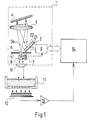
- the radiation source 1 of the spectrometer has been composed of light-emitting diodes, or LEDs.
- the radiation source 1 consists of a row of LEDs 2 which comprises a plurality of side-by-side LED semiconductor chips, or LED elements 21, 22, 23, ..., 26, which are all similar.
- the radiation source further comprises optical means for separating the desired wavelength range from the radiation produced by the LEDs, and means for maintaining the intensity of the radiation in the wavelength range constant or on desired level.
- Said optical means consist of optical pieces of equipment, such as lenses, mirrors, gratings, slits and beam dividers, the radiation produced by the LEDs being collected and dispersed to a spectrum with the aid of said means, and the radiation of the desired wavelength range being directed on an output slit or equivalent.
- the optical means in the spectrometer of Fig. 1 include a radiation-collecting lens 3, a reflecting grating 5 dispersing the radiation to a spectrum, and a stop 6 presenting an output slit 6.
- radiation-collecting component e.g. a concave mirror, and in place of the reflection grating one may use a transmission grating or a prism. These components may also be combined by using, for instance, a focussing reflector or transmission grating.
- the controllable radiation source 1 of the invention further comprises optical means and a detector 7 for observing and/or measuring the intensity of the outgoing radiation.
- the optical means employed in the spectrometer of Fig. 1 consist of a beam divider 8.
- the radiation source also comprises a driver and control means 9, to which the detector 7 has been connected.
- the driver and control means 9 is connected to the LED row 2, to each of its elements 21, 22, ..., 26. With the aid of the driver and control means 9, the desired LED element is selected.
- the desired wavelength range is directed on the output slit, this wavelength range depending on the location of the LED element 21, 22, ..., 26.
- Fig. 1 the output radiation passing through the exit slit 6 is rendered parallel with a lens 10, whereafter it is directed on the object of measurement, 11.
- a receiver 12 After the object of measurement, in the direction of propagation of the radiation, follows a receiver 12, in which capacity in measurements made on diffuse objects advantageously serves a wide-area radiometer.
- the electric signal from the receiver 12 is amplified in an amplifier 13 and fed to a calculation unit 14, and it is possibly displayed on a display provided in conjunction therewith.
- the driver and control unit 9 of the radiation source 1 may possibly also be controlled.
- At least the radiation source 1 is advantageous to devise at least the radiation source 1 to be an integral unit. It can be suitably shielded against ambience, for instance enclosed in a hermetically sealed housing, for improved reliability.
- the circuitry of the driver and control means 9 is presented in block diagram form in Fig. 3.
- the LED elements are connected to a selector means 16, such as a decoder, and this is connected to the calculating unit 14.
- the desired LED element, for instance the element 23, and the desired wavelength range of the output radiation from the radiation source are selected with the aid of the selector means 16.
- Part of the radiation obtained from the LED elements is picked up with the aid of the optical means 8 and carried to the detector 7.
- the detector 7 is connected with the controller 9a.
- the current control circuit 15 is governed by the controller 9a with the aid of the signal from the detector 7, in such manner that the output signal of the detector has constantly the desired magnitude, whereby the intensity of the output radiation also maintains the desired level.
- Fig. 2 illustrates the spectrum of the output radiation obtained by the procedure of the invention.
- the ordinates represent the radiation intensity I and the abscissae, the wavelength
- the radiation spectrum of a standard LED has the shape of a broad bell curve, L, Fig. 2A.
- the spectra of the radiation coming from, a radiation source 1 according to the invention are narrow bands of desired height, or ranges, S, Figs 2B-2E, within the range delimited by the bell curve L.
- the spectrometer of Fig. 1 and the radiation source therein employed operate in principle as follows.
- the driver and control means 9 selects and activates in the LED row 2 the first LED element 21.
- the radiation of the LED element is collected with the lens 3 and sent as a parallel beam to the reflection grating 4.
- the lens 3 further produces of the radiation reflected by the grating a spectrum on the stop 5. That part of the radiation (wavelength range ⁇ 1) passes through the output slit 6 which is determined by the location of the LED element 21 in the row and by the locations and dimensioning of the other optical means 3,4,6. From the lens 10) a parallel output radiation is obtained, striking the object of measurement 11.
- part of the output radiation is directed to strike the detector 7, and the signal representing the intensity that has been obtained is recorded with the driver and control means 9.
- the driver and control means adjusts the current going to the LED element 21 to have a value such that the signal obtained from the detector 7 rises to desired level, whereby the intensity of the output radiation also assumes the desired value, e.g. I0.
- the driver and control means 9 activates the LED element 22 and, after the output intensity has similarly been adjusted to required level, measurement takes place in the wavelength range ⁇ 2 (Fig. 2C).
- the driver and control means 9 activates all LED elements 21 ...
- the calculating unit 14 is electrically synchronized with the driver and control means 9 so that all results of measurement that have been recorded can be coordinated with the correct wavelength ranges ⁇ 1, ... ⁇ N .
- the optical means for collecting the radiation from the LED rows, for dispersing it to a spectrum and for directing the desired wavelength range on the output slit 6, comprising a lens 3 and a reflection grating 4 or equivalent.
- said optical means comprise a beam divider cube 17 and on the surface thereof a focussing transmission grating 18.
- the detector 7 for monitoring the intensity of the output radiation has been disposed in conjunction with the beam divider cube 17.
- the dividing interface 17a of the beam divider cube reflects to the detector 7 part of the radiation going through the beam divider cube to the output slit.
- In the capacity of output slit serves an optic fibre connector 19 to which an optic fibre 31 has been connected.
- the radiation source 1 with its LED row 2 is enclosed in a suitable housing 32.
- Fig. 5 depicts a compact spectrometer intended for reflection measurements and comprising both the transmitter of the radiation source and the receiver.
- the radiation source 1 is equivalent in its design with the radiation source of Fig. 4, and the same reference numerals are employed to indicate equivalent components.
- a receiver 33 In front of the radiation source 1, in the direction of propagation of the radiation, a receiver 33 has been disposed. This receiver consists of a beam divider 34 and a receiver detector 12. The output radiation is carried put from the device through an aperture 35.
- the object of measurement 36 which is a reflecting surface, is placed in front of the radiation beam coming from the spectrometer.
- the radiation reflected from the object of measurement 36 returns through the aperture 35 to the beam divider 34 of the receiver 33, from the dividing interface 34a of which the major part of the radiation is reflected to the receiver detector 12 and is detected.
- Both the radiation source 1 and the receiver 33 have in this case been integrated to constitute a single unit, which may be provided with a hermetically sealed housing 36 if required. In this way the reflection spectrometer can be made into a device usable in the field.
- the radiation from the spectrometer can be directed to strike the object of measurement 36 without any separate output optics, as has been set forth in the foregoing, or by using e.g. a standard lens optic system or a fibre-optic component.
- the LED row may be replaced with another type of radiation source row, as can be seen in Fig. 6.
- Fig. 6A presents, seen from the side, a LED row 2 comprising consecutively placed LED elements 21, 22, ..., 2N.
- the alternative radiation source row depicted in Fig. 6B comprises a number of LED elements or separate, encapsulated LEDs 21, 22 27, to each of them connected an optic fibre 41, 42, ..., 47 by its first end 41a, 42a, ..., 47a.
- the other ends 41b, 42b, ..., 47b of the optic fibres are arranged in a configuration such as is desired.
- the ends of the optic fibres are then close together and are thus equivalent e.g. to the LED row presented in the foregoing.
Landscapes
- Physics & Mathematics (AREA)
- Spectroscopy & Molecular Physics (AREA)
- General Physics & Mathematics (AREA)
- Health & Medical Sciences (AREA)
- Life Sciences & Earth Sciences (AREA)
- Chemical & Material Sciences (AREA)
- Analytical Chemistry (AREA)
- Biochemistry (AREA)
- General Health & Medical Sciences (AREA)
- Immunology (AREA)
- Pathology (AREA)
- Spectrometry And Color Measurement (AREA)
- Investigating Or Analysing Materials By Optical Means (AREA)
Claims (10)
- Verfahren zum Regeln einer Strahlungsquelle (1) mit einer Merhzahl von Leuchtdioden oder LEDs (21, 22, 23, ... 26);
wobei das Verfahren einen Schritt des wahlweisen Ansteuerns einer der LEDs zum Erzeugen einer Ausgangsstrahlung innerhalb eines ausgewählten Wellenlängenbereichs (Δλ₁, Δλ₂, Δλ₃,... ) aufweist;
gekennzeichnet durch die Schritte, nach denen der ausgewählte Wellenlängenbereich aus einem verhältnismässig breiten Wellenlängenbereich der Strahlung separiert wird, die von der einen LED emittiert wird, und dieser separierte Wellenlängenbereich zu einem Ausgangsspalt (6) oder dergleichen hin gerichtet wird, wobei das Separieren und das Richten mit Hilfe optischer Dispersionsmittel (3, 4, 5) durchgeführt werden, und der separierte Wellenlängenbereich von der Position der LED relativ zu den optischen Dispersionsmitteln (3, 4, 5) abhängt; wobei die Intensität der Strahlung in dem ausgewählten Wellenlängenbereich oder der Ausgangsstrahlung gemessen wird, und der durch die eine angesteuerte LED hindurchfliessende Strom in Antwort auf die gemessene Intensität derart gesteuert wird, dass diese gemessene Intensität geregelt oder konstant gehalten wird. - Verfahren nach Anspruch 1, dadurch gekennzeichnet, dass die Wellenlängenbereiche (Δλ₁, Δλ₂, Δλ₃, ... ) der Ausgangsstrahlung durch Aktivieren eines geeigneten LED-Elements (21, 22, 23, ... 26) aus der Mehrzahl von LEDs elektrisch ausgewählt werden.
- Regelbare Strahlungsquelle (1) zum Erzeugen einer Ausgangsstrahlung innerhalb eines ausgewählten Wellenlängenbereichs (Δλ₁, Δλ₂, Δλ₃, ... ) mit:
einer Mehrzahl von Leuchtdioden oder LEDs (21, 22, 23, ... 26);
einem Ausgangsspalt (6) oder dergleichen;
optischen Dispersionsmitteln (3, 4, 5), die in dem optischen Weg zwischen der Mehrzahl von Leuchtdioden und dem Ausgangsspalt angeordnet sind, wobei die optischen Dispersionsmittel zum Empfangen der Strahlung und zum Brechen der empfangenen Strahlung in eine Richtung hin ausgelegt sind, die von der Wellenlänge der empfangenen Strahlung abhängt; und einem Ansteuerungs- und Regelungsmittel (9) zum wahlweisen Ansteuern einer der LEDs;
dadurch gekennzeichnet,
dass die Leuchtdioden zueinander gleich sind und eine Strahlung in einem verhältnismässig breiten Wellenlängenbereich emittieren, aus welchem der ausgewählte Wellenlängenbereich durch die Position einer gesondert angesteuerten LED relativ zu dem optischen Dispersionselement bestimmt ist;
dass optische Mittel (8) derart angeordnet sind, dass ein Teil der Ausgangsstrahlung oder der Strahlung, die von dem optischen Dispersionselement zu dem Ausgangsspalt hin gebrochen wird, zu einem Strahlungsintensitätsdetektor (7) hin zum Messen der Intensität der Strahlung innerhalb des ausgewählten Wellenlängenbereichs gerichtet wird; und dass das Ansteuerungs- und Regelungsmittel (9) zum Ansteuern der ausgewählten LED in Antwort auf die von dem Strahlungsintensitätsdetektor detektierte Intensität ausgelegt ist, derart, dass die Intensität der Strahlung innerhalb des ausgewählten Wellenlängenbereichs, wie von dem Strahlungsintensitätsdetektor (7) detektiert, geregelt oder auf einem gewünschten Wert (I₀) gehalten wird. - Strahlungsquelle nach Anspruch 3, dadurch gekennzeichnet, dass die LED-Elemente (21, 22, 23, ..., 26) in einer LED-Reihe (2, 2′) angeordnet sind, und zusammengeschaltet sind und mit einer Stromsteuerungsschaltung (15) und einem Auswahlmittel (16) verbunden sind, mit dessen Hilfe das gewünschte LED-Element (z.B. 23) und der gewünschte Wellenlängenbereich (Δλ₃) der Ausgangsstrahlung der Strahlungsquelle ausgewählt werden, und die Stromsteuerungsschaltung (15) von einer Steuereinheit (9a) mit Hilfe des Signals von dem Detektor (7) derart gesteuert wird, dass die Intensität (I₀) der Ausgangsstrahlung kontinuierlich auf demselben Wert gehalten ist.
- Strahlungsquelle nach Anspruch 3 oder 4, dadurch gekennzeichnet, dass die optischen Mittel zum Empfangen und zum Zerlegen der von den LEDs erzeugten Strahlung und zum Richten des gewünschten Wellenlängenbereichs auf den Ausgangsspalt (6) hin ein fokusierendes Reflexions- oder Transmissionsgitter aufweisen.
- Strahlungsquelle nach Anspruch 3 oder 4, dadurch gekennzeichnet, dass die optischen Mittel zum Empfangen und zum Zerlegen der von den LEDs erzeugten Strahlung und zum Richten des gewünschten Wellenlängenbereichs auf den Ausgangsspalt (6) und auf den Detektor einen Strahlenteilerwürfel (17) und an dessen Oberfläche ein Transmissionsgitter (18) aufweisen.
- Strahlungsquelle nach Anspruch 6, dadurch gekennzeichnet, dass der Detektor (7) zum Überwachen der Intensität der Ausgangsstrahlung mit dem Strahlenteilerwürfel (17) verbunden angeordnet ist, so dass der Strahlenteilerwürfel auch als ein dem Detektor zugeordnetes optisches Mittel dient.
- Strahlungsquelle nach einem der vorangehenden Ansprüche 3 bis 7, zum Durchführen von Reflexions- und/oder Transmissionsmessungen, dadurch gekennzeichnet, dass die Strahlungsquelle (1) als integrierte Einheit (32) ausgebildet ist.
- Strahlungsquelle nach einem der vorangehenden Ansprüche 3 bis 7, dadurch gekennzeichnet, dass die Strahlungsquelle (1) mit einem Empfänger (33) integriert ist zum Bilden einer integrierten Einheit zum Durchführen von Reflexionsmessungen, welche Einheit vorteilhaft ein hermetisch abgedichtetes Gehäuse (37) umfasst.
- Strahlungsquelle nach einem der vorangehenden Ansprüche 3 bis 7, dadurch gekennzeichnet, dass die LED-Reihe (2') aus einer Mehrzahl von LED-Elementen oder gesondert eingekapselten LEDs (21, 22, ..., 27, Fig. 6B) besteht, an jede von denen eine optische Faser (41, 42, ..., 47) mit ihrem einen Ende (41a, 42a, ..., 47a) angeschlossen ist, und die zweiten Enden (41b, 42b, ..., 47b) in einer gewünschten Konfiguration angeordnet sind.
Applications Claiming Priority (3)
| Application Number | Priority Date | Filing Date | Title |
|---|---|---|---|
| FI872824 | 1987-06-25 | ||
| FI872824A FI77736C (fi) | 1987-06-25 | 1987-06-25 | Foerfarande foer reglering av straolkaella och reglerbar straolkaella. |
| PCT/FI1988/000103 WO1988010462A1 (en) | 1987-06-25 | 1988-06-23 | Procedure for controlling a radiation source and controllable radiation source |
Publications (2)
| Publication Number | Publication Date |
|---|---|
| EP0366696A1 EP0366696A1 (de) | 1990-05-09 |
| EP0366696B1 true EP0366696B1 (de) | 1994-11-23 |
Family
ID=8524727
Family Applications (1)
| Application Number | Title | Priority Date | Filing Date |
|---|---|---|---|
| EP88905853A Expired - Lifetime EP0366696B1 (de) | 1987-06-25 | 1988-06-23 | Verfahren zur steuerung einer strahlungsquelle und einer regelbaren strahlungsquelle |
Country Status (5)
| Country | Link |
|---|---|
| US (1) | US5029245A (de) |
| EP (1) | EP0366696B1 (de) |
| DE (1) | DE3852176T2 (de) |
| FI (1) | FI77736C (de) |
| WO (1) | WO1988010462A1 (de) |
Families Citing this family (83)
| Publication number | Priority date | Publication date | Assignee | Title |
|---|---|---|---|---|
| US5369286A (en) * | 1989-05-26 | 1994-11-29 | Ann F. Koo | Method and apparatus for measuring stress in a film applied to surface of a workpiece |
| GB8913800D0 (en) * | 1989-06-15 | 1989-08-02 | Secr Defence | Colour monitoring |
| JPH03269681A (ja) * | 1990-03-19 | 1991-12-02 | Sharp Corp | 画像認識装置 |
| WO1994015183A1 (en) * | 1991-06-28 | 1994-07-07 | Valtion Teknillinen Tutkimuskeskus | Radiation source |
| US5523582A (en) * | 1992-04-30 | 1996-06-04 | Ann F. Koo | Method and apparatus for measuring the curvature of wafers with a laser source selecting device |
| US5477322A (en) * | 1994-10-13 | 1995-12-19 | Nirsystems Incorporated | Spectrophotometer with light source in the form of a light emitting diode array |
| US5758644A (en) * | 1995-06-07 | 1998-06-02 | Masimo Corporation | Manual and automatic probe calibration |
| IT1280954B1 (it) * | 1995-10-05 | 1998-02-11 | Sorin Biomedica Cardio Spa | Procedimento e sistema per rilevare parametri chimico-fisici. |
| FI103074B1 (fi) * | 1996-07-17 | 1999-04-15 | Valtion Teknillinen | Spektrometri |
| EP1610115A3 (de) * | 1997-05-23 | 2010-03-03 | Becton, Dickinson and Company | Automatische mikrobiologische Testvorrichtung und Verfahren dafür |
| BR9809154B1 (pt) * | 1997-05-23 | 2012-09-04 | aparelho e sistema de teste microbiológico diagnóstico. | |
| JP3971844B2 (ja) | 1998-05-13 | 2007-09-05 | 株式会社キーエンス | 光学装置、光電スイッチ、ファイバ型光電スイッチおよび色識別センサ |
| DE69942522D1 (de) * | 1998-07-14 | 2010-08-05 | Us Government | Infrarotspektroskopie mit hohem durchsatz |
| US6483112B1 (en) | 1998-07-14 | 2002-11-19 | E. Neil Lewis | High-throughput infrared spectroscopy |
| US6310337B1 (en) | 1998-08-13 | 2001-10-30 | Joseph M. Chiapperi | Method of preselecting flashlamp voltages for assays |
| US6721585B1 (en) | 1998-10-15 | 2004-04-13 | Sensidyne, Inc. | Universal modular pulse oximeter probe for use with reusable and disposable patient attachment devices |
| USRE41912E1 (en) | 1998-10-15 | 2010-11-02 | Masimo Corporation | Reusable pulse oximeter probe and disposable bandage apparatus |
| US7245953B1 (en) | 1999-04-12 | 2007-07-17 | Masimo Corporation | Reusable pulse oximeter probe and disposable bandage apparatii |
| DE29901464U1 (de) * | 1999-01-28 | 2000-07-06 | J & M Analytische Mess- und Regeltechnik GmbH, 73431 Aalen | Kombinationslichtquelle und Analysesystem unter Verwendung derselben |
| US6690464B1 (en) | 1999-02-19 | 2004-02-10 | Spectral Dimensions, Inc. | High-volume on-line spectroscopic composition testing of manufactured pharmaceutical dosage units |
| US6403947B1 (en) | 1999-03-18 | 2002-06-11 | Cambridge Research & Instrumentation Inc. | High-efficiency multiple probe imaging system |
| US7123844B2 (en) * | 1999-04-06 | 2006-10-17 | Myrick Michael L | Optical computational system |
| US6529276B1 (en) | 1999-04-06 | 2003-03-04 | University Of South Carolina | Optical computational system |
| US6259430B1 (en) | 1999-06-25 | 2001-07-10 | Sarnoff Corporation | Color display |
| US6761959B1 (en) * | 1999-07-08 | 2004-07-13 | Flex Products, Inc. | Diffractive surfaces with color shifting backgrounds |
| US20070195392A1 (en) * | 1999-07-08 | 2007-08-23 | Jds Uniphase Corporation | Adhesive Chromagram And Method Of Forming Thereof |
| US7667895B2 (en) * | 1999-07-08 | 2010-02-23 | Jds Uniphase Corporation | Patterned structures with optically variable effects |
| US6373568B1 (en) | 1999-08-06 | 2002-04-16 | Cambridge Research & Instrumentation, Inc. | Spectral imaging system |
| US6750964B2 (en) * | 1999-08-06 | 2004-06-15 | Cambridge Research And Instrumentation, Inc. | Spectral imaging methods and systems |
| EP1210584A1 (de) * | 1999-08-19 | 2002-06-05 | Washington State University Research Foundation | Methoden zur bestimmung des physiologischen zustands einer pflanze |
| US6950687B2 (en) | 1999-12-09 | 2005-09-27 | Masimo Corporation | Isolation and communication element for a resposable pulse oximetry sensor |
| JP2003520986A (ja) * | 2000-01-21 | 2003-07-08 | フレックス プロダクツ インコーポレイテッド | 光学変調セキュリティーデバイス |
| WO2001061293A1 (en) * | 2000-02-18 | 2001-08-23 | Spectral Dimensions, Inc. | Multi-source spectrometry |
| US7138156B1 (en) | 2000-09-26 | 2006-11-21 | Myrick Michael L | Filter design algorithm for multi-variate optical computing |
| JP4685229B2 (ja) * | 2000-10-31 | 2011-05-18 | オリンパス株式会社 | レーザ顕微鏡 |
| US6689999B2 (en) * | 2001-06-01 | 2004-02-10 | Schott-Fostec, Llc | Illumination apparatus utilizing light emitting diodes |
| US6930773B2 (en) * | 2001-08-23 | 2005-08-16 | Cambridge Research And Instrumentation, Inc. | Spectral imaging |
| US6825930B2 (en) * | 2002-06-04 | 2004-11-30 | Cambridge Research And Instrumentation, Inc. | Multispectral imaging system |
| US7251587B2 (en) * | 2002-08-12 | 2007-07-31 | System To Asic, Inc. | Flexible scanning and sensing platform |
| US20040188594A1 (en) * | 2003-05-01 | 2004-09-30 | Brown Steven W. | Spectrally tunable solid-state light source |
| US7500950B2 (en) | 2003-07-25 | 2009-03-10 | Masimo Corporation | Multipurpose sensor port |
| US20050030192A1 (en) * | 2003-08-08 | 2005-02-10 | Weaver James T. | Power supply for LED airfield lighting |
| US7321791B2 (en) | 2003-09-23 | 2008-01-22 | Cambridge Research And Instrumentation, Inc. | Spectral imaging of deep tissue |
| US8634607B2 (en) | 2003-09-23 | 2014-01-21 | Cambridge Research & Instrumentation, Inc. | Spectral imaging of biological samples |
| US7324569B2 (en) * | 2004-09-29 | 2008-01-29 | Axsun Technologies, Inc. | Method and system for spectral stitching of tunable semiconductor sources |
| WO2006081547A1 (en) | 2005-01-27 | 2006-08-03 | Cambridge Research And Instrumentation, Inc. | Classifying image features |
| US7499165B2 (en) * | 2005-03-15 | 2009-03-03 | Electronic Design To Market, Inc. | System of measuring light transmission and/or reflection |
| DE102005022175A1 (de) * | 2005-05-13 | 2006-12-21 | Carl Zeiss Jena Gmbh | Multispektrale Beleuchtungseinheit |
| US7279678B2 (en) * | 2005-08-15 | 2007-10-09 | Schlumber Technology Corporation | Method and apparatus for composition analysis in a logging environment |
| CA2564764C (en) * | 2005-10-25 | 2014-05-13 | Jds Uniphase Corporation | Patterned optical structures with enhanced security feature |
| WO2007061436A1 (en) * | 2005-11-28 | 2007-05-31 | University Of South Carolina | Self calibration methods for optical analysis system |
| US10188348B2 (en) | 2006-06-05 | 2019-01-29 | Masimo Corporation | Parameter upgrade system |
| US9170154B2 (en) | 2006-06-26 | 2015-10-27 | Halliburton Energy Services, Inc. | Data validation and classification in optical analysis systems |
| US8255026B1 (en) | 2006-10-12 | 2012-08-28 | Masimo Corporation, Inc. | Patient monitor capable of monitoring the quality of attached probes and accessories |
| US7880626B2 (en) | 2006-10-12 | 2011-02-01 | Masimo Corporation | System and method for monitoring the life of a physiological sensor |
| EP2078187A2 (de) * | 2006-11-02 | 2009-07-15 | University of South Carolina | Optisches multianalyt-datenverarbeitungssystem |
| US7651268B2 (en) * | 2007-02-23 | 2010-01-26 | Cao Group, Inc. | Method and testing equipment for LEDs and laser diodes |
| US8213006B2 (en) * | 2007-03-30 | 2012-07-03 | Halliburton Energy Services, Inc. | Multi-analyte optical computing system |
| WO2008121692A1 (en) * | 2007-03-30 | 2008-10-09 | University Of South Carolina | Tablet analysis and measurement system |
| EP2140238B1 (de) * | 2007-03-30 | 2020-11-11 | Ometric Corporation | Messsysteme und -verfahren für inline-verfahren |
| US8519358B2 (en) | 2008-02-05 | 2013-08-27 | Pocared Diagnostics Ltd. | System for conducting the identification of bacteria in biological samples |
| US8212213B2 (en) * | 2008-04-07 | 2012-07-03 | Halliburton Energy Services, Inc. | Chemically-selective detector and methods relating thereto |
| US8406859B2 (en) | 2008-08-10 | 2013-03-26 | Board Of Regents, The University Of Texas System | Digital light processing hyperspectral imaging apparatus |
| US8101906B2 (en) | 2008-10-08 | 2012-01-24 | Applied Materials, Inc. | Method and apparatus for calibrating optical path degradation useful for decoupled plasma nitridation chambers |
| US8309897B2 (en) * | 2009-02-06 | 2012-11-13 | Pocared Diagnostics Ltd. | Optical measurement arrangement |
| US8571619B2 (en) | 2009-05-20 | 2013-10-29 | Masimo Corporation | Hemoglobin display and patient treatment |
| US10288632B2 (en) | 2009-09-21 | 2019-05-14 | Pocared Diagnostics Ltd. | System for conducting the identification of bacteria in biological samples |
| DE102009046831B4 (de) * | 2009-11-18 | 2015-02-12 | Fraunhofer-Gesellschaft zur Förderung der angewandten Forschung e.V. | Strahlungserzeugungsvorrichtung zum Erzeugen einer elektromagnetischen Strahlung mit einer einstellbaren spektralen Zusammensetzung und Verfahren zur Herstellung derselben |
| JP5796275B2 (ja) * | 2010-06-02 | 2015-10-21 | セイコーエプソン株式会社 | 分光測定器 |
| JP5254308B2 (ja) * | 2010-12-27 | 2013-08-07 | 東京エレクトロン株式会社 | 液処理装置、液処理方法及びその液処理方法を実行させるためのプログラムを記録した記録媒体 |
| US8891087B2 (en) * | 2011-06-01 | 2014-11-18 | Digital Light Innovations | System and method for hyperspectral imaging |
| US20130148107A1 (en) * | 2011-12-07 | 2013-06-13 | Honeywell Asca Inc. | Multi-source sensor for online characterization of web products and related system and method |
| JP5842652B2 (ja) * | 2012-02-08 | 2016-01-13 | 株式会社島津製作所 | 波長可変単色光光源 |
| US9297749B2 (en) | 2012-03-27 | 2016-03-29 | Innovative Science Tools, Inc. | Optical analyzer for identification of materials using transmission spectroscopy |
| US8859969B2 (en) | 2012-03-27 | 2014-10-14 | Innovative Science Tools, Inc. | Optical analyzer for identification of materials using reflectance spectroscopy |
| JP2016501372A (ja) | 2012-12-07 | 2016-01-18 | エスピースリーエイチ | 熱機関において流体を分析するための車載装置および方法 |
| WO2014093463A1 (en) | 2012-12-11 | 2014-06-19 | Pocared Diagnostics Ltd. | Optics cup with curved bottom |
| US9182278B2 (en) * | 2013-03-14 | 2015-11-10 | Sciaps, Inc. | Wide spectral range spectrometer |
| JP6774174B2 (ja) * | 2015-10-08 | 2020-10-21 | 株式会社キーエンス | 光電スイッチ |
| WO2018020535A1 (ja) * | 2016-07-25 | 2018-02-01 | 株式会社島津製作所 | 光度計 |
| CN112611456B (zh) * | 2019-09-18 | 2025-04-29 | 深圳市中光工业技术研究院 | 光谱仪 |
| EP4443118A1 (de) * | 2023-04-04 | 2024-10-09 | F. Hoffmann-La Roche AG | Lichtquelle zur erzeugung von beleuchtungslicht |
| DE102024109739A1 (de) * | 2024-04-08 | 2025-10-09 | Ams-Osram International Gmbh | Uv-reaktor mit mischvorrichtung |
Family Cites Families (11)
| Publication number | Priority date | Publication date | Assignee | Title |
|---|---|---|---|---|
| US4022531A (en) * | 1973-10-17 | 1977-05-10 | U.S. Philips Corporation | Monochromator |
| JPS5182630A (de) * | 1975-01-16 | 1976-07-20 | Minolta Camera Kk | |
| JPS54143109A (en) * | 1978-04-28 | 1979-11-08 | Hitachi Ltd | Optical information device |
| US4455562A (en) * | 1981-08-14 | 1984-06-19 | Pitney Bowes Inc. | Control of a light emitting diode array |
| US4443695A (en) * | 1980-01-25 | 1984-04-17 | Canon Kabushiki Kaisha | Apparatus for controlling the quantity of light |
| ES492136A0 (es) * | 1980-06-04 | 1980-12-16 | Standard Electrica Sa | Un procedimiento de proteccion de la fuente luminosa de los transmisores opticos |
| HU186069B (en) * | 1982-06-09 | 1985-05-28 | Koezponti Elelmiszeripari | Spectrophotometer operating on discrete wave-lengths |
| US4449821A (en) * | 1982-07-14 | 1984-05-22 | E. I. Du Pont De Nemours And Company | Process colorimeter |
| HU187188B (en) * | 1982-11-25 | 1985-11-28 | Koezponti Elelmiszeripari | Device for generating radiation of controllable spectral structure |
| NL8400380A (nl) * | 1984-02-07 | 1985-09-02 | Optische Ind De Oude Delft Nv | Inrichting voor het detecteren van kleurverschillen. |
| US4790654A (en) * | 1987-07-17 | 1988-12-13 | Trw Inc. | Spectral filter |
-
1987
- 1987-06-25 FI FI872824A patent/FI77736C/fi not_active IP Right Cessation
-
1988
- 1988-06-23 WO PCT/FI1988/000103 patent/WO1988010462A1/en not_active Ceased
- 1988-06-23 US US07/457,694 patent/US5029245A/en not_active Expired - Lifetime
- 1988-06-23 EP EP88905853A patent/EP0366696B1/de not_active Expired - Lifetime
- 1988-06-23 DE DE3852176T patent/DE3852176T2/de not_active Expired - Fee Related
Also Published As
| Publication number | Publication date |
|---|---|
| EP0366696A1 (de) | 1990-05-09 |
| FI77736C (fi) | 1989-04-10 |
| DE3852176D1 (de) | 1995-01-05 |
| WO1988010462A1 (en) | 1988-12-29 |
| US5029245A (en) | 1991-07-02 |
| FI77736B (fi) | 1988-12-30 |
| DE3852176T2 (de) | 1995-06-22 |
| FI872824A0 (fi) | 1987-06-25 |
Similar Documents
| Publication | Publication Date | Title |
|---|---|---|
| EP0366696B1 (de) | Verfahren zur steuerung einer strahlungsquelle und einer regelbaren strahlungsquelle | |
| CA2261139C (en) | Spectrometer | |
| US5026160A (en) | Monolithic optical programmable spectrograph (MOPS) | |
| KR100832161B1 (ko) | 광학 피드백을 위한 광감지기 구성을 구비하는 led조명 기구 | |
| US4060327A (en) | Wide band grating spectrometer | |
| US5818586A (en) | Miniaturized fabry-perot spectrometer for optical analysis | |
| US5475221A (en) | Optical spectrometer using light emitting diode array | |
| US6529276B1 (en) | Optical computational system | |
| EP0413939B1 (de) | Verbessertes Gitterspektrometer | |
| US20100007877A1 (en) | Narrow-band spectrometric Measurements | |
| JPH10232164A (ja) | バンドパスフォトン検出器 | |
| WO1995010759A1 (en) | Spectral wavelength discrimination system and method for using | |
| US4630925A (en) | Compact temporal spectral photometer | |
| EP1111333A1 (de) | Lichtquellevorrichtung,Spektroskop mit dieser Vorrichtung und Schichfehickesensor | |
| CN113884199A (zh) | 一种用于mems法珀腔芯片的标定装置及其标定方法 | |
| US4722606A (en) | Analytical photometer, in particular multi-channel, applied to a centrifugal system adapted to perform practically simultaneous determination of the presence of different substances in a certain number of samples | |
| EP0063126B1 (de) | Optische übertragungssysteme | |
| WO2003087786A1 (en) | Method and apparatus for gas detection | |
| Keranen et al. | Semiconductor emitter based 32-channel spectrophotometer module for real-time process measurements | |
| Malinen et al. | Thirty-two-channel LED array spectrometer module with compact optomechanical construction | |
| FI89631B (fi) | Straolkaella och excitationsanordning foer den | |
| WO1994015183A1 (en) | Radiation source | |
| JPS58165022A (ja) | 分光光度計 | |
| Malinen et al. | LED-based spectrometer modules for handheld sensors and online process monitoring | |
| CN120594458A (zh) | 一种光谱检测器及粒子分析仪 |
Legal Events
| Date | Code | Title | Description |
|---|---|---|---|
| PUAI | Public reference made under article 153(3) epc to a published international application that has entered the european phase |
Free format text: ORIGINAL CODE: 0009012 |
|
| 17P | Request for examination filed |
Effective date: 19891222 |
|
| AK | Designated contracting states |
Kind code of ref document: A1 Designated state(s): BE DE FR GB IT NL SE |
|
| 17Q | First examination report despatched |
Effective date: 19930121 |
|
| GRAA | (expected) grant |
Free format text: ORIGINAL CODE: 0009210 |
|
| AK | Designated contracting states |
Kind code of ref document: B1 Designated state(s): BE DE FR GB IT NL SE |
|
| ITF | It: translation for a ep patent filed | ||
| REF | Corresponds to: |
Ref document number: 3852176 Country of ref document: DE Date of ref document: 19950105 |
|
| ET | Fr: translation filed | ||
| EAL | Se: european patent in force in sweden |
Ref document number: 88905853.3 |
|
| PLBE | No opposition filed within time limit |
Free format text: ORIGINAL CODE: 0009261 |
|
| STAA | Information on the status of an ep patent application or granted ep patent |
Free format text: STATUS: NO OPPOSITION FILED WITHIN TIME LIMIT |
|
| 26N | No opposition filed | ||
| REG | Reference to a national code |
Ref country code: GB Ref legal event code: IF02 |
|
| PGFP | Annual fee paid to national office [announced via postgrant information from national office to epo] |
Ref country code: FR Payment date: 20050512 Year of fee payment: 18 |
|
| PGFP | Annual fee paid to national office [announced via postgrant information from national office to epo] |
Ref country code: GB Payment date: 20050516 Year of fee payment: 18 |
|
| PGFP | Annual fee paid to national office [announced via postgrant information from national office to epo] |
Ref country code: NL Payment date: 20050517 Year of fee payment: 18 |
|
| PGFP | Annual fee paid to national office [announced via postgrant information from national office to epo] |
Ref country code: SE Payment date: 20050519 Year of fee payment: 18 |
|
| PGFP | Annual fee paid to national office [announced via postgrant information from national office to epo] |
Ref country code: DE Payment date: 20050520 Year of fee payment: 18 |
|
| PGFP | Annual fee paid to national office [announced via postgrant information from national office to epo] |
Ref country code: BE Payment date: 20050606 Year of fee payment: 18 |
|
| PG25 | Lapsed in a contracting state [announced via postgrant information from national office to epo] |
Ref country code: GB Free format text: LAPSE BECAUSE OF NON-PAYMENT OF DUE FEES Effective date: 20060623 |
|
| PG25 | Lapsed in a contracting state [announced via postgrant information from national office to epo] |
Ref country code: SE Free format text: LAPSE BECAUSE OF NON-PAYMENT OF DUE FEES Effective date: 20060624 |
|
| PG25 | Lapsed in a contracting state [announced via postgrant information from national office to epo] |
Ref country code: BE Free format text: LAPSE BECAUSE OF NON-PAYMENT OF DUE FEES Effective date: 20060630 |
|
| PGFP | Annual fee paid to national office [announced via postgrant information from national office to epo] |
Ref country code: IT Payment date: 20060630 Year of fee payment: 19 |
|
| PG25 | Lapsed in a contracting state [announced via postgrant information from national office to epo] |
Ref country code: NL Free format text: LAPSE BECAUSE OF NON-PAYMENT OF DUE FEES Effective date: 20070101 |
|
| PG25 | Lapsed in a contracting state [announced via postgrant information from national office to epo] |
Ref country code: DE Free format text: LAPSE BECAUSE OF NON-PAYMENT OF DUE FEES Effective date: 20070103 |
|
| EUG | Se: european patent has lapsed | ||
| GBPC | Gb: european patent ceased through non-payment of renewal fee |
Effective date: 20060623 |
|
| NLV4 | Nl: lapsed or anulled due to non-payment of the annual fee |
Effective date: 20070101 |
|
| REG | Reference to a national code |
Ref country code: FR Ref legal event code: ST Effective date: 20070228 |
|
| BERE | Be: lapsed |
Owner name: *VALTION TEKNILLINEN TUTKIMUSKESKUS Effective date: 20060630 |
|
| PG25 | Lapsed in a contracting state [announced via postgrant information from national office to epo] |
Ref country code: FR Free format text: LAPSE BECAUSE OF NON-PAYMENT OF DUE FEES Effective date: 20060630 |
|
| PG25 | Lapsed in a contracting state [announced via postgrant information from national office to epo] |
Ref country code: IT Free format text: LAPSE BECAUSE OF NON-PAYMENT OF DUE FEES Effective date: 20070623 |