EP0366787B1 - Procede et appareil de production de filaments de verre creux - Google Patents
Procede et appareil de production de filaments de verre creux Download PDFInfo
- Publication number
- EP0366787B1 EP0366787B1 EP89907028A EP89907028A EP0366787B1 EP 0366787 B1 EP0366787 B1 EP 0366787B1 EP 89907028 A EP89907028 A EP 89907028A EP 89907028 A EP89907028 A EP 89907028A EP 0366787 B1 EP0366787 B1 EP 0366787B1
- Authority
- EP
- European Patent Office
- Prior art keywords
- tubular member
- stream
- passageway
- feeder
- discharge wall
- Prior art date
- Legal status (The legal status is an assumption and is not a legal conclusion. Google has not performed a legal analysis and makes no representation as to the accuracy of the status listed.)
- Expired - Lifetime
Links
- 239000011521 glass Substances 0.000 title claims abstract description 9
- 238000000034 method Methods 0.000 title claims description 7
- 238000004519 manufacturing process Methods 0.000 claims abstract description 8
- 239000011800 void material Substances 0.000 claims abstract description 8
- 239000006060 molten glass Substances 0.000 claims description 18
- 239000012768 molten material Substances 0.000 claims description 8
- 239000000463 material Substances 0.000 claims description 4
- 229910052500 inorganic mineral Inorganic materials 0.000 claims description 2
- 239000011707 mineral Substances 0.000 claims description 2
- 229910010272 inorganic material Inorganic materials 0.000 claims 2
- 239000011147 inorganic material Substances 0.000 claims 2
- 230000000712 assembly Effects 0.000 abstract description 7
- 238000000429 assembly Methods 0.000 abstract description 7
- 239000000835 fiber Substances 0.000 abstract description 2
- 239000003570 air Substances 0.000 description 4
- 239000012080 ambient air Substances 0.000 description 3
- 239000012510 hollow fiber Substances 0.000 description 3
- 230000002238 attenuated effect Effects 0.000 description 2
- BASFCYQUMIYNBI-UHFFFAOYSA-N platinum Chemical compound [Pt] BASFCYQUMIYNBI-UHFFFAOYSA-N 0.000 description 2
- 229910001260 Pt alloy Inorganic materials 0.000 description 1
- 229910000629 Rh alloy Inorganic materials 0.000 description 1
- 239000011248 coating agent Substances 0.000 description 1
- 238000000576 coating method Methods 0.000 description 1
- 239000003365 glass fiber Substances 0.000 description 1
- 230000037361 pathway Effects 0.000 description 1
- 239000010970 precious metal Substances 0.000 description 1
- 238000004513 sizing Methods 0.000 description 1
- 239000007787 solid Substances 0.000 description 1
- 239000004753 textile Substances 0.000 description 1
Images

Classifications
-
- D—TEXTILES; PAPER
- D01—NATURAL OR MAN-MADE THREADS OR FIBRES; SPINNING
- D01D—MECHANICAL METHODS OR APPARATUS IN THE MANUFACTURE OF ARTIFICIAL FILAMENTS, THREADS, FIBRES, BRISTLES OR RIBBONS
- D01D5/00—Formation of filaments, threads, or the like
- D01D5/24—Formation of filaments, threads, or the like with a hollow structure; Spinnerette packs therefor
-
- C—CHEMISTRY; METALLURGY
- C03—GLASS; MINERAL OR SLAG WOOL
- C03B—MANUFACTURE, SHAPING, OR SUPPLEMENTARY PROCESSES
- C03B37/00—Manufacture or treatment of flakes, fibres, or filaments from softened glass, minerals, or slags
- C03B37/01—Manufacture of glass fibres or filaments
- C03B37/02—Manufacture of glass fibres or filaments by drawing or extruding, e.g. direct drawing of molten glass from nozzles; Cooling fins therefor
- C03B37/022—Manufacture of glass fibres or filaments by drawing or extruding, e.g. direct drawing of molten glass from nozzles; Cooling fins therefor from molten glass in which the resultant product consists of different sorts of glass or is characterised by shape, e.g. hollow fibres, undulated fibres, fibres presenting a rough surface
-
- C—CHEMISTRY; METALLURGY
- C03—GLASS; MINERAL OR SLAG WOOL
- C03B—MANUFACTURE, SHAPING, OR SUPPLEMENTARY PROCESSES
- C03B37/00—Manufacture or treatment of flakes, fibres, or filaments from softened glass, minerals, or slags
- C03B37/08—Bushings, e.g. construction, bushing reinforcement means; Spinnerettes; Nozzles; Nozzle plates
- C03B37/081—Indirect-melting bushings
-
- C—CHEMISTRY; METALLURGY
- C03—GLASS; MINERAL OR SLAG WOOL
- C03B—MANUFACTURE, SHAPING, OR SUPPLEMENTARY PROCESSES
- C03B37/00—Manufacture or treatment of flakes, fibres, or filaments from softened glass, minerals, or slags
- C03B37/08—Bushings, e.g. construction, bushing reinforcement means; Spinnerettes; Nozzles; Nozzle plates
- C03B37/083—Nozzles; Bushing nozzle plates
-
- Y—GENERAL TAGGING OF NEW TECHNOLOGICAL DEVELOPMENTS; GENERAL TAGGING OF CROSS-SECTIONAL TECHNOLOGIES SPANNING OVER SEVERAL SECTIONS OF THE IPC; TECHNICAL SUBJECTS COVERED BY FORMER USPC CROSS-REFERENCE ART COLLECTIONS [XRACs] AND DIGESTS
- Y10—TECHNICAL SUBJECTS COVERED BY FORMER USPC
- Y10S—TECHNICAL SUBJECTS COVERED BY FORMER USPC CROSS-REFERENCE ART COLLECTIONS [XRACs] AND DIGESTS
- Y10S425/00—Plastic article or earthenware shaping or treating: apparatus
- Y10S425/217—Spinnerette forming conjugate, composite or hollow filaments
Definitions
- the invention disclosed herein relates to a tip assembly, a feeder and a method for the production of hollow glass filaments.
- Glass filaments usually have a solid cross-section. There are, however, instances where hollow filaments would be preferred, since substantially the same rigidity can be achieved with reduced weight by employing hollow filaments.
- U.S. Patent No. 2,269,459 discloses flame drawing a preformed glass tube into a hollow filament.
- U.S. Patent No.'s 4,698,082 and 4,704,149 disclose systems for forming hollow filaments wherein a gas supply tube is positioned in each tip of the feeder to concomitantly supply an annular stream of molten glass and a gas in the interior thereof to form a hollow filament.
- the gas supply tubes are connected to a header or headers located above the pool of molten glass.
- the gas supply tubes are long and subject to various distorting forces.
- Various intricate systems for attaching the gas supply tubes to or at the feeder tips are disclosed, but such designs are rather complex and require a substantial amount of precious metal to be used.
- the present invention provides a tip assembly, a feeder and a method for producing hollow filaments wherein the stream defining tips are adapted to move the gas from the forming zone into the interior of the forming cone to produce such filaments.
- This invention pertains to a tip assembly according to Claim 1, a feeder according to Claim 9 and methods according to Claim 20 and 22, all the production of hollow glass filaments.
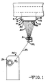
- feeder 10 which is comprised of an orificed bottom or discharge wall 14 and other sections such as containment or sidewalls 12 and end walls 13, is adapted to provide a plurality of streams 18 of molten inorganic or mineral material, such as glass, through a plurality of tip assemblies 30.
- Feeder 10 which depends from and receives a flow of molten glass from forehearth 5, Is electrically energized, including discharge wall 14, via terminals 16 attached to a suitable source of electrical energy (not shown) to heat the molten glass therein as is known in the art.
- Feeder 10, including tip assembly 30, may be fabricated from any suitable material, such as the platinum/rhodium alloys known in the art.
- terminals 16 are joined to end walls 13, but terminals 16 may extend outwardly from bottom wall 14 if desired.
- the streams 18 of molten glass having a void therein are attenuated into continuous hollow filaments 20 through the action of winder 26, or any other suitable means.
- the filament forming region can be cooled by any suitable means (not shown), for example finshields or forced air convection as is known in the art.
- Size applicator means 21 provides a coating or sizing material to the surface of the filaments 20 which advance to gathering shoe or means 22 to be collected as an advancing strand or bundle 23 as is known in the art. Strand 23 is then wound into package 24 upon a collet on winder 26.
- tip assemblies 30 are located in orifices 15 in discharge wall 14, similar to conventional tips.
- tip assemblies 30 depend from discharge wall 14, and according to the principles of this invention, the tip assemblies are adapted to move or draw the gas or ambient air immediately surrounding the tips 30 into the conical streams 18 of molten material to produce a continuous void 19 therein to produce hollow filaments 20.
- the gas is drawn into the interior of the cone 18 by the fact that the internal pressure of the molten glass at that location is sub-atmospheric due to, among other things, the attenuation of the cone 18 into a filament 20. That is, no outside source of pressurized air is needed to produce the hollow configuration.
- the present invention can be adapted to be utilized in conjunction with a pressurized system as will be discussed later herein.
- Tip assembly 30 is comprised of first tubular member 32 and second tubular member 42, which is located within bore or passageway 36 of first member 32.
- one end of member 42 is open to ambient air pressure immediately surrounding the tips 30, that is immediately adjacent discharge wall 14, and the other end of member 42 is located at or close to the tip exit.
- air in the forming region or zone is aspirated through passageway 44 of second member 42 into the cone 18 being attenuated into a filament 20, thereby forming a hollow filament 20.
- first tubular member 32 has a sleeve or wall segment 34 having an aperture 35 located intermediate shoulder 38 and distal end 39.
- First end 48 of second tubular member 42 is attached to sleeve segment 34 at aperture 35.
- inlet 45 of passageway 44 of second member 42 is in communication with the region immediately adjacent to the exterior of first member 32.
- Distal end 49 of second member 42 is concentrically located within the bore 36 of first member 32, and distal end 49 of second member 42, and accordingly outlet 46 of passageway 44, is located slightly below the distal end 39 of first member 32. It is to be understood, however, that other orientations may be acceptable.
- bore 36 of first member 32 may be of a non-circular configuration to enable the production of non-circular filaments having a continuous void centrally or non-centrally therein, as desired.
- second tubular member 42 is “L” shaped (inverted) and is attached to sleeve 34 at one location.
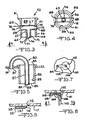
- the design of tip assembly 53 shown in FIGURES 3 and 4 incorporates a "T" shaped second tubular member 65 attached within first tubular member 55 at a plurality of locations.
- Sleeve or wall 56 of first member 55 contains opposed apertures 57 and 58 which are adapted to receive ends 68 and 69 of beam 67 of second member 65. Apertures 57 and 58 are located intermediate first end 61 and distal end 62 of sleeve 56. Projection 71 of second member 65 extends from beam 67 substantially concentrically, downwardly through bore 59 of first member 55. Distal end 72 of projection 71 is located at distal end 62 of first member 55. Thus, the gas of the region immediately below the discharge wall and surrounding first member 55 will be drawn into inlets 75 and 76 of passageway 74 of second member 65 and exhausted at outlet 77 thereof at distal end 72 according to the principles of this invention.
- Tip assembly 80 is comprised of second tubular member 87 located within the bore 83 of first tubular member 82 with the distal end 92 of second member 87 being located, similar to the previous designs, at distal end 85 of first member 82.
- second tubular member 87 and thus passageway 89 thereof does not penetrate the wall or sleeve of first member 82.
- second member is "J" shaped (inverted) such that second member extends upwardly over first end or shoulder 84 of first member 82 and then arcuately downward a distance sufficient such that inlet end 91 of second member 87 is located at or below the exterior surface of discharge wall 14.
- second member is suitably attached to discharge wall 14, and the gas of the region immediately below the discharge wall is moved into the conical stream of molten glass to form a hollow filament.
- FIGURES 6 and 7 set-fourth a hollow fiber forming system for "tipless" feeders, that is feeders having no stream defining tips depending therefrom.
- discharge wall 101 contains a plurality of stream defining orifices 102 (only one orifice shown for convenience) through which the molten glass exits for attenuation into filaments.
- Conduit 104 is attached to discharge wall 101 and is oriented such that first or inlet end 105 is in communication with the gas in the forming zone and second or outlet end 106 is positioned in the conical stream of molten glass 109 to permit the gas of the forming zone to be aspirated through passageway 108 into stream 109 to produce hollow fibers or filaments.
- Conduit 104 is "U" shaped (inverted) and oriented such that outlet end 106, as well as the inlet end, are oriented substantially parallel to discharge wall 101 or perpendicular to the axis of orifice 102 and stream 109.
- FIGURE 8 depicts another "tipless" design wherein a substantially straight conduit 114 extends partially into the cone of molten glass. As shown inlet end 115 of conduit 114 is attached to the exterior of discharge wall 111 adjacent stream defining orifice 112. Outlet end 116 is positioned centrally below orifice 112 and is beveled to reduce the tendency of molten glass to fill passageway 118 of conduit 114 which permits the ambient air of the forming zone to be aspirated into the molten stream to form hollow filaments.
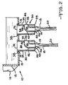
- FIGURE 9 depicts a hollow fiber forming system wherein gas, such as air, at predetermined elevated and controlled pressure is injected into the molten streams from a region immediately below the discharge wall to form such filaments.
- gas such as air
- Feeder 130 is comprised, similar to FIGURE 2, of containment walls 132 and discharge wall 134 which has a plurality of tip assemblies 140 positioned in orifices 135 in wall 134.
- a plate 137, spaced from discharge wall 134 and joined to containment walls 132 forms a chamber 139 which is connected to a source of pressurized gas via piping 158 and pressure regulator means 160.
- First tubular member 142 is joined to and extends from discharge wall 134 through apertures 138 in plate 137. As shown, distal end 145 of first member 142 extends below or beyond plate 137, although end 145 may be flush with the exterior of plate 137, if desired.
- Second tubular member 150 is positioned within bore 146 of first member 142 and inlet end 152 thereof is attached to wall 144 of aperture 148 of first member 142. Distal end 153 of second member 150 is positioned below distal end 145 to direct the gas into the filament forming cone of molten glass. Thus, passageway 155 of second member provides a pathway for the gas in chamber 139 to enter the forming cone of molten glass to form hollow filaments according to the principles of the present invention.
- feeder/tip assemblies of the present invention can be utilized to form discontinuous as well as the continuous filaments if desired.
- the invention disclosed herein is readily applicable to the glass fiber forming industry.
Landscapes
- Engineering & Computer Science (AREA)
- Chemical & Material Sciences (AREA)
- Materials Engineering (AREA)
- Geochemistry & Mineralogy (AREA)
- Manufacturing & Machinery (AREA)
- General Life Sciences & Earth Sciences (AREA)
- Life Sciences & Earth Sciences (AREA)
- Organic Chemistry (AREA)
- Mechanical Engineering (AREA)
- Textile Engineering (AREA)
- Spinning Methods And Devices For Manufacturing Artificial Fibers (AREA)
- Inorganic Fibers (AREA)
- Manufacture, Treatment Of Glass Fibers (AREA)
Abstract
Claims (23)
- Ensemble formant bec (30) destiné à être utilisé dans un dispositif d'alimentation (10) pour la production de filaments de verre creux (20), comportant :
un premier organe tubulaire (32) adapté pour être fixé à une paroi de déchargement (14) du dispositif d'alimentation (10) et pour recevoir un écoulement de verre fondu à travers lui, et
un second organe tubulaire (42) positionné à l'intérieur du premier organe tubulaire (32), le second organe tubulaire (42) possédant un passage (44) en communication avec la zone située au voisinage immédiat de l'extérieur du premier organe tubulaire (32) pour permettre au gaz de la zone de passer de cette zone par l'intermédiaire du passage (44) du second organe tubulaire (42) dans l'écoulement de verre fondu, afin de produire un filament creux (20). - Ensemble formant bec selon la revendication 1, dans lequel le second organe tubulaire (42) est relié au premier organe tubulaire (32), le passage (44) du second organe tubulaire (42) s'étendant à travers un segment formant manchon (34) du premier organe tubulaire (32).
- Ensemble formant bec selon la revendication 2, dans lequel le second organe tubulaire (42) est en forme de "L".
- Ensemble formant bec selon la revendication 3, dans lequel le second organe tubulaire (42) est relié au segment formant manchon (34) du premier organe tubulaire (32).
- Ensemble formant bec selon la revendication 2, dans lequel le second organe tubulaire (65) est relié au segment formant manchon (56) en plusieurs endroits, le passage (74) du second organe tubulaire s'étendant à travers le segment formant manchon au niveau de ces endroits.
- Ensemble formant bec selon la revendication 5, dans lequel le second organe tubulaire (65) est en forme de "T".
- Ensemble formant bec selon la revendication 2, dans lequel une partie du second organe tubulaire (87) est située sensiblement concentriquement à l'intérieur du segment formant manchon (83) du premier organe tubulaire (82).
- Ensemble formant bec selon la revendication 7, dans lequel l'extrémité distale (92) du second organe tubulaire (87) est placée au niveau ou au-dessous de l'extrémité distale (84) du premier organe tubulaire (82).
- Dispositif d'alimentation pour la production de filaments creux à partir d'une matière inorganique ramollie par la chaleur, comportant :
une paroi de déchargement (14) qui possède plusieurs orifices (15);
plusieurs premiers organes tubulaires (32) reliés au niveau des orifices (15) de la paroi de déchargement (14) et adaptés pour recevoir un écoulement d'une matière fondue à travers eux, ces premiers organes tubulaires (32) possédant un segment formant manchon (34) qui s'étend vers l'extérieur depuis la paroi de déchargement (14) et qui est adapté pour transformer l'écoulement de matière fondue en jets (18); et
des seconds organes tubulaires (42) placés à l'intérieur des premiers organes tubulaires (32), ces seconds organes tubulaires possédant un passage (44) en communication avec la zone située au voisinage immédiat de l'extérieur du premier organe tubulaire (32) et de la paroi de déchargement (14) pour permettre au gaz qui occupe cette zone de passer d'une manière continue de cette zone par l'intermédiaire du passage (44) à l'intérieur du jet de matière fondue (18) qui s'écoule à partir du premier organe tubulaire (32), afin de produire des filaments creux. - Dispositif d'alimentation selon la revendication 9, dans lequel le second organe tubulaire (42) est relié au premier organe tubulaire, le passage (44) du second organe tubulaire (42) s'étendant à travers le segment formant manchon (34) du premier organe tubulaire (32).
- Dispositif d'alimentation selon la revendication 9, dans lequel le second organe tubulaire (87) est relié à la paroi de déchargement (14), le passage (89) du second organe tubulaire (87) s'étendant à travers la paroi de déchargement (14).
- Dispositif d'alimentation selon la revendication 9, comportant également une plaque (137) espacée de la paroi de déchargement (134) et situé entre la paroi de déchargement (134) et les extrémités distales (145) des premiers organes tubulaires (142), la plaque (137) et la paroi de déchargement (134) définissant en partie une chambre (139) adaptée pour être alimentée par un gaz à une pression prédéterminée, tandis que les passages (135) des seconds organes tubulaires (150) sont en communication avec la chambre (139).
- Dispositif d'alimentation selon la revendication 10, dans lequel ces seconds organes tubulaires (150) sont en forme de "L".
- Dispositif d'alimentation selon la revendication 10, dans lequel le second organe tubulaire (42) est relié au segment formant manchon (34) du premier organe tubulaire (32).
- Dispositif d'alimentation selon la revendication 12, dans lequel le second organe tubulaire (65) est relié au segment formant manchon (56) en plusieurs endroits, le passage (74) du second organe tubulaire s'étendent à travers le segment formant manchon au niveau de ces endroits.
- Dispositif d'alimentation pour la production de filaments continus creux à partir d'une matière minérale fondue, comportant :
une paroi de déchargement (101) pourvu de plusieurs orifices (102) définis à travers elle et adaptés pour transformer la matière fondue en jets (109) destinés à être réduits en filaments; et
plusieurs conduits (104) placés au voisinage immédiat de la paroi de déchargement (101), ces conduits (104) possédant un passage (108) qui s'étend depuis l'intérieur du jet de matière fondue (109) jusqu'à la sortie environante située autour des jets , au voisinage immédiat de la paroi de déchargement (101), pour permettre au gaz qui occupe cette zone de passer d'une manière continue de cette zone par l'intermédiaire du passage (108) à l'intérieur du jet de matière fondue (109), afin de produire des filaments continus creux à partir de celui-ci. - Dispositif d'alimentation selon la revendication 16, dans lequel chaque jet (109) est associé à au moins un conduit (104).
- Dispositif d'alimentation selon la revendication 16, dans lequel l'orifice de sortie (106) du passage (108) est orienté sensiblement perpendiculairement à l'axe de l'orifice associé (102).
- Dispositif d'alimentation selon la revendication 18, dans lequel l'entrée (115) du passage (118) est orienté sensiblement parallèle à la paroi de déchargement (111).
- Procédé pour produire un filament inorganique creux (20) consistant à :
délivrer un jet (18) d'une matière inorganique fondue;
faire passer un gaz d'un point situé au voisinage immédiat de l'extérieur du jet (18) à l'intérieur du jet (18) pour y créer un vide, le gaz se déplaçant à travers un passage (44) qui s'étend depuis un point situé au voisinage immédiat de l'extérieur du jet (18) pour se terminer à l'intérieur de celui-ci; et à réduire le jet (18) contenant un vide, ainsi transformé en un filament creux (20). - Procédé selon la revendication 20, dans lequel le gaz est dirigé à l'intérieur du jet par l'intermédiaire d'un passage qui s'étend à travers une paroi de déchargement (14) pourvue d'un orifice adapté pour définir le jet de matière fondue.
- Procédé pour produire un filament creux (20) à partir d'un jet de verre fondu (18), consistant à :
faire passer du verre fondu à travers un organe (32) définissant un jet, l'organe possédant une paroi (34);
à faire passer le gaz qui entoure l'organe (32) définissant un jet à travers la paroi (34) de l'organe à l'intérieur du jet pour y créer un vide d'une manière continue, le gaz passant à travers un passage (44) qui s'étend depuis un point situé au voisinage immédiat de l'extérieur du jet (18); et
réduire le jet (18) contenant un vide, ainsi transformé en un filament creux (20). - Procédé selon la revendication 22, consistant également à contrôler la pression (160) du gaz dans la zone qui entoure l'organe.
Applications Claiming Priority (2)
| Application Number | Priority Date | Filing Date | Title |
|---|---|---|---|
| US195566 | 1988-05-18 | ||
| US07/195,566 US4846864A (en) | 1988-05-18 | 1988-05-18 | Method and apparatus for producing hollow glass filaments |
Publications (2)
| Publication Number | Publication Date |
|---|---|
| EP0366787A1 EP0366787A1 (fr) | 1990-05-09 |
| EP0366787B1 true EP0366787B1 (fr) | 1992-09-23 |
Family
ID=22721900
Family Applications (1)
| Application Number | Title | Priority Date | Filing Date |
|---|---|---|---|
| EP89907028A Expired - Lifetime EP0366787B1 (fr) | 1988-05-18 | 1989-04-24 | Procede et appareil de production de filaments de verre creux |
Country Status (10)
| Country | Link |
|---|---|
| US (1) | US4846864A (fr) |
| EP (1) | EP0366787B1 (fr) |
| JP (1) | JPH0723230B2 (fr) |
| KR (1) | KR920010090B1 (fr) |
| AU (1) | AU604458B2 (fr) |
| BR (1) | BR8906987A (fr) |
| CA (1) | CA1326366C (fr) |
| MX (1) | MX165303B (fr) |
| NZ (1) | NZ229137A (fr) |
| WO (1) | WO1989011456A1 (fr) |
Families Citing this family (13)
| Publication number | Priority date | Publication date | Assignee | Title |
|---|---|---|---|---|
| US4941904A (en) * | 1989-06-19 | 1990-07-17 | Ppg Industries, Inc. | Method and apparatus for forming hollow fibers |
| US5173096A (en) * | 1991-07-10 | 1992-12-22 | Manville Corporation | Method of forming bushing plate for forming glass filaments with forming tips having constant sidewall thickness |
| US5647883A (en) * | 1994-09-21 | 1997-07-15 | Owens Corning Fiberglas Technology Inc. | Apparatus for making hollow multi-component insulation fibers |
| US5674307A (en) * | 1995-12-12 | 1997-10-07 | Owens-Corning Fiberglas Technology, Inc. | Hollow mineral fibers using rotary process |
| US5622671A (en) * | 1995-12-12 | 1997-04-22 | Owens-Corning Fiberglass Technology, Inc. | Hollow polymer fibers using rotary process |
| US5776223A (en) * | 1996-02-29 | 1998-07-07 | Owens Corning Fiberglas Technology, Inc. | Method of making shaped fibers |
| EP1263687A4 (fr) * | 2000-03-10 | 2009-11-11 | Flow Focusing Inc | Procedes de production de fibres optiques par focalisation de liquide a viscosite elevee |
| FR2850491A1 (fr) * | 2003-01-29 | 2004-07-30 | Saint Gobain Vetrotex | Dispositif de connexion electrique pour filiere delivrant des filamment de verre |
| CA2636098C (fr) * | 2008-06-25 | 2012-08-07 | Ottawa Fibre L.P. | Dispositif a filer permettant de fabriquer une fibre isolante creuse a composant double et de forme irreguliere |
| DE102009030852B3 (de) * | 2009-06-26 | 2010-07-08 | Heraeus Quarzglas Gmbh & Co. Kg | Verfahren und Vorrichtung zum Ziehen eines Quarzglaszylinders aus einem Schmelztiegel |
| US20150267041A1 (en) | 2014-03-21 | 2015-09-24 | Ford Global Technologies, Llc | Carbon fibers having an internal cavity |
| CN112745021A (zh) * | 2021-02-02 | 2021-05-04 | 四川谦宜复合材料有限公司 | 一种生产空心连续玄武岩纤维拉丝漏板、池窑炉结构及方法 |
| CN115201305A (zh) * | 2022-07-12 | 2022-10-18 | 南京农业大学 | 一种监测磷化氢的微传感装置及制备方法 |
Family Cites Families (8)
| Publication number | Priority date | Publication date | Assignee | Title |
|---|---|---|---|---|
| GB381582A (en) * | 1931-06-29 | 1932-09-29 | Walter Roessler | Method and furnace for producing spun threads from glass |
| US3197812A (en) * | 1962-04-30 | 1965-08-03 | Dietzsch Hans-Joachim | Spinning head with plural nozzles |
| US3268313A (en) * | 1962-10-01 | 1966-08-23 | Pittsburgh Plate Glass Co | Method and apparatus for forming hollow glass fibers |
| US4735642A (en) * | 1985-10-20 | 1988-04-05 | Ppg Industries, Inc. | Hollow glass fiber bushing assembly |
| US4698082A (en) * | 1985-12-23 | 1987-10-06 | Ppg Industries, Inc. | Hollow fiber bushing and hollow fiber tip construction |
| US4704149A (en) * | 1986-01-13 | 1987-11-03 | Ppg Industries, Inc. | Hollow fiber bushing tip |
| JPS62252337A (ja) * | 1986-04-22 | 1987-11-04 | Tanaka Kikinzoku Kogyo Kk | 中空ガラスフアイバ−の製造方法及びその装置 |
| US4758259A (en) * | 1986-10-02 | 1988-07-19 | Ppg Industries, Inc. | Hollow glass fiber bushing, method of making hollow fibers and the hollow glass fibers made by that method |
-
1988
- 1988-05-18 US US07/195,566 patent/US4846864A/en not_active Expired - Fee Related
-
1989
- 1989-04-24 JP JP1506257A patent/JPH0723230B2/ja not_active Expired - Lifetime
- 1989-04-24 BR BR898906987A patent/BR8906987A/pt not_active Application Discontinuation
- 1989-04-24 AU AU37486/89A patent/AU604458B2/en not_active Ceased
- 1989-04-24 KR KR1019890702367A patent/KR920010090B1/ko not_active Expired
- 1989-04-24 WO PCT/US1989/001687 patent/WO1989011456A1/fr not_active Ceased
- 1989-04-24 EP EP89907028A patent/EP0366787B1/fr not_active Expired - Lifetime
- 1989-04-27 CA CA000598014A patent/CA1326366C/fr not_active Expired - Fee Related
- 1989-05-15 MX MX016036A patent/MX165303B/es unknown
- 1989-05-16 NZ NZ229137A patent/NZ229137A/en unknown
Also Published As
| Publication number | Publication date |
|---|---|
| AU604458B2 (en) | 1990-12-13 |
| JPH0723230B2 (ja) | 1995-03-15 |
| KR920010090B1 (ko) | 1992-11-14 |
| MX165303B (es) | 1992-11-04 |
| US4846864A (en) | 1989-07-11 |
| JPH02501569A (ja) | 1990-05-31 |
| AU3748689A (en) | 1989-12-12 |
| EP0366787A1 (fr) | 1990-05-09 |
| NZ229137A (en) | 1990-11-27 |
| KR900700403A (ko) | 1990-08-13 |
| CA1326366C (fr) | 1994-01-25 |
| WO1989011456A1 (fr) | 1989-11-30 |
| BR8906987A (pt) | 1990-12-18 |
Similar Documents
| Publication | Publication Date | Title |
|---|---|---|
| EP0366787B1 (fr) | Procede et appareil de production de filaments de verre creux | |
| US3510393A (en) | Hollow glass article | |
| CA1293616C (fr) | Filiere pour fibres creuses et methode de fabrication de ces fibres creuses | |
| JPH0536373B2 (fr) | ||
| JPH0647090B2 (ja) | フアイバ被覆方法および装置 | |
| AU573040B2 (en) | Production of glass filaments | |
| US4612027A (en) | Method and apparatus for forming glass fibers | |
| US3969099A (en) | Bushing environmental control system | |
| US3475147A (en) | Method and apparatus for processing heat-softened material | |
| CN116514388A (zh) | 一种用于石英玻璃粗棒的拉丝装置及拉丝方法 | |
| EP0263405B1 (fr) | Filière pour fibre creuse et construction de téton de la filière pour fibre creuse | |
| US4676813A (en) | Method and apparatus for forming glass fibers | |
| US2984868A (en) | Method of making fused quartz fibers | |
| US3526487A (en) | Apparatus for producing fiber glass | |
| CA1293615C (fr) | Tete de filiere pour fibres de verre creuses | |
| EP0052007A1 (fr) | Procédé de fabrication de fibres de verre | |
| CA1294440C (fr) | Filiere a fibres creuses et methode de fabrication connexe | |
| US3508892A (en) | Apparatus for forming multifilament strand | |
| DE68902977T2 (de) | Verfahren und vorrichtung zum herstellen von glashohlfasern. | |
| WO1980000834A1 (fr) | Appareillage d'ecoulement liquide | |
| US4311499A (en) | Apparatus and method for production of mineral fibers | |
| CS207363B2 (en) | Method of making the fibres from the ductile material and device for making the same | |
| SU996350A1 (ru) | Камера сгорани дл получени штапельного супер-, ультра- и микротонкого волокна из неорганических расплавов | |
| HU176868B (en) | Process and equipment for preparing fibers from thermoplastic materials,e.g. from glass | |
| JPS57140331A (en) | Manufacturing apparatus for hollow glass staple fiber |
Legal Events
| Date | Code | Title | Description |
|---|---|---|---|
| PUAI | Public reference made under article 153(3) epc to a published international application that has entered the european phase |
Free format text: ORIGINAL CODE: 0009012 |
|
| 17P | Request for examination filed |
Effective date: 19891211 |
|
| AK | Designated contracting states |
Kind code of ref document: A1 Designated state(s): BE DE FR GB SE |
|
| 17Q | First examination report despatched |
Effective date: 19910702 |
|
| GRAA | (expected) grant |
Free format text: ORIGINAL CODE: 0009210 |
|
| AK | Designated contracting states |
Kind code of ref document: B1 Designated state(s): BE DE FR GB SE |
|
| REF | Corresponds to: |
Ref document number: 68902977 Country of ref document: DE Date of ref document: 19921029 |
|
| ET | Fr: translation filed | ||
| PLBE | No opposition filed within time limit |
Free format text: ORIGINAL CODE: 0009261 |
|
| STAA | Information on the status of an ep patent application or granted ep patent |
Free format text: STATUS: NO OPPOSITION FILED WITHIN TIME LIMIT |
|
| 26N | No opposition filed | ||
| EAL | Se: european patent in force in sweden |
Ref document number: 89907028.8 |
|
| PGFP | Annual fee paid to national office [announced via postgrant information from national office to epo] |
Ref country code: SE Payment date: 19960319 Year of fee payment: 8 |
|
| PGFP | Annual fee paid to national office [announced via postgrant information from national office to epo] |
Ref country code: FR Payment date: 19970318 Year of fee payment: 9 |
|
| PGFP | Annual fee paid to national office [announced via postgrant information from national office to epo] |
Ref country code: DE Payment date: 19970324 Year of fee payment: 9 |
|
| PGFP | Annual fee paid to national office [announced via postgrant information from national office to epo] |
Ref country code: GB Payment date: 19970326 Year of fee payment: 9 |
|
| PGFP | Annual fee paid to national office [announced via postgrant information from national office to epo] |
Ref country code: BE Payment date: 19970410 Year of fee payment: 9 |
|
| PG25 | Lapsed in a contracting state [announced via postgrant information from national office to epo] |
Ref country code: SE Effective date: 19970425 |
|
| REG | Reference to a national code |
Ref country code: FR Ref legal event code: CD Ref country code: FR Ref legal event code: CA |
|
| EUG | Se: european patent has lapsed |
Ref document number: 89907028.8 |
|
| PG25 | Lapsed in a contracting state [announced via postgrant information from national office to epo] |
Ref country code: GB Free format text: LAPSE BECAUSE OF NON-PAYMENT OF DUE FEES Effective date: 19980424 |
|
| PG25 | Lapsed in a contracting state [announced via postgrant information from national office to epo] |
Ref country code: FR Free format text: THE PATENT HAS BEEN ANNULLED BY A DECISION OF A NATIONAL AUTHORITY Effective date: 19980430 Ref country code: BE Free format text: LAPSE BECAUSE OF NON-PAYMENT OF DUE FEES Effective date: 19980430 |
|
| BERE | Be: lapsed |
Owner name: OWENS-CORNING FIBERGLAS CORP. Effective date: 19980430 |
|
| GBPC | Gb: european patent ceased through non-payment of renewal fee |
Effective date: 19980424 |
|
| PG25 | Lapsed in a contracting state [announced via postgrant information from national office to epo] |
Ref country code: DE Free format text: LAPSE BECAUSE OF NON-PAYMENT OF DUE FEES Effective date: 19990202 |
|
| REG | Reference to a national code |
Ref country code: FR Ref legal event code: ST |