EP0366856A2 - Dipositif d'irradiation avec des guides d'ondes lumineuses - Google Patents
Dipositif d'irradiation avec des guides d'ondes lumineuses Download PDFInfo
- Publication number
- EP0366856A2 EP0366856A2 EP89106486A EP89106486A EP0366856A2 EP 0366856 A2 EP0366856 A2 EP 0366856A2 EP 89106486 A EP89106486 A EP 89106486A EP 89106486 A EP89106486 A EP 89106486A EP 0366856 A2 EP0366856 A2 EP 0366856A2
- Authority
- EP
- European Patent Office
- Prior art keywords
- light
- coupling
- irradiation device
- radiation
- cone
- Prior art date
- Legal status (The legal status is an assumption and is not a legal conclusion. Google has not performed a legal analysis and makes no representation as to the accuracy of the status listed.)
- Ceased
Links
Images

Classifications
-
- A—HUMAN NECESSITIES
- A61—MEDICAL OR VETERINARY SCIENCE; HYGIENE
- A61B—DIAGNOSIS; SURGERY; IDENTIFICATION
- A61B18/00—Surgical instruments, devices or methods for transferring non-mechanical forms of energy to or from the body
- A61B18/18—Surgical instruments, devices or methods for transferring non-mechanical forms of energy to or from the body by applying electromagnetic radiation, e.g. microwaves
- A61B18/20—Surgical instruments, devices or methods for transferring non-mechanical forms of energy to or from the body by applying electromagnetic radiation, e.g. microwaves using laser
- A61B18/22—Surgical instruments, devices or methods for transferring non-mechanical forms of energy to or from the body by applying electromagnetic radiation, e.g. microwaves using laser the beam being directed along or through a flexible conduit, e.g. an optical fibre; Couplings or hand-pieces therefor
-
- B—PERFORMING OPERATIONS; TRANSPORTING
- B23—MACHINE TOOLS; METAL-WORKING NOT OTHERWISE PROVIDED FOR
- B23K—SOLDERING OR UNSOLDERING; WELDING; CLADDING OR PLATING BY SOLDERING OR WELDING; CUTTING BY APPLYING HEAT LOCALLY, e.g. FLAME CUTTING; WORKING BY LASER BEAM
- B23K26/00—Working by laser beam, e.g. welding, cutting or boring
- B23K26/02—Positioning or observing the workpiece, e.g. with respect to the point of impact; Aligning, aiming or focusing the laser beam
- B23K26/06—Shaping the laser beam, e.g. by masks or multi-focusing
- B23K26/0604—Shaping the laser beam, e.g. by masks or multi-focusing by a combination of beams
- B23K26/0608—Shaping the laser beam, e.g. by masks or multi-focusing by a combination of beams in the same heat affected zone [HAZ]
-
- B—PERFORMING OPERATIONS; TRANSPORTING
- B23—MACHINE TOOLS; METAL-WORKING NOT OTHERWISE PROVIDED FOR
- B23K—SOLDERING OR UNSOLDERING; WELDING; CLADDING OR PLATING BY SOLDERING OR WELDING; CUTTING BY APPLYING HEAT LOCALLY, e.g. FLAME CUTTING; WORKING BY LASER BEAM
- B23K26/00—Working by laser beam, e.g. welding, cutting or boring
- B23K26/02—Positioning or observing the workpiece, e.g. with respect to the point of impact; Aligning, aiming or focusing the laser beam
- B23K26/06—Shaping the laser beam, e.g. by masks or multi-focusing
- B23K26/0604—Shaping the laser beam, e.g. by masks or multi-focusing by a combination of beams
- B23K26/0613—Shaping the laser beam, e.g. by masks or multi-focusing by a combination of beams having a common axis
- B23K26/0617—Shaping the laser beam, e.g. by masks or multi-focusing by a combination of beams having a common axis and with spots spaced along the common axis
-
- B—PERFORMING OPERATIONS; TRANSPORTING
- B23—MACHINE TOOLS; METAL-WORKING NOT OTHERWISE PROVIDED FOR
- B23K—SOLDERING OR UNSOLDERING; WELDING; CLADDING OR PLATING BY SOLDERING OR WELDING; CUTTING BY APPLYING HEAT LOCALLY, e.g. FLAME CUTTING; WORKING BY LASER BEAM
- B23K26/00—Working by laser beam, e.g. welding, cutting or boring
- B23K26/02—Positioning or observing the workpiece, e.g. with respect to the point of impact; Aligning, aiming or focusing the laser beam
- B23K26/06—Shaping the laser beam, e.g. by masks or multi-focusing
- B23K26/064—Shaping the laser beam, e.g. by masks or multi-focusing by means of optical elements, e.g. lenses, mirrors or prisms
- B23K26/0652—Shaping the laser beam, e.g. by masks or multi-focusing by means of optical elements, e.g. lenses, mirrors or prisms comprising prisms
-
- G—PHYSICS
- G02—OPTICS
- G02B—OPTICAL ELEMENTS, SYSTEMS OR APPARATUS
- G02B6/00—Light guides; Structural details of arrangements comprising light guides and other optical elements, e.g. couplings
- G02B6/24—Coupling light guides
- G02B6/42—Coupling light guides with opto-electronic elements
- G02B6/4296—Coupling light guides with opto-electronic elements coupling with sources of high radiant energy, e.g. high power lasers, high temperature light sources
-
- A—HUMAN NECESSITIES
- A61—MEDICAL OR VETERINARY SCIENCE; HYGIENE
- A61B—DIAGNOSIS; SURGERY; IDENTIFICATION
- A61B18/00—Surgical instruments, devices or methods for transferring non-mechanical forms of energy to or from the body
- A61B18/18—Surgical instruments, devices or methods for transferring non-mechanical forms of energy to or from the body by applying electromagnetic radiation, e.g. microwaves
- A61B18/20—Surgical instruments, devices or methods for transferring non-mechanical forms of energy to or from the body by applying electromagnetic radiation, e.g. microwaves using laser
- A61B2018/208—Surgical instruments, devices or methods for transferring non-mechanical forms of energy to or from the body by applying electromagnetic radiation, e.g. microwaves using laser with multiple treatment beams not sharing a common path, e.g. non-axial or parallel
-
- A—HUMAN NECESSITIES
- A61—MEDICAL OR VETERINARY SCIENCE; HYGIENE
- A61B—DIAGNOSIS; SURGERY; IDENTIFICATION
- A61B18/00—Surgical instruments, devices or methods for transferring non-mechanical forms of energy to or from the body
- A61B18/18—Surgical instruments, devices or methods for transferring non-mechanical forms of energy to or from the body by applying electromagnetic radiation, e.g. microwaves
- A61B18/20—Surgical instruments, devices or methods for transferring non-mechanical forms of energy to or from the body by applying electromagnetic radiation, e.g. microwaves using laser
- A61B18/22—Surgical instruments, devices or methods for transferring non-mechanical forms of energy to or from the body by applying electromagnetic radiation, e.g. microwaves using laser the beam being directed along or through a flexible conduit, e.g. an optical fibre; Couplings or hand-pieces therefor
- A61B2018/2205—Characteristics of fibres
- A61B2018/2211—Plurality of fibres
-
- A—HUMAN NECESSITIES
- A61—MEDICAL OR VETERINARY SCIENCE; HYGIENE
- A61B—DIAGNOSIS; SURGERY; IDENTIFICATION
- A61B18/00—Surgical instruments, devices or methods for transferring non-mechanical forms of energy to or from the body
- A61B18/18—Surgical instruments, devices or methods for transferring non-mechanical forms of energy to or from the body by applying electromagnetic radiation, e.g. microwaves
- A61B18/20—Surgical instruments, devices or methods for transferring non-mechanical forms of energy to or from the body by applying electromagnetic radiation, e.g. microwaves using laser
- A61B18/22—Surgical instruments, devices or methods for transferring non-mechanical forms of energy to or from the body by applying electromagnetic radiation, e.g. microwaves using laser the beam being directed along or through a flexible conduit, e.g. an optical fibre; Couplings or hand-pieces therefor
- A61B2018/2255—Optical elements at the distal end of probe tips
- A61B2018/2266—Optical elements at the distal end of probe tips with a lens, e.g. ball tipped
Definitions
- the invention relates to an irradiation device, in particular for the contactless cutting and coagulation of biological tissue by means of optical radiation of high intensity, according to the preamble of patent claim 1.
- a single optical fiber is used several times in such a way that two laser light bundles of different wavelengths are coupled in different ways Angle areas are so radiated into the optical fiber that the one light bundle at the distal end of the light guide with an axial radiation characteristic is central cone-shaped and the other light bundle with circumferential radiation characteristic in the form of a ring cone enclosing the central cone-shaped light bundle and coaxial to this cone, which is structurally very simple two light bundles on spatially separated decoupling angle areas at the distal end of the light guide is guaranteed and, on the one hand, a coagulating and, on the other hand, an ablative laser light effect can be achieved either at the application site, either simultaneously or sequentially, individually by means of proximal control interventions.
- the radiation device of the type mentioned at the outset is to be designed in such a way that, while maintaining a single optical fiber, a spatially separated light beam guidance and concentration on the application area, which is matched to a precise, contactless cutting of biological tissue with simultaneous hemostasis, is guaranteed without it being emitted on the radiation side
- Optical fiber requires any selectively acting control or separation elements for the light beams.
- the two, light beams that can be controlled independently of one another, each with a power density that increases toward a region outside the housing part, are deflected in such a way that the cutting effect, i.e. approximately 2.94 ⁇ m radiation, converges to the application area, a central light cone and the coagulating effect, ie approximately 1.06 ⁇ m radiation forms an annular cone surrounding the central cone and coaxial to it, which means that, with extremely low construction costs, one for simultaneous cutting and coagulating z.
- optimal light beam guidance and concentration and a problem-free, simultaneous operation in the operating field is guaranteed.
- both light beams have a common focal point, whereby the attending physician is able to amplify or weaken both individual light beam effects by simply changing the distance of the housing part from the operating field.
- the focal point of the ring-cone-coupled, coagulating light bundle is further away from the housing part than the focal point of the centrally coupled, cutting-acting light bundle, so that the two individual light bundle effects are in turn solely due to changes in the distance Housing part of the operating field and can be dosed even better without further control interventions, in such a way that one individual effect is amplified and at the same time the other weakens when the operating field is moved relative to the housing part in the area between the focal points of the light beams.
- a structurally particularly simple design of the focusing device with focal points spaced apart from one another is expediently achieved in that the focusing device according to claim 4 an aspherical lens system or, according to claim 5, for light beams of different wavelengths a lens system irradiated by both light beams is provided from a material with high color dispersion.
- the housing part is preferably designed as a focusing handpiece.
- the different individual effects of the light beams are preferably also individually adjustable in each case in that the light beams can be controlled differently or independently of one another with regard to radiation power, wavelength and / or operating mode.
- two separate laser light sources with downstream optics on the coupling-in side or, in a further constructional simplification according to claim 9 are preferably a single laser light source with a wavelength switchable according to the desired individual dosage downstream prism which deflects the laser radiation in a wavelength-dependent manner to the assigned coupling-in angle range, a switchable optical element preferably being arranged in the beam path of the coupling-in optics for selectively fading in and out each light bundle, as a result of which each of the two individual effects is also structurally simple can be used alone.
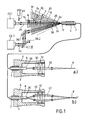
- the irradiation device contains a flexible multimode optical fiber 2 including a fiber sheath 4, and a housing part 6 arranged at the distal end of the light guide in the form of a focusing handpiece with a central cavity 8 receiving the distal end of the light guide, in which a focusing device 10 designed as a lens system is located located.
- the optical fiber 2 is assigned two different coupling angle ranges 14 and 16 within the acceptance cone (acceptance angle ⁇ ) shown in dashed lines in FIG. 1, one of which - 14 - by an inner cone coaxial with the fiber longitudinal axis with half the apex angle ⁇ and the second - 16 - is formed by an outer cone coaxial with the inner cone 14 and enclosing this in an annular manner, the latter being limited by two conical lateral surfaces 18 and 20 which have an opening angle ⁇ 1 or ⁇ 2 which is gradually increased compared to the angle ⁇ .
- the cutting effect of the irradiation device is generated by a light bundle 24 emitted by a laser light source 22.1, which has a mainly ablative, vaporizing effect on biological tissue, that is to say a wavelength of 2.94 ⁇ m, and by a focusing lens 26 within the coupling angle range 14 on the light fiber Face 12 is focused so that it is on the distal fiber face 28, which is also perpendicular to the light fiber longitudinal axis emerges into the cavity 8 with an axial radiation characteristic within a central cone-shaped coupling angle range 30 that corresponds geometrically to the coupling angle range 14 and is focused by the converging lens system 10 in the form of a central cone of light 32 converging in the direction of radiation onto a focus point F lying outside the housing part 6 (FIG. 1a) .
- a second laser light source 22.2 which has a mainly coagulating light beam 34 with a wavelength of z. B. 1.06 microns, which is focused on a mirror system 36 and a focusing lens 38 in the form of a lying within the second coupling angle range 16 light cone on the optical fiber end face 12. Due to the different coupling, this light bundle 34 enters the cavity 8 at the distal light fiber end with circumferential radiation characteristic in a coupling angle region 40 geometrically corresponding to the coupling angle range 16 with respect to the surface normals of the light fiber end faces 12 and 28, i.e. in the form of the ring cone cross-hatched in FIG.
- the cutting 2.94 ⁇ m laser radiation is thus directed onto the center of the operating field while the 1.06 ⁇ m radiation coagulates the surrounding edge area, so that a precise contactless cutting of biological tissue with the central laser radiation 24 or 32 is possible with simultaneous hemostasis by coagulation of the cut surfaces on the edge with the laser beam 34 or 42.
- the coagulation and the ablation effect can be varied together by changing the distance of the housing part 6 from the operating field.
- the laser light sources 22.1 and 22.2 with regard to the operating parameters, e.g. B. the radiation power, the radiation duration or the operating mode can be controlled individually.
- An alternate switchover from one to the other laser light effect can be achieved not only by appropriate control of the two light sources 22, but also by switchable optical elements arranged in the beam path of the laser light bundles 24 and 34, that is to say one that can be moved into the beam path of the light bundle 24 Aperture 44 or the foldable mirror 36.2 of the mirror system 36.
- the radiation device shown in FIG. 2 differs from the first exemplary embodiment essentially only in a different type of coupling-in light generation system and in that the light beams have different focus points.
- the components corresponding to the first exemplary embodiment are therefore identified by the same reference numerals. 2, there is only a single light source 22.3, for example in the form of a neodymium-YAG laser, which is between two different wavelengths, namely a mainly cutting laser radiation of z. B. 1.32 microns and a mainly coagulating acting laser radiation from z. B. 1.06 microns is switchable.
- the laser radiation is deflected depending on the wavelength by a prism 46 connected downstream of the laser 22.3, so that the longer-wave laser light bundle 24 is coupled centrally into the fiber end face 12 in the manner corresponding to FIG. 1 and at the distal end of the housing part 6 in the form of a
- the central cone 32 has a cutting effect, while the short-wave laser radiation which is more strongly deflected on the prism 46 is coupled obliquely into the optical fiber 2 via the mirror 48 within the coupling angle range 16 according to FIG. 1 and at the distal end of the housing part 6 in the form of an outer cone which surrounds the central cone 32 42 is emitted.
- the focal point F 1 of the outer cone 42 is in the radiation direction before the focal point F 2 of the central cone 32.
- the cutting effect of the central light bundle 32 and the coagulating effect of the outer light bundle 42 can be selectively changed in opposite directions to one another.
Landscapes
- Physics & Mathematics (AREA)
- Optics & Photonics (AREA)
- Engineering & Computer Science (AREA)
- Health & Medical Sciences (AREA)
- Plasma & Fusion (AREA)
- Mechanical Engineering (AREA)
- Surgery (AREA)
- Life Sciences & Earth Sciences (AREA)
- Animal Behavior & Ethology (AREA)
- Molecular Biology (AREA)
- Veterinary Medicine (AREA)
- Nuclear Medicine, Radiotherapy & Molecular Imaging (AREA)
- Biomedical Technology (AREA)
- Heart & Thoracic Surgery (AREA)
- Medical Informatics (AREA)
- Otolaryngology (AREA)
- Electromagnetism (AREA)
- General Health & Medical Sciences (AREA)
- Public Health (AREA)
- General Physics & Mathematics (AREA)
- Laser Surgery Devices (AREA)
- Radiation-Therapy Devices (AREA)
Applications Claiming Priority (2)
| Application Number | Priority Date | Filing Date | Title |
|---|---|---|---|
| DE3833992A DE3833992A1 (de) | 1988-10-06 | 1988-10-06 | Bestrahlungseinrichtung |
| DE3833992 | 1988-10-06 |
Publications (2)
| Publication Number | Publication Date |
|---|---|
| EP0366856A2 true EP0366856A2 (fr) | 1990-05-09 |
| EP0366856A3 EP0366856A3 (fr) | 1990-09-26 |
Family
ID=6364502
Family Applications (1)
| Application Number | Title | Priority Date | Filing Date |
|---|---|---|---|
| EP19890106486 Ceased EP0366856A3 (fr) | 1988-10-06 | 1989-04-12 | Dipositif d'irradiation avec des guides d'ondes lumineuses |
Country Status (3)
| Country | Link |
|---|---|
| EP (1) | EP0366856A3 (fr) |
| JP (1) | JPH02102644A (fr) |
| DE (1) | DE3833992A1 (fr) |
Cited By (23)
| Publication number | Priority date | Publication date | Assignee | Title |
|---|---|---|---|---|
| US5409481A (en) * | 1992-05-21 | 1995-04-25 | Laserscope | Laser tissue welding control system |
| EP0893100A3 (fr) * | 1997-07-23 | 1999-09-15 | KALTENBACH & VOIGT GmbH & Co. | Source lumineuse pulsée |
| WO2005003839A1 (fr) * | 2003-06-25 | 2005-01-13 | Institut für Lasertechnologien in der Medizin und Meßtechnik an der Universität Ulm | Procede d'exposition a un rayonnement oriente et/ou de detection de rayonnement avec une resolution directionnelle |
| WO2013086227A1 (fr) * | 2011-12-09 | 2013-06-13 | Jds Uniphase Corporation | Variation du produit des paramètres d'un faisceau laser |
| KR20140098268A (ko) * | 2010-04-08 | 2014-08-07 | 트룸프 레이저-운트 시스템테크닉 게엠베하 | 다중 클래드 섬유에 의해 상이한 비임 프로파일 특징들을 갖는 레이저 비임을 생성하기 위한 방법 및 장치 |
| WO2018217304A1 (fr) * | 2016-09-29 | 2018-11-29 | Nlight, Inc. | Production de répartition d'intensité apparente dans le temps par perturbation rapide de fibre optique à caractéristiques de faisceau variable |
| US10434600B2 (en) | 2015-11-23 | 2019-10-08 | Nlight, Inc. | Fine-scale temporal control for laser material processing |
| WO2019234623A1 (fr) * | 2018-06-05 | 2019-12-12 | Elesta S.R.L. | Dispositif à fibre optique pour ablation thermique au laser et thérapie thermique |
| US10520671B2 (en) | 2015-07-08 | 2019-12-31 | Nlight, Inc. | Fiber with depressed central index for increased beam parameter product |
| US10535973B2 (en) | 2015-01-26 | 2020-01-14 | Nlight, Inc. | High-power, single-mode fiber sources |
| US10656440B2 (en) | 2016-09-29 | 2020-05-19 | Nlight, Inc. | Fiber optical beam delivery device producing output exhibiting intensity distribution profile having non-zero ellipticity |
| US10673198B2 (en) | 2016-09-29 | 2020-06-02 | Nlight, Inc. | Fiber-coupled laser with time varying beam characteristics |
| US10673197B2 (en) | 2016-09-29 | 2020-06-02 | Nlight, Inc. | Fiber-based optical modulator |
| US10673199B2 (en) | 2016-09-29 | 2020-06-02 | Nlight, Inc. | Fiber-based saturable absorber |
| US10677984B2 (en) | 2016-09-29 | 2020-06-09 | Nlight, Inc. | Production of temporally apparent intensity distribution by rapid perturbation of variable beam characteristics optical fiber |
| US10684487B2 (en) | 2016-09-29 | 2020-06-16 | Nlight, Inc. | Frequency-converted optical beams having adjustable beam characteristics |
| US10730785B2 (en) | 2016-09-29 | 2020-08-04 | Nlight, Inc. | Optical fiber bending mechanisms |
| US10732439B2 (en) | 2016-09-29 | 2020-08-04 | Nlight, Inc. | Fiber-coupled device for varying beam characteristics |
| CN111936263A (zh) * | 2018-03-29 | 2020-11-13 | 通快机床两合公司 | 用于产生具有不同功率和亮度的激光辐射的设备和方法 |
| EP3391938B1 (fr) * | 2017-04-17 | 2021-03-17 | Candela Corporation | Dispositif de traitement de la peau |
| US10971884B2 (en) | 2015-03-26 | 2021-04-06 | Nlight, Inc. | Fiber source with cascaded gain stages and/or multimode delivery fiber with low splice loss |
| US10971885B2 (en) | 2014-06-02 | 2021-04-06 | Nlight, Inc. | Scalable high power fiber laser |
| US11179807B2 (en) | 2015-11-23 | 2021-11-23 | Nlight, Inc. | Fine-scale temporal control for laser material processing |
Families Citing this family (4)
| Publication number | Priority date | Publication date | Assignee | Title |
|---|---|---|---|---|
| DE4200587C1 (en) * | 1992-01-11 | 1993-04-01 | Schott Glaswerke, 6500 Mainz, De | Light wave applicator for cutting and coagulating biological tissue - applies laser beam via flexible optical fibre having non-constant refractive index profile along its cross=section |
| DE4209926C2 (de) * | 1992-03-24 | 1996-07-25 | Charite Med Fakultaet | Handstück für medizinische Laseranwendungen |
| DE102007047501A1 (de) * | 2007-10-04 | 2009-04-09 | Rolle + Rolle Gmbh + Co. Kg | Laserfokussierhandstück |
| JP2023058760A (ja) * | 2020-03-26 | 2023-04-26 | パナソニックIpマネジメント株式会社 | 光学装置、レーザ光出力システム、及びレーザ加工機 |
Family Cites Families (6)
| Publication number | Priority date | Publication date | Assignee | Title |
|---|---|---|---|---|
| DE2713904C3 (de) * | 1977-03-29 | 1979-10-04 | Siemens Ag, 1000 Berlin Und 8000 Muenchen | Vorrichtung zum Bearbeiten von Werkstucken mittels eines Laserstrahles |
| US4504111A (en) * | 1981-02-23 | 1985-03-12 | U.S. Philips Corporation | Method of multiplexing transmission chanels in a step-index optical fibre and device for carrying out the method |
| DE3214042A1 (de) * | 1982-04-16 | 1983-10-20 | Licentia Patent-Verwaltungs-Gmbh, 6000 Frankfurt | Faseroptische koppelanordnung |
| DE3415293C2 (de) * | 1984-04-24 | 1987-02-12 | Osada Electric Co. Ltd., Tokio/Tokyo | Laser-Handgerät |
| CA1262757A (fr) * | 1985-04-25 | 1989-11-07 | Richard M. Dwyer | Methode et appareil de chirurgie au laser |
| US5048034A (en) * | 1986-11-20 | 1991-09-10 | Carl Zeiss Stiftung | Long wavelength NdYAG laser |
-
1988
- 1988-10-06 DE DE3833992A patent/DE3833992A1/de active Granted
-
1989
- 1989-04-12 EP EP19890106486 patent/EP0366856A3/fr not_active Ceased
- 1989-08-17 JP JP1210815A patent/JPH02102644A/ja active Pending
Cited By (38)
| Publication number | Priority date | Publication date | Assignee | Title |
|---|---|---|---|---|
| US5409481A (en) * | 1992-05-21 | 1995-04-25 | Laserscope | Laser tissue welding control system |
| EP0893100A3 (fr) * | 1997-07-23 | 1999-09-15 | KALTENBACH & VOIGT GmbH & Co. | Source lumineuse pulsée |
| WO2005003839A1 (fr) * | 2003-06-25 | 2005-01-13 | Institut für Lasertechnologien in der Medizin und Meßtechnik an der Universität Ulm | Procede d'exposition a un rayonnement oriente et/ou de detection de rayonnement avec une resolution directionnelle |
| KR101588544B1 (ko) * | 2010-04-08 | 2016-01-25 | 트룸프 레이저-운트 시스템테크닉 게엠베하 | 다중 클래드 섬유에 의해 상이한 비임 프로파일 특징들을 갖는 레이저 비임을 생성하기 위한 방법 및 장치 |
| KR20140098268A (ko) * | 2010-04-08 | 2014-08-07 | 트룸프 레이저-운트 시스템테크닉 게엠베하 | 다중 클래드 섬유에 의해 상이한 비임 프로파일 특징들을 갖는 레이저 비임을 생성하기 위한 방법 및 장치 |
| KR101456768B1 (ko) * | 2010-04-08 | 2014-10-31 | 트룸프 레이저-운트 시스템테크닉 게엠베하 | 다중 클래드 섬유에 의해 상이한 비임 프로파일 특징들을 갖는 레이저 비임을 생성하기 위한 방법 및 장치 |
| US9823422B2 (en) | 2011-12-09 | 2017-11-21 | Lumentum Operations Llc | Varying beam parameter product of a laser beam |
| US9250390B2 (en) | 2011-12-09 | 2016-02-02 | Lumentum Operations Llc | Varying beam parameter product of a laser beam |
| WO2013086227A1 (fr) * | 2011-12-09 | 2013-06-13 | Jds Uniphase Corporation | Variation du produit des paramètres d'un faisceau laser |
| US10971885B2 (en) | 2014-06-02 | 2021-04-06 | Nlight, Inc. | Scalable high power fiber laser |
| US10535973B2 (en) | 2015-01-26 | 2020-01-14 | Nlight, Inc. | High-power, single-mode fiber sources |
| US10916908B2 (en) | 2015-01-26 | 2021-02-09 | Nlight, Inc. | High-power, single-mode fiber sources |
| US10971884B2 (en) | 2015-03-26 | 2021-04-06 | Nlight, Inc. | Fiber source with cascaded gain stages and/or multimode delivery fiber with low splice loss |
| US10520671B2 (en) | 2015-07-08 | 2019-12-31 | Nlight, Inc. | Fiber with depressed central index for increased beam parameter product |
| US11794282B2 (en) | 2015-11-23 | 2023-10-24 | Nlight, Inc. | Fine-scale temporal control for laser material processing |
| US11331756B2 (en) | 2015-11-23 | 2022-05-17 | Nlight, Inc. | Fine-scale temporal control for laser material processing |
| US11179807B2 (en) | 2015-11-23 | 2021-11-23 | Nlight, Inc. | Fine-scale temporal control for laser material processing |
| US10434600B2 (en) | 2015-11-23 | 2019-10-08 | Nlight, Inc. | Fine-scale temporal control for laser material processing |
| WO2018217304A1 (fr) * | 2016-09-29 | 2018-11-29 | Nlight, Inc. | Production de répartition d'intensité apparente dans le temps par perturbation rapide de fibre optique à caractéristiques de faisceau variable |
| US10732439B2 (en) | 2016-09-29 | 2020-08-04 | Nlight, Inc. | Fiber-coupled device for varying beam characteristics |
| US10663767B2 (en) | 2016-09-29 | 2020-05-26 | Nlight, Inc. | Adjustable beam characteristics |
| US10673198B2 (en) | 2016-09-29 | 2020-06-02 | Nlight, Inc. | Fiber-coupled laser with time varying beam characteristics |
| US10673197B2 (en) | 2016-09-29 | 2020-06-02 | Nlight, Inc. | Fiber-based optical modulator |
| US10673199B2 (en) | 2016-09-29 | 2020-06-02 | Nlight, Inc. | Fiber-based saturable absorber |
| US10677984B2 (en) | 2016-09-29 | 2020-06-09 | Nlight, Inc. | Production of temporally apparent intensity distribution by rapid perturbation of variable beam characteristics optical fiber |
| US10684487B2 (en) | 2016-09-29 | 2020-06-16 | Nlight, Inc. | Frequency-converted optical beams having adjustable beam characteristics |
| US10730785B2 (en) | 2016-09-29 | 2020-08-04 | Nlight, Inc. | Optical fiber bending mechanisms |
| US10656440B2 (en) | 2016-09-29 | 2020-05-19 | Nlight, Inc. | Fiber optical beam delivery device producing output exhibiting intensity distribution profile having non-zero ellipticity |
| WO2018217293A1 (fr) * | 2016-09-29 | 2018-11-29 | Nlight, Inc. | Dispositif de distribution de faisceau optique à fibre produisant une sortie présentant un profil de distribution d'intensité ayant une ellipticité non nulle |
| WO2018217308A1 (fr) * | 2016-09-29 | 2018-11-29 | Nlight, Inc. | Faisceaux optiques convertis en fréquence présentant des caractéristiques de faisceau réglables |
| WO2018217300A1 (fr) * | 2016-09-29 | 2018-11-29 | Nlight, Inc. | Dispositif de couplage de fibre pour moduler les caractéristiques d'un faisceau |
| WO2018217278A1 (fr) * | 2016-09-29 | 2018-11-29 | Nlight, Inc. | Absorbeur saturable à base de fibres |
| US10423015B2 (en) | 2016-09-29 | 2019-09-24 | Nlight, Inc. | Adjustable beam characteristics |
| EP3391938B1 (fr) * | 2017-04-17 | 2021-03-17 | Candela Corporation | Dispositif de traitement de la peau |
| CN111936263A (zh) * | 2018-03-29 | 2020-11-13 | 通快机床两合公司 | 用于产生具有不同功率和亮度的激光辐射的设备和方法 |
| CN112399871A (zh) * | 2018-06-05 | 2021-02-23 | 埃里斯塔股份公司 | 用于激光热烧蚀和热疗的光纤设备 |
| WO2019234623A1 (fr) * | 2018-06-05 | 2019-12-12 | Elesta S.R.L. | Dispositif à fibre optique pour ablation thermique au laser et thérapie thermique |
| US12078852B2 (en) | 2018-06-05 | 2024-09-03 | Elesta S.p.A. | Optical fiber device for laser thermal ablation and thermal therapy |
Also Published As
| Publication number | Publication date |
|---|---|
| EP0366856A3 (fr) | 1990-09-26 |
| DE3833992C2 (fr) | 1992-03-19 |
| DE3833992A1 (de) | 1990-04-12 |
| JPH02102644A (ja) | 1990-04-16 |
Similar Documents
| Publication | Publication Date | Title |
|---|---|---|
| EP0366856A2 (fr) | Dipositif d'irradiation avec des guides d'ondes lumineuses | |
| DE69221806T2 (de) | Vorrichtung zum Abgeben eines defokussierten Laserstrahls mit scharfkantigem Querschnitt | |
| DE10353264B4 (de) | Adapter zum Koppeln einer Laserbearbeitungsvorrichtung mit einem Objekt | |
| DE69105952T3 (de) | Festkörper-Laserdioden-Lichtquelle | |
| DE19836649C2 (de) | Medizinisches Handstück | |
| DE2705202C2 (de) | Chirurgisches Gerät | |
| EP1372518B1 (fr) | Appareil de traitement laser dote d'un systeme d'eclairage | |
| DE3686621T2 (de) | Infrarot laser-kathetergeraet. | |
| DE3934647C2 (de) | Chirurgisches Laserinstrument | |
| EP1309284B1 (fr) | Piece a main destinee au rayonnement de lumiere sur une surface cutanee lors d'un traitement cutane medical ou cosmetique | |
| DE19534590A1 (de) | Scanning Ablation von keramischen Werkstoffen, Kunststoffen und biologischen Hydroxylapatitmaterialien, insbesondere Zahnhartsubstanz | |
| DE2652814A1 (de) | Vorrichtung zur ausrichtung eines arbeitslaserstrahls | |
| DE102006046370A1 (de) | Vorrichtung und Verfahren zur Materialverarbeitung unter Verwendung eines transparenten Kontaktelements | |
| DE4415269A1 (de) | Laseranordnung mit einem axial optisch gepumpten Laser | |
| DE112015002455T5 (de) | Lichtquellenvorrichtung für ein Endoskop | |
| DE102017210350B3 (de) | Vorrichtung zur Auskopplung von Strahlung aus einer Lichtleitfaser, Lichtleitkabel und Bearbeitungskopf damit | |
| DE69231402T2 (de) | Chirurgische lasersonde | |
| EP0523506B1 (fr) | Pièce à main pour application stomatologique de lumière de laser | |
| EP0558164B1 (fr) | Procédé pour couper avec rayonnement du laser | |
| DE3833990C2 (de) | Ballonkatheter | |
| WO1998010317A1 (fr) | Dispositif de transmission de lumiere | |
| DE19517670B4 (de) | Laser-Adapter zur Anordnung an einem Operationsmikroskop sowie geeigneter Laser hierzu | |
| EP0362466A2 (fr) | Dispositf de guides d'ondes lumineuses et d'irradiation | |
| DE69306508T2 (de) | Laser-Generator-Vorrichtung | |
| DD236450B1 (de) | Bestrahlungseinheit fuer medizinische zwecke, insbesondere fuer anwendungen auf dem dentalgebiet |
Legal Events
| Date | Code | Title | Description |
|---|---|---|---|
| PUAI | Public reference made under article 153(3) epc to a published international application that has entered the european phase |
Free format text: ORIGINAL CODE: 0009012 |
|
| AK | Designated contracting states |
Kind code of ref document: A2 Designated state(s): AT BE CH DE ES FR GB GR IT LI LU NL SE |
|
| PUAL | Search report despatched |
Free format text: ORIGINAL CODE: 0009013 |
|
| RHK1 | Main classification (correction) |
Ipc: A61B 17/36 |
|
| AK | Designated contracting states |
Kind code of ref document: A3 Designated state(s): AT BE CH DE ES FR GB GR IT LI LU NL SE |
|
| 17P | Request for examination filed |
Effective date: 19901102 |
|
| RAP1 | Party data changed (applicant data changed or rights of an application transferred) |
Owner name: DEUTSCHE AEROSPACE AKTIENGESELLSCHAFT |
|
| 17Q | First examination report despatched |
Effective date: 19930401 |
|
| STAA | Information on the status of an ep patent application or granted ep patent |
Free format text: STATUS: THE APPLICATION HAS BEEN REFUSED |
|
| 18R | Application refused |
Effective date: 19940327 |