EP0366902A2 - Procédé et dispositif pour le serrage de matière de moulage de fonderie - Google Patents
Procédé et dispositif pour le serrage de matière de moulage de fonderie Download PDFInfo
- Publication number
- EP0366902A2 EP0366902A2 EP89116348A EP89116348A EP0366902A2 EP 0366902 A2 EP0366902 A2 EP 0366902A2 EP 89116348 A EP89116348 A EP 89116348A EP 89116348 A EP89116348 A EP 89116348A EP 0366902 A2 EP0366902 A2 EP 0366902A2
- Authority
- EP
- European Patent Office
- Prior art keywords
- pressure
- valve
- molding
- throttle element
- molding space
- Prior art date
- Legal status (The legal status is an assumption and is not a legal conclusion. Google has not performed a legal analysis and makes no representation as to the accuracy of the status listed.)
- Granted
Links
- 238000000034 method Methods 0.000 title claims abstract description 21
- 239000000463 material Substances 0.000 title description 2
- 238000009434 installation Methods 0.000 title 1
- 239000012778 molding material Substances 0.000 claims abstract description 26
- 230000002040 relaxant effect Effects 0.000 claims abstract 2
- 238000000465 moulding Methods 0.000 claims description 47
- 230000035699 permeability Effects 0.000 claims description 6
- 238000009423 ventilation Methods 0.000 claims description 4
- 230000003111 delayed effect Effects 0.000 claims description 3
- 230000000694 effects Effects 0.000 claims description 2
- 239000007789 gas Substances 0.000 description 14
- 230000006835 compression Effects 0.000 description 11
- 238000007906 compression Methods 0.000 description 11
- 230000008901 benefit Effects 0.000 description 4
- 239000004576 sand Substances 0.000 description 4
- 238000010276 construction Methods 0.000 description 3
- 238000005056 compaction Methods 0.000 description 2
- 230000008569 process Effects 0.000 description 2
- 230000006978 adaptation Effects 0.000 description 1
- 230000000712 assembly Effects 0.000 description 1
- 238000000429 assembly Methods 0.000 description 1
- 230000002238 attenuated effect Effects 0.000 description 1
- 230000008859 change Effects 0.000 description 1
- 239000011248 coating agent Substances 0.000 description 1
- 238000000576 coating method Methods 0.000 description 1
- 230000001934 delay Effects 0.000 description 1
- 238000010586 diagram Methods 0.000 description 1
- 238000005243 fluidization Methods 0.000 description 1
- 238000011835 investigation Methods 0.000 description 1
- 238000004519 manufacturing process Methods 0.000 description 1
- 230000007246 mechanism Effects 0.000 description 1
- 239000012495 reaction gas Substances 0.000 description 1
- 230000009467 reduction Effects 0.000 description 1
- 238000007789 sealing Methods 0.000 description 1
- 238000000926 separation method Methods 0.000 description 1
- 238000007493 shaping process Methods 0.000 description 1
- 239000000126 substance Substances 0.000 description 1
- 238000011144 upstream manufacturing Methods 0.000 description 1
Images

Classifications
-
- B—PERFORMING OPERATIONS; TRANSPORTING
- B22—CASTING; POWDER METALLURGY
- B22C—FOUNDRY MOULDING
- B22C15/00—Moulding machines characterised by the compacting mechanism; Accessories therefor
-
- B—PERFORMING OPERATIONS; TRANSPORTING
- B22—CASTING; POWDER METALLURGY
- B22C—FOUNDRY MOULDING
- B22C9/00—Moulds or cores; Moulding processes
- B22C9/12—Treating moulds or cores, e.g. drying, hardening
- B22C9/123—Gas-hardening
Definitions
- the invention relates to a method and a device for compressing foundry molding material which has been heaped up in a molding space above a model by means of a compressed gas, which suddenly relaxes into the molding space with a relatively lower, then with a high pressure gradient and compresses the molding material as a result of the pressure surge .
- the object of the present invention is to provide a method and a device for the compression of foundry molding material which is distinguished on the one hand by good compression values in critical model areas and on the other by a short cycle time.
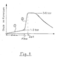
- the first section of the pressure curve expediently runs from atmospheric pressure to an intermediate value of 1 to 3 bar gauge pressure, the subsequent section from this intermediate value to the final pressure, which, as usual, is approximately 4 to 6 bar.
- Different control mechanisms can be used so that a pressure increase with the desired different pressure gradients can be realized within one and the same pressure surge. It is particularly expedient to generate the pressure surge to generate the first, flatter pressure increase in such a way that the relaxation of the pressure surge from the pressure chamber into the molding space is artificially throttled during this period. If the second section should then begin with the higher pressure gradient, this throttling effect only needs to be eliminated.
- This procedure has the advantage that it is possible to work with the valve constructions that have already been tried and tested in practice and that one only has to delay the opening movement of this valve somewhat at the beginning. This then automatically results in an initially flat pressure rise, which then, when the valve opens further and without delay, changes into the steeper pressure increase already practiced.
- a particularly expedient development of the invention consists in generating the pressure surge with its two differently steep sections only over the area of the molding material which is essentially above the model or models, whereas the molding material in the edge area with the usual continuously steep pressure surge, without throttling.
- a device for carrying out the method In the simplest case, one starts from the conventional molding machine with a pressure pulse, in which the valve between the pressure chamber and the molding chamber is actuated by a hydraulic and / or pneumatic pressure medium. In order to bring about the intended delay at the beginning of the opening movement of this valve, an adjustable throttle valve only needs to be installed in a pressure medium line for controlling this valve.
- the flow cross section of the throttle element should be adjustable from about 0% to about 50%, in particular up to about 30% of the free cross section.
- the opening time of the throttle element is adjustable to match the model contour.
- the throttle element can be opened at least partially during the opening movement of the pressure chamber valve.
- the throttle element be formed by perforated plates which are displaceable relative to one another. In one position the perforated plates cover the holes of the neighboring plate, in the other position the perforated plates are aligned.
- the throttle element does not have to extend over the entire cross section of the molding space, but is recommended if it is only in the area above of the model is arranged. In contrast, the rest of the area can remain free. Usually this is the edge area - however, the situation is reversed when shaping bathtubs.
- the throttle element have bulkheads which plunge down into the molding material. These bulkheads extend through the filling frame and, if necessary, also a piece into the molding box.
- Another device for carrying out the method according to the invention is characterized in that two valves are provided between the pressure chamber or the pressure chambers on the one hand and the molding space on the other hand, and that one valve is connected to the inner region of the molding space, which is essentially above the model is located, whereas the other valve is connected to the model-free edge area of the molding space.
- the pressure in the mold space is first increased with an unusually low pressure gradient of 30 to 100 bar / sec until a pressure of approximately 1 to 3 bar is reached.
- This first pressure section 1 then merges seamlessly into a substantially steeper pressure section 2 which has the pressure gradient of approximately 100 to 600 bar / sec that is customary in pulse compression.
- the pressure equalization between the pressure chamber and the molding space is as before at around 3 to 6 bar.
- the pressure reduction then begins, in which the compressed gas escapes through gaps in the molding space and / or through deliberately provided openings, and is optionally suctioned off. The latter comes into consideration if a reaction gas is used as the compressed gas, which brings about a chemical hardening of the molding material.
- the section 1 upstream of the conventional pressure increase 2 causes intensive fluidization of the filled molding material.
- the resulting improved flowability benefits the pressure section 2, which is decisive for the compression, because this pressure section connects directly before the air from the pressure section 1 leaves the molding space.
- the ventilation by the first pressure surge has already largely decayed when the second pressure surge begins.
- the pressure curve according to the invention is therefore particularly suitable for molds with deep bales.
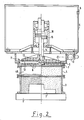
- a pressure vessel 5 - in the exemplary embodiment for receiving compressed air - which is connected via a connection 6 from a pressure accumulator or from the company Compressed air network is fed.
- the pressure vessel has a plate which is provided with a plurality of openings 8 in a rust-like manner in the area above the molding space.
- a frame 9 is flanged to the top of the base 7, to which an exhaust air line with a valve 10 is in turn connected.
- the pressure container 5 with the frame 9 on the one hand and the model plate 1 with model 2, molding box 3 and filling frame 4 on the other hand can be moved relative to one another in order to be able to fill the molding space with molding material to just below the bottom 7. Before the compression, the two assemblies are brought together and pressed tightly at their interface.
- a sealing coating 13 is attached to the underside of the valve plate within the area of the openings 12.
- valve plate 11 is seated on a guide rod 14, which at the same time forms the piston rod of a piston 15 of a pressure medium cylinder 16. This and the control system are described below with reference to FIG. 3.
- the pressure medium cylinder 16 is arranged in a hydraulic circuit, the pressure source of which is designated 17. This is, for example, a hydraulic pump that is fed from a tank 18. From the pressure source 17, the pressure medium reaches the pressure chamber 22 of the pressure medium cylinder 16 via a control slide 19, a check valve 20 and the feed line 21.
- the pressure medium cylinder 16 has a gas pressure chamber 24 which is connected to one Gas pressure accumulator 25 is connected.
- This gas pressure accumulator 25 is divided by a movable piston 26 into a gas pressure chamber 27 and a hydraulic pressure chamber 28.
- the hydraulic pressure chamber 28 is connected via a control slide 29 to a high-pressure source 30, which is fed from the supply tank 18.
- the piston 15 of the pressure medium cylinder 16 is extended on the hydraulic side with a piston rod 31 passing through the pressure chamber 22.
- This upper piston rod 31 carries a cylindrical shoulder 32 and a conically tapered shoulder 33 directly on the shoulder of the piston 15, which forms a throttle with the cylindrical constriction 34 during an upward stroke movement of the piston 15.
- the hydraulic feed line 21 also leads to a controllable check valve 23, the control line of which can be connected to the pressure source 17 via the control slide 19.
- the pressure medium chamber is connected via a branch from the line 21 to an outlet tank 37 and a vent line 38 in a pressure-relieved manner.
- the drain line 39 of the drain tank 37 opens into the hydraulic tank 18.
- the aforementioned branch goes from the feed line 21 to an adjustable throttle 35 and a downstream control slide 36, both of which are connected in parallel to the check valve 23 are and which allow a slow drain of the pressure medium from the pressure chamber 22.
- the check valve 23 After, for example, 50 milliseconds, the check valve 23 also jumps into the open position, so that the outflow from the pressure chamber 22 is released unhindered. The valve 11 then opens abruptly in the previously usual manner up to the maximum opening position and thus generates section 2 of the pressure curve.
- valve 11 The closing of the valve 11 and the other control functions are described in detail in DE-OS 35 18 980, so that reference can be made to avoid repetition.
- a proportional valve is particularly useful. It replaces the check valve 23, the throttle 35 and the control slide 36.
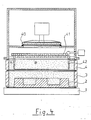
- FIG. 4 shows another implementation possibility for bringing about the pressure curve according to the invention. Only a schematic section of the molding machine is shown, consisting of model plate 1, model 2, molding box 3, filling frame 4 and a mold space opposite valve 40 closing pressure chamber 5.
- the valve 40 is only shown schematically. This can be a construction according to FIG. 2 or any other valve construction. It only has to be ensured that this valve opens quickly enough to bring about a pressure rise rate of 100 to 600 bar / sec in the molding space above the molding material. In contrast, the valve 40 does not need to perform a delayed opening movement as described in FIGS. 2 and 3. The delayed pressure rise at the beginning of the pressure curve is generated here in a different way and is limited to that area of the molding material which is located approximately above the model.
- a throttle element 41 is arranged in the space between the valve 40 and the top of the filled molding material.
- This throttle element consists of two adjacent, horizontally displaceable, rust-like perforated plates, the holes of which are arranged so that they are almost or completely closed in one position of the throttle element, but are open in the other position.
- Such grate plate valves and their actuation are known per se in molding machines, so that there is no need to go into them in detail.
- baffles 42 projecting downwards. These baffles are immersed in the molded material and extend close to or into the molding box. They are positioned so that they are roughly aligned with the outer contour of the models.
- this throttle element is as follows: If the valve 40 is opened, the throttle element 41 is initially almost closed, so that the pressure pulse can only propagate unhindered into the edge region A of the molding space.
- the inner area B which is located below the throttle element 41, however, is only subjected to an attenuated pressure pulse, the pressure gradient of which corresponds to section 1 of the pressure curve in FIG. 1.
- the throttle element 41 goes into its maximum open position and the pressure correspondingly increases with the pressure gradient of section 2 of FIG. 1.
- the design according to FIG. 4 thus allows the pressure curve according to the invention to be used only in that area of the molding material which is essentially above the model, whereas the model-free edge area is subjected to a continuously steep characteristic curve by the conventional pressure pulse.
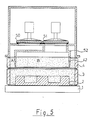
- the design according to FIG. 5 permits an even more individual pressurization of different areas of the molding space.
- the edge area A and inner area B are each connected to their own valves 50 and 51, respectively. Both valves can be opened separately by an individual delay circuit. They are either connected to a common or separate pressure chambers.
- the separation between the areas of the molding space is made by walls 52 which enclose the outlet of the valve 51, then expand above the molding material to the cross section above the model and merge into the vertical guide plates 42.
Landscapes
- Engineering & Computer Science (AREA)
- Mechanical Engineering (AREA)
- Casting Devices For Molds (AREA)
- Mold Materials And Core Materials (AREA)
- Casting Or Compression Moulding Of Plastics Or The Like (AREA)
Applications Claiming Priority (2)
| Application Number | Priority Date | Filing Date | Title |
|---|---|---|---|
| DE3836876 | 1988-10-29 | ||
| DE3836876A DE3836876C2 (de) | 1988-10-29 | 1988-10-29 | Verfahren und Vorrichtung zum Verdichten von Gießerei-Formstoff |
Publications (3)
| Publication Number | Publication Date |
|---|---|
| EP0366902A2 true EP0366902A2 (fr) | 1990-05-09 |
| EP0366902A3 EP0366902A3 (fr) | 1991-11-27 |
| EP0366902B1 EP0366902B1 (fr) | 1994-04-13 |
Family
ID=6366145
Family Applications (1)
| Application Number | Title | Priority Date | Filing Date |
|---|---|---|---|
| EP89116348A Expired - Lifetime EP0366902B1 (fr) | 1988-10-29 | 1989-09-05 | Procédé et dispositif pour le serrage de matière de moulage de fonderie |
Country Status (4)
| Country | Link |
|---|---|
| US (1) | US5020582A (fr) |
| EP (1) | EP0366902B1 (fr) |
| DE (2) | DE3836876C2 (fr) |
| ES (1) | ES2050744T3 (fr) |
Cited By (1)
| Publication number | Priority date | Publication date | Assignee | Title |
|---|---|---|---|---|
| GB2244443B (en) * | 1990-04-20 | 1994-06-01 | Fischer Ag Georg | Method and device for compressing granular moulding materials |
Families Citing this family (6)
| Publication number | Priority date | Publication date | Assignee | Title |
|---|---|---|---|---|
| CH686412A5 (de) * | 1992-03-10 | 1996-03-29 | Fischer Georg Giessereianlagen | Verfahren zum Verdichten von Formsand fuer Giessformen. |
| CZ238594A3 (en) * | 1993-10-27 | 1995-08-16 | Fischer Georg Giessereianlagen | Process of compacting foundry moulding material |
| DE19848048A1 (de) * | 1998-10-19 | 2000-05-04 | Josef Mertes | Verfahren und Vorrichtung zum Verdichten von Formstoffen z. B. Gießerei-Formsand |
| CN104074813B (zh) * | 2014-07-08 | 2016-04-06 | 陈俐丹 | 一种超前预防液压冲击力的控制方法 |
| TW202140587A (zh) * | 2019-12-23 | 2021-11-01 | 日商Dic股份有限公司 | 三維造形用圖案材料、硬化物、立體造形物、鑄模的製造方法及金屬鑄造物的製造方法 |
| CN114713777B (zh) * | 2022-04-15 | 2024-03-15 | 苏州明志科技股份有限公司 | 一种超大型射芯机射芯装置及其控制方法 |
Family Cites Families (15)
| Publication number | Priority date | Publication date | Assignee | Title |
|---|---|---|---|---|
| US3916976A (en) * | 1971-04-05 | 1975-11-04 | Sherwin Williams Co | Process for producing foundry sand molds |
| DE2361820C3 (de) * | 1973-01-29 | 1975-07-03 | Eugen Dipl.-Ing. 8871 Burtenbach Buehler | Verfahren und Vorrichtung zum Weitertransportieren eines aus horizontal geteilten kastenlosen Gießformen gebildeten Formstranges längs einer GIeB- und Kühlstrecke |
| JPS55147462A (en) * | 1979-05-08 | 1980-11-17 | Sintokogio Ltd | Molding method of lower mold and squeeze plate device |
| DE2844464C2 (de) * | 1978-10-12 | 1983-03-24 | Bühler, Eugen, Dipl.-Ing., 8871 Burtenbach | Verfahren und Vorrichtung zum Verdichten von Gießformen |
| DE3149172A1 (de) * | 1981-12-11 | 1983-06-30 | Georg Fischer AG, 8201 Schaffhausen | "verfahren zur herstellung von formkoerpern mittels gasdruck" |
| EP0170765B1 (fr) * | 1981-12-28 | 1988-08-31 | BMD Badische Maschinenfabrik Durlach GmbH | Dispositif pour comprimer du matériel de moulage pour fonderies |
| DE3319496A1 (de) * | 1982-06-29 | 1983-12-29 | VEB Kombinat Gießereianlagenbau und Gußerzeugnisse - GISAG -, DDR 7031 Leipzig | Vorrichtung zum verdichten von giessereiformstoffen mittels druckimpulsen |
| CH659012A5 (de) * | 1982-07-20 | 1986-12-31 | Fischer Ag Georg | Verfahren und vorrichtung zum verdichten von koernigen formstoffen. |
| DE3317196A1 (de) * | 1983-05-11 | 1984-11-22 | BMD Badische Maschinenfabrik Durlach GmbH, 7500 Karlsruhe | Vorrichtung zum verdichten von giessereiformsand |
| DE3344520A1 (de) * | 1983-12-09 | 1985-06-20 | BMD Badische Maschinenfabrik Durlach GmbH, 7500 Karlsruhe | Vorrichtung zum verdichten von giesserei-formstoff mittels druckgas |
| US4598756A (en) * | 1984-09-04 | 1986-07-08 | Kabushiki Kaisha Komatsu Seisakusho | Method for making sand molds |
| DE3511283A1 (de) * | 1985-03-28 | 1986-10-09 | Dietmar Prof. Dr.-Ing. 5100 Aachen Boenisch | Verfahren und vorrichtung zum verdichten von giessereiformstoffen |
| DE3518980A1 (de) * | 1985-05-25 | 1986-11-27 | BMD Badische Maschinenfabrik Durlach GmbH, 7500 Karlsruhe | Vorrichtung zum verdichten von giesserei-formstoff mittels druckgas |
| CH672270A5 (fr) * | 1986-12-17 | 1989-11-15 | Fischer Ag Georg | |
| DD260454A1 (de) * | 1987-05-13 | 1988-09-28 | Kunert Giesserei Maschbau Veb | Verfahren und formmaschine zur herstellung von giessformen mittels gasdruckimpulsen |
-
1988
- 1988-10-29 DE DE3836876A patent/DE3836876C2/de not_active Expired - Lifetime
-
1989
- 1989-09-05 EP EP89116348A patent/EP0366902B1/fr not_active Expired - Lifetime
- 1989-09-05 ES ES89116348T patent/ES2050744T3/es not_active Expired - Lifetime
- 1989-09-05 DE DE58907453T patent/DE58907453D1/de not_active Expired - Fee Related
- 1989-10-24 US US07/426,588 patent/US5020582A/en not_active Expired - Fee Related
Cited By (1)
| Publication number | Priority date | Publication date | Assignee | Title |
|---|---|---|---|---|
| GB2244443B (en) * | 1990-04-20 | 1994-06-01 | Fischer Ag Georg | Method and device for compressing granular moulding materials |
Also Published As
| Publication number | Publication date |
|---|---|
| DE3836876A1 (de) | 1989-04-27 |
| US5020582A (en) | 1991-06-04 |
| ES2050744T3 (es) | 1994-06-01 |
| DE58907453D1 (de) | 1994-05-19 |
| EP0366902A3 (fr) | 1991-11-27 |
| DE3836876C2 (de) | 1994-06-09 |
| EP0366902B1 (fr) | 1994-04-13 |
Similar Documents
| Publication | Publication Date | Title |
|---|---|---|
| EP0295472A2 (fr) | Procédé et dispositif pour le serrage de matière de moulage dans une machine à mouler pour fonderie | |
| EP0366902B1 (fr) | Procédé et dispositif pour le serrage de matière de moulage de fonderie | |
| DE4425334C2 (de) | Verfahren und Vorrichtung zur Herstellung von Formen oder Formteilen durch Verdichtung von partikelförmigem Material | |
| EP0170765B1 (fr) | Dispositif pour comprimer du matériel de moulage pour fonderies | |
| DE69509866T2 (de) | Formmaschine | |
| DE2933869C2 (de) | Verfahren und Vorrichtung zum Herstellen eines unteren Formteils | |
| DE69103826T2 (de) | Verfahren und Vorrichtung zur Durchführung flüssigen Metalls in eine Sandgiessform mittels Niederdruck. | |
| EP0089547B1 (fr) | Procédé et dispositif pour compacter du sable de moulage de fonderie | |
| EP0131723B1 (fr) | Dispositif pour le serrage de matière de moulage de fonderie à l'aide de gaz comprimé | |
| DE3442021C2 (fr) | ||
| DE3518980C2 (fr) | ||
| DE69604358T2 (de) | Verfahren und Vorrichtung zur Herstellung gasaushärtbarer Formen | |
| DE2704322A1 (de) | Niederdruck-druckgussmaschine | |
| DE3344520C2 (fr) | ||
| DE69108306T2 (de) | Verfahren, Giessform und Vorrichtung zum mehrstufigen Niederdruckgiessen von Metall. | |
| DE3914160C1 (fr) | ||
| DE2701693C2 (de) | Formmaschine zum Herstellen von Gießformen | |
| DE69209567T2 (de) | Verfahren zum Fördern von pulverförmigem Material in Pressformen für Keramik | |
| DE3234545C2 (de) | Vorrichtung zum Herstellen von SMC-Teilen | |
| DE3317196A1 (de) | Vorrichtung zum verdichten von giessereiformsand | |
| DE3019455A1 (de) | Schiesskopf fuer sandformmaschine | |
| DE10127948C1 (de) | Verfahren zum Innenhochdruck-Umformen und schließbares Werkzeug zum Durchführen des Verfahrens | |
| CH668014A5 (de) | Verfahren zum einfuellen der dosiermenge in eine druckgiessmaschine sowie druckgiessmaschine zur durchfuehrung des verfahrens. | |
| DE60112625T2 (de) | Adaptive steuerung von formwerkzeugkomprimierbarkeit | |
| AT355745B (de) | Formmaschine zur herstellung von giessformen in formkaesten |
Legal Events
| Date | Code | Title | Description |
|---|---|---|---|
| PUAI | Public reference made under article 153(3) epc to a published international application that has entered the european phase |
Free format text: ORIGINAL CODE: 0009012 |
|
| AK | Designated contracting states |
Kind code of ref document: A2 Designated state(s): CH DE ES FR GB IT LI SE |
|
| PUAL | Search report despatched |
Free format text: ORIGINAL CODE: 0009013 |
|
| AK | Designated contracting states |
Kind code of ref document: A3 Designated state(s): CH DE ES FR GB IT LI SE |
|
| 17P | Request for examination filed |
Effective date: 19920117 |
|
| 17Q | First examination report despatched |
Effective date: 19930215 |
|
| GRAA | (expected) grant |
Free format text: ORIGINAL CODE: 0009210 |
|
| AK | Designated contracting states |
Kind code of ref document: B1 Designated state(s): CH DE ES FR GB IT LI SE |
|
| PG25 | Lapsed in a contracting state [announced via postgrant information from national office to epo] |
Ref country code: SE Free format text: THE PATENT HAS BEEN ANNULLED BY A DECISION OF A NATIONAL AUTHORITY Effective date: 19940413 |
|
| ITF | It: translation for a ep patent filed | ||
| REF | Corresponds to: |
Ref document number: 58907453 Country of ref document: DE Date of ref document: 19940519 |
|
| REG | Reference to a national code |
Ref country code: ES Ref legal event code: FG2A Ref document number: 2050744 Country of ref document: ES Kind code of ref document: T3 |
|
| GBT | Gb: translation of ep patent filed (gb section 77(6)(a)/1977) |
Effective date: 19940630 |
|
| ET | Fr: translation filed | ||
| PLBE | No opposition filed within time limit |
Free format text: ORIGINAL CODE: 0009261 |
|
| STAA | Information on the status of an ep patent application or granted ep patent |
Free format text: STATUS: NO OPPOSITION FILED WITHIN TIME LIMIT |
|
| 26N | No opposition filed | ||
| PGFP | Annual fee paid to national office [announced via postgrant information from national office to epo] |
Ref country code: GB Payment date: 20010815 Year of fee payment: 13 |
|
| PGFP | Annual fee paid to national office [announced via postgrant information from national office to epo] |
Ref country code: CH Payment date: 20010821 Year of fee payment: 13 |
|
| PGFP | Annual fee paid to national office [announced via postgrant information from national office to epo] |
Ref country code: ES Payment date: 20010920 Year of fee payment: 13 |
|
| PGFP | Annual fee paid to national office [announced via postgrant information from national office to epo] |
Ref country code: FR Payment date: 20010926 Year of fee payment: 13 Ref country code: DE Payment date: 20010926 Year of fee payment: 13 |
|
| REG | Reference to a national code |
Ref country code: GB Ref legal event code: IF02 |
|
| PG25 | Lapsed in a contracting state [announced via postgrant information from national office to epo] |
Ref country code: GB Free format text: LAPSE BECAUSE OF NON-PAYMENT OF DUE FEES Effective date: 20020905 |
|
| PG25 | Lapsed in a contracting state [announced via postgrant information from national office to epo] |
Ref country code: ES Free format text: LAPSE BECAUSE OF NON-PAYMENT OF DUE FEES Effective date: 20020906 |
|
| PG25 | Lapsed in a contracting state [announced via postgrant information from national office to epo] |
Ref country code: LI Free format text: LAPSE BECAUSE OF NON-PAYMENT OF DUE FEES Effective date: 20020930 Ref country code: CH Free format text: LAPSE BECAUSE OF NON-PAYMENT OF DUE FEES Effective date: 20020930 |
|
| PG25 | Lapsed in a contracting state [announced via postgrant information from national office to epo] |
Ref country code: DE Free format text: LAPSE BECAUSE OF NON-PAYMENT OF DUE FEES Effective date: 20030401 |
|
| GBPC | Gb: european patent ceased through non-payment of renewal fee |
Effective date: 20020905 |
|
| REG | Reference to a national code |
Ref country code: CH Ref legal event code: PL |
|
| PG25 | Lapsed in a contracting state [announced via postgrant information from national office to epo] |
Ref country code: FR Free format text: LAPSE BECAUSE OF NON-PAYMENT OF DUE FEES Effective date: 20030603 |
|
| REG | Reference to a national code |
Ref country code: FR Ref legal event code: ST |
|
| REG | Reference to a national code |
Ref country code: ES Ref legal event code: FD2A Effective date: 20031011 |
|
| PG25 | Lapsed in a contracting state [announced via postgrant information from national office to epo] |
Ref country code: IT Free format text: LAPSE BECAUSE OF NON-PAYMENT OF DUE FEES;WARNING: LAPSES OF ITALIAN PATENTS WITH EFFECTIVE DATE BEFORE 2007 MAY HAVE OCCURRED AT ANY TIME BEFORE 2007. THE CORRECT EFFECTIVE DATE MAY BE DIFFERENT FROM THE ONE RECORDED. Effective date: 20050905 |